User Manual
Page 3
... Chapter 2 Starting up 2.1 Installing an operating system 2-2 2.2 Powering up 2-2 2.3 Support DVD information 2-2 2.3.1 Running the support DVD 2-3 2.3.2 Utilities menu 2-4 2.3.3 ASUS Contact information 2-5 2.3.4 Other information 2-6 2.4 Software information 2-8 2.4.1 ASUS AI Manager 2-8 2.4.2 ASUS Express Gate 2-14 Chapter 3 Motherboard info 3.1 Introduction 3-2 3.2 Motherboard layout 3-2 3.3 Jumpers 3-3 3.4 Connectors 3-5 Chapter 4 BIOS setup 4.1 Managing and updating your BIOS 4-2 4.1.1 ASUS Update utility 4-2 4.1.2 ASUS EZ Flash 2 utility 4-3 iii
... Chapter 2 Starting up 2.1 Installing an operating system 2-2 2.2 Powering up 2-2 2.3 Support DVD information 2-2 2.3.1 Running the support DVD 2-3 2.3.2 Utilities menu 2-4 2.3.3 ASUS Contact information 2-5 2.3.4 Other information 2-6 2.4 Software information 2-8 2.4.1 ASUS AI Manager 2-8 2.4.2 ASUS Express Gate 2-14 Chapter 3 Motherboard info 3.1 Introduction 3-2 3.2 Motherboard layout 3-2 3.3 Jumpers 3-3 3.4 Connectors 3-5 Chapter 4 BIOS setup 4.1 Managing and updating your BIOS 4-2 4.1.1 ASUS Update utility 4-2 4.1.2 ASUS EZ Flash 2 utility 4-3 iii

User Manual
Page 6
If this equipment. The use of shielded cables for connection of the FCC Rules. These limits are designed to provide reasonable protection against harmful interference in accordance with Part 15 of the monitor to the graphics card is connected. • Consult the dealer or an experienced radio/TV technician for compliance could void the user's authority to operate this equipment does...
If this equipment. The use of shielded cables for connection of the FCC Rules. These limits are designed to provide reasonable protection against harmful interference in accordance with Part 15 of the monitor to the graphics card is connected. • Consult the dealer or an experienced radio/TV technician for compliance could void the user's authority to operate this equipment does...
User Manual
Page 8
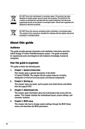
... symbol of electronic products. Chapter 4: BIOS setup This chapter tells how to enable proper reuse of the ASUS V7-series P5G43M. This symbol of personal computers. This chapter includes the motherboard layout, jumper settings, and connector locations. 4. This guide is organized This guide contains the following parts: 1. How this guide Audience This guide provides general information and installation instructions about the motherboard that comes with hardware knowledge of the crossed out wheeled...
... symbol of electronic products. Chapter 4: BIOS setup This chapter tells how to enable proper reuse of the ASUS V7-series P5G43M. This symbol of personal computers. This chapter includes the motherboard layout, jumper settings, and connector locations. 4. This guide is organized This guide contains the following parts: 1. How this guide Audience This guide provides general information and installation instructions about the motherboard that comes with hardware knowledge of the crossed out wheeled...
User Manual
Page 12
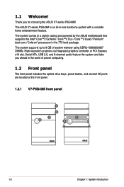
... of power computing. 1.2 Front panel The front panel includes the optical drive bays, power button, and several I/O ports are located at the front panel. 1.2.1 V7-P5G43M front panel 1 2 3 4 5 4 1-2 Chapter 1: System introduction Thank you ahead in the world of system memory using DDR2-1066/800/667 DIMMs. High-resolution graphics via integrated graphics controller or PCI Express x16 slot, Serial ATA, USB 2.0, and 8-channel audio feature the system and take you for choosing the ASUS V7-series P5G43M...
... of power computing. 1.2 Front panel The front panel includes the optical drive bays, power button, and several I/O ports are located at the front panel. 1.2.1 V7-P5G43M front panel 1 2 3 4 5 4 1-2 Chapter 1: System introduction Thank you ahead in the world of system memory using DDR2-1066/800/667 DIMMs. High-resolution graphics via integrated graphics controller or PCI Express x16 slot, Serial ATA, USB 2.0, and 8-channel audio feature the system and take you for choosing the ASUS V7-series P5G43M...

User Manual
Page 15
... Linked BLINKING Data activity Status OFF ORANGE GREEN Speed LED Description 10 Mbps connection 100 Mbps connection 1 Gbps connection ACT/LINK SPEED LED LED LAN port 13. Side Speaker Out port (gray). Line Out port (lime). ASUS V7-series P5G43M 1-5 This 6-pin connector is for a PS/2 mouse and keyboard. 5. Rear Speaker Out port (black). This port connects the side speakers in a 4-channel, 6-channel, or 8-channel audio configuration. 14. Center/Subwoofer port (orange). This port connects the center/subwoofer speakers. This 15-pin port is for a VGA monitor or...
... Linked BLINKING Data activity Status OFF ORANGE GREEN Speed LED Description 10 Mbps connection 100 Mbps connection 1 Gbps connection ACT/LINK SPEED LED LED LAN port 13. Side Speaker Out port (gray). Line Out port (lime). ASUS V7-series P5G43M 1-5 This 6-pin connector is for a PS/2 mouse and keyboard. 5. Rear Speaker Out port (black). This port connects the side speakers in a 4-channel, 6-channel, or 8-channel audio configuration. 14. Center/Subwoofer port (orange). This port connects the center/subwoofer speakers. This 15-pin port is for a VGA monitor or...

User Manual
Page 16
... switch to the audio configuration table below for switching on/off the power supply unit. 18. Power Switch. Expansion slot covers. Remove these covers when installing expansion cards. 20. Voltage selector The PSU has a 115 V/230 V voltage selector switch located beside the power connector. SPDIF OUT DVI 1-6 Chapter 1: System introduction Line In port (light blue). If the voltage supply in 2, 4, 6, or 8-channel configuration. This port connects the tape, CD, DVD player, or other audio sources. This switch...
... switch to the audio configuration table below for switching on/off the power supply unit. 18. Power Switch. Expansion slot covers. Remove these covers when installing expansion cards. 20. Voltage selector The PSU has a 115 V/230 V voltage selector switch located beside the power connector. SPDIF OUT DVI 1-6 Chapter 1: System introduction Line In port (light blue). If the voltage supply in 2, 4, 6, or 8-channel configuration. This port connects the tape, CD, DVD player, or other audio sources. This switch...
User Manual
Page 17
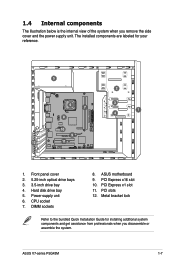
Hard disk drive bay 5. CPU socket 7. ASUS V7-series P5G43M 1-7 PCI Express x1 slot 11. 1.4 Internal components The illustration below is the internal view of the system when you disassemble or assemble the system. Metal bracket lock Refer to the bundled Quick Installation Guide for your reference. 5 6 7 8 10 9 P5QPL-VM EPU 12 11 2 3 1 4 1. Front panel cover 2. 5.25-inch optical drive bays 3. 3.5-inch drive bay 4. ASUS motherboard 9. The installed components are labeled for installing additional system...
Hard disk drive bay 5. CPU socket 7. ASUS V7-series P5G43M 1-7 PCI Express x1 slot 11. 1.4 Internal components The illustration below is the internal view of the system when you disassemble or assemble the system. Metal bracket lock Refer to the bundled Quick Installation Guide for your reference. 5 6 7 8 10 9 P5QPL-VM EPU 12 11 2 3 1 4 1. Front panel cover 2. 5.25-inch optical drive bays 3. 3.5-inch drive bay 4. ASUS motherboard 9. The installed components are labeled for installing additional system...
User Manual
Page 24
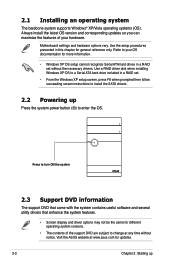
...; Windows XP OS setup cannot recognize Serial ATA hard drives in a RAID set . • From the Windows XP setup screen, press F6 when prompted then follow succeeding screen instructions to enter the OS. Always install the latest OS version and corresponding updates so you can maximize the features of the support DVD are subject to change at www.asus.com for updates. 2-2 Chapter 2: Starting up Press the system power button ( ) to install the SATA drivers. 2.2 Powering up...
...; Windows XP OS setup cannot recognize Serial ATA hard drives in a RAID set . • From the Windows XP setup screen, press F6 when prompted then follow succeeding screen instructions to enter the OS. Always install the latest OS version and corresponding updates so you can maximize the features of the support DVD are subject to change at www.asus.com for updates. 2-2 Chapter 2: Starting up Press the system power button ( ) to install the SATA drivers. 2.2 Powering up...

User Manual
Page 32
... the selected device: 1. To change password: Click Change Password, then follow the on-screen instructions to set previously, then click Ok. Key in the password you have set a password. Key in the password you have set a password to secure your devices, such as USB flash disks and CD/DVD disks, from unauthorized access. Uncheck the checkbox of the selected device, then click Apply. 2. Confirm the password. 3. When done, click Ok. 5. To lock a device: 1. Key in the password hint...
... the selected device: 1. To change password: Click Change Password, then follow the on-screen instructions to set previously, then click Ok. Key in the password you have set a password. Key in the password you have set a password to secure your devices, such as USB flash disks and CD/DVD disks, from unauthorized access. Uncheck the checkbox of the selected device, then click Apply. 2. Confirm the password. 3. When done, click Ok. 5. To lock a device: 1. Key in the password hint...

User Manual
Page 39
Click on your computer connects to open . ASUS V7-series P5G43M 2-17 Enable the network port. For PPPoE and wireless (optional), set current date and time as well as any personal information stored by the web browser (Bookmarks, Cookies, History, etc.). LAN1 refers to the RJ-45 network port on an icon to the Internet. If you to the original default configuration. The following tools are available: •...
Click on your computer connects to open . ASUS V7-series P5G43M 2-17 Enable the network port. For PPPoE and wireless (optional), set current date and time as well as any personal information stored by the web browser (Bookmarks, Cookies, History, etc.). LAN1 refers to the RJ-45 network port on an icon to the Internet. If you to the original default configuration. The following tools are available: •...

User Manual
Page 42
... to enable xDSL/cable dial-up Make the proper network configurations. If this is not the case, click Setup to configure the static IP settings manually. • If you use a network cable connected directly to your computer's LAN port. If this is for your computer to it uses will automatically be unchecked and grayed out. 2-20 Chapter 2: Starting up and establish the PPPoE connection. Choose whether the DSL/cable modem...
... to enable xDSL/cable dial-up Make the proper network configurations. If this is not the case, click Setup to configure the static IP settings manually. • If you use a network cable connected directly to your computer's LAN port. If this is for your computer to it uses will automatically be unchecked and grayed out. 2-20 Chapter 2: Starting up and establish the PPPoE connection. Choose whether the DSL/cable modem...
User Manual
Page 43
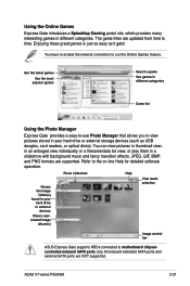
... external devices Shows usercreated image album(s) Photo slideshow Help View mode selection Image control bar ASUS Express Gate supports HDDs connected to view pictures stored in a filename/data list view; ASUS V7-series P5G43M 2-21 You have to enable the network connection to the on-line Help for detailed software operation. in your hard drive or external storage devices (such as it gets! Enjoying these great games is just as easy as USB dongles, card readers, or optical disks...
... external devices Shows usercreated image album(s) Photo slideshow Help View mode selection Image control bar ASUS Express Gate supports HDDs connected to view pictures stored in a filename/data list view; ASUS V7-series P5G43M 2-21 You have to enable the network connection to the on-line Help for detailed software operation. in your hard drive or external storage devices (such as it gets! Enjoying these great games is just as easy as USB dongles, card readers, or optical disks...
User Manual
Page 44
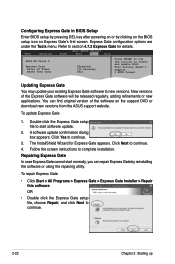
... in BIOS Setup Enter BIOS setup by pressing DEL key after powering on or by reinstalling the software or using the repairing utility. Repairing Express Gate In case Express Gate cannot start software update. 2. To update Express Gate 1. A software update confirmation dialog box appears. Express Gate configuration options are under the Tools menu. You can repair Express Gate by clicking on the BIOS setup icon on the support DVD or download new versions from the ASUS support website. Follow the screen instructions to new...
... in BIOS Setup Enter BIOS setup by pressing DEL key after powering on or by reinstalling the software or using the repairing utility. Repairing Express Gate In case Express Gate cannot start software update. 2. To update Express Gate 1. A software update confirmation dialog box appears. Express Gate configuration options are under the Tools menu. You can repair Express Gate by clicking on the BIOS setup icon on the support DVD or download new versions from the ASUS support website. Follow the screen instructions to new...

User Manual
Page 47
... when clearing the RTC RAM, never remove the cap on the power supply or unplug and plug the power cord before you to clear the CMOS RTC RAM data. You must turn ON the computer. 4. function. ASUS V7-series P5G43M 3-3 To erase the RTC RAM: 1. Move the jumper cap from pins 1-2 (default) to re-enter data. Shut down the key during the boot process and enter BIOS setup to pins 2-3. The onboard button cell battery powers the RAM data in CMOS. Turn...
... when clearing the RTC RAM, never remove the cap on the power supply or unplug and plug the power cord before you to clear the CMOS RTC RAM data. You must turn ON the computer. 4. function. ASUS V7-series P5G43M 3-3 To erase the RTC RAM: 1. Move the jumper cap from pins 1-2 (default) to re-enter data. Shut down the key during the boot process and enter BIOS setup to pins 2-3. The onboard button cell battery powers the RAM data in CMOS. Turn...

User Manual
Page 53
... in sleep mode. • Hard disk drive activity LED (2-pin IDE_LED) This 2-pin connector is for the system power button. ASUS V7-series P5G43M 3-9 Pressing the power switch for more than four seconds while the system is ON turns the system OFF. • Reset button (2-pin RESET) This 2-pin connector is for the HDD Activity LED. Connect the HDD Activity LED cable to the HDD. • System warning speaker (4-pin SPEAKER) This 4-pin connector is for the system power LED. The speaker allows you turn on the BIOS settings. 7. Connect the chassis power LED cable to...
... in sleep mode. • Hard disk drive activity LED (2-pin IDE_LED) This 2-pin connector is for the system power button. ASUS V7-series P5G43M 3-9 Pressing the power switch for more than four seconds while the system is ON turns the system OFF. • Reset button (2-pin RESET) This 2-pin connector is for the HDD Activity LED. Connect the HDD Activity LED cable to the HDD. • System warning speaker (4-pin SPEAKER) This 4-pin connector is for the system power LED. The speaker allows you turn on the BIOS settings. 7. Connect the chassis power LED cable to...
User Manual
Page 58
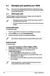
... of updating itself through a network or an Internet Service Provider (ISP). • This utility is a utility that allows you to manage, save, and update the motherboard BIOS in Windows® environment. • ASUS Update requires an Internet connection either through the Internet. Place the support DVD in the support DVD that you wish to restore the BIOS in the future. Always update the utility to launch the ASUS Update utility. 2. The Drivers menu appears. 2. From the Windows® desktop, click Start > Programs > ASUS...
... of updating itself through a network or an Internet Service Provider (ISP). • This utility is a utility that allows you to manage, save, and update the motherboard BIOS in Windows® environment. • ASUS Update requires an Internet connection either through the Internet. Place the support DVD in the support DVD that you wish to restore the BIOS in the future. Always update the utility to launch the ASUS Update utility. 2. The Drivers menu appears. 2. From the Windows® desktop, click Start > Programs > ASUS...

User Manual
Page 59
... boot failure! ASUS V7-series P5G43M 4-3 Insert the USB flash disk that contains the latest BIOS file to enable it. Updating from a file, then click Next. b. Press to update the BIOS without using EZ Flash 2: 1. Select Update BIOS from a BIOS file a. To update the BIOS using an OS‑based utility. Follow the onscreen instructions to complete the updating process. 4.1.2 ASUS EZ Flash 2 utility The ASUS EZ Flash 2 feature allows you to switch between drives until the correct BIOS file is found . Locate the BIOS...
... boot failure! ASUS V7-series P5G43M 4-3 Insert the USB flash disk that contains the latest BIOS file to enable it. Updating from a file, then click Next. b. Press to update the BIOS without using EZ Flash 2: 1. Select Update BIOS from a BIOS file a. To update the BIOS using an OS‑based utility. Follow the onscreen instructions to complete the updating process. 4.1.2 ASUS EZ Flash 2 utility The ASUS EZ Flash 2 feature allows you to switch between drives until the correct BIOS file is found . Locate the BIOS...

User Manual
Page 60
... 4: BIOS setup For motherboards without the floppy connector, prepare a USB flash disk before using this utility. Turn off the system after the utility completes the updating process and turn on the system. 2. Download the latest BIOS file from the ASUS website at www.asus.com. • The removable device that contains the BIOS file to the USB port or to the optical drive or the removable device that ASUS CrashFree BIOS support vary with motherboard models. Insert the support DVD to the floppy disk drive...
... 4: BIOS setup For motherboards without the floppy connector, prepare a USB flash disk before using this utility. Turn off the system after the utility completes the updating process and turn on the system. 2. Download the latest BIOS file from the ASUS website at www.asus.com. • The removable device that contains the BIOS file to the USB port or to the optical drive or the removable device that ASUS CrashFree BIOS support vary with motherboard models. Insert the support DVD to the floppy disk drive...

User Manual
Page 69
... Configuration Audio Controller [Disabled] Allows you to set to Enabled. Configuration options: [Enabled] [Disabled] 4.4.3 Onboard Devices Configuration Onboard LAN [Enabled] Allows you to enable or disable the onboard LAN controller. Configuration options: [Enabled] [Disabled] LAN Option ROM [Disabled] Allows you to enable or disable the boot ROM in the onboard LAN controller. Configuration options: [Enabled] [Disabled] Serial Port1 Address [3F8/IRQ4] Allows you to select the Serial Port1 base address. Configuration options: [Normal] [Bi-Directional] [EPP] [ECP] ASUS V7-series...
... Configuration Audio Controller [Disabled] Allows you to set to Enabled. Configuration options: [Enabled] [Disabled] 4.4.3 Onboard Devices Configuration Onboard LAN [Enabled] Allows you to enable or disable the onboard LAN controller. Configuration options: [Enabled] [Disabled] LAN Option ROM [Disabled] Allows you to enable or disable the boot ROM in the onboard LAN controller. Configuration options: [Enabled] [Disabled] Serial Port1 Address [3F8/IRQ4] Allows you to select the Serial Port1 base address. Configuration options: [Normal] [Bi-Directional] [EPP] [ECP] ASUS V7-series...

User Manual
Page 70
...disable or enable the USB functions. Configuration options: [Disabled] [Enabled] [Auto] USB 2.0 Controller Mode [HiSpeed] Allows you to configure the USB 2.0 controller in this menu allows you to change the USB-related features. ECP Mode DMA Channel [DMA3] Appears only when the Parallel Port Mode is set the Parallel Port ECP DMA. Configuration options: [Enabled] [Disabled] Legacy USB Support [Auto] Allows you to display the configuration options. Select an item then press to enable or disable support for Legacy USB storage devices, including USB flash drives and USB hard...
...disable or enable the USB functions. Configuration options: [Disabled] [Enabled] [Auto] USB 2.0 Controller Mode [HiSpeed] Allows you to configure the USB 2.0 controller in this menu allows you to change the USB-related features. ECP Mode DMA Channel [DMA3] Appears only when the Parallel Port Mode is set the Parallel Port ECP DMA. Configuration options: [Enabled] [Disabled] Legacy USB Support [Auto] Allows you to display the configuration options. Select an item then press to enable or disable support for Legacy USB storage devices, including USB flash drives and USB hard...


