TUWE-M User Manual
Page 1
® TUWE-M Intel® 810E2 MicroATX Motherboard USER'S MANUAL
® TUWE-M Intel® 810E2 MicroATX Motherboard USER'S MANUAL
TUWE-M User Manual
Page 4
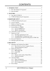
CONTENTS 1. HARDWARE SETUP 14 3.1 TUWE-M Motherboard Layout 14 3.2 Layout Contents 15 3.3 Hardware Setup Procedure 16 3.4 Motherboard Settings 16 3.5 System Memory (DIMM 21 3.5.1 General DIMM Notes 21 3.5.2 Memory Installation 22 3.6 Central Processing Unit... 52 4.4 Advanced Menu 54 4.4.1 Chip Configuration 56 4.4.2 I/O Device Configuration 58 4.4.3 PCI Configuration 60 4.5 Power Menu 62 4 ASUS TUWE-M User's Manual INTRODUCTION 7 1.1 How This Manual Is Organized 7 1.2 Item Checklist 7 2. FEATURES 8 2.1 The ASUS TUWE-M 8 2.2 TUWE-M Motherboard Components 12 3.
CONTENTS 1. HARDWARE SETUP 14 3.1 TUWE-M Motherboard Layout 14 3.2 Layout Contents 15 3.3 Hardware Setup Procedure 16 3.4 Motherboard Settings 16 3.5 System Memory (DIMM 21 3.5.1 General DIMM Notes 21 3.5.2 Memory Installation 22 3.6 Central Processing Unit... 52 4.4 Advanced Menu 54 4.4.1 Chip Configuration 56 4.4.2 I/O Device Configuration 58 4.4.3 PCI Configuration 60 4.5 Power Menu 62 4 ASUS TUWE-M User's Manual INTRODUCTION 7 1.1 How This Manual Is Organized 7 1.2 Item Checklist 7 2. FEATURES 8 2.1 The ASUS TUWE-M 8 2.2 TUWE-M Motherboard Components 12 3.
TUWE-M User Manual
Page 5
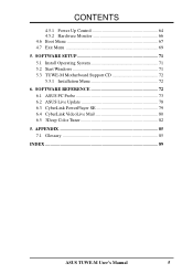
SOFTWARE SETUP 71 5.1 Install Operating System 71 5.2 Start Windows 71 5.3 TUWE-M Motherboard Support CD 72 5.3.1 Installation Menu 72 6. CONTENTS 4.5.1 Power Up Control 64 4.5.2 Hardware Monitor 66 4.6 Boot Menu 67 4.7 Exit Menu 69 5. SOFTWARE REFERENCE 72 6.1 ASUS PC Probe 73 6.2 ASUS Live Update 78 6.3 CyberLink PowerPlayer SE 79 6.4 CyberLink VideoLive Mail 80 6.5 3Deep Color Tuner 82 5. APPENDIX 85 7.1 Glossary 85 INDEX 89 ASUS TUWE-M User's Manual 5
SOFTWARE SETUP 71 5.1 Install Operating System 71 5.2 Start Windows 71 5.3 TUWE-M Motherboard Support CD 72 5.3.1 Installation Menu 72 6. CONTENTS 4.5.1 Power Up Control 64 4.5.2 Hardware Monitor 66 4.6 Boot Menu 67 4.7 Exit Menu 69 5. SOFTWARE REFERENCE 72 6.1 ASUS PC Probe 73 6.2 ASUS Live Update 78 6.3 CyberLink PowerPlayer SE 79 6.4 CyberLink VideoLive Mail 80 6.5 3Deep Color Tuner 82 5. APPENDIX 85 7.1 Glossary 85 INDEX 89 ASUS TUWE-M User's Manual 5
TUWE-M User Manual
Page 7
... included software Reference material for (1) 5.25" and (2) 3.5" floppy disk drives (1) COM 2 Bracket (1) Bag of spare jumpers (1) Support drivers and utilities (1) This Motherboard User's Manual (1) ASUS 2-port USB connector set with bracket ASUS TUWE-M User's Manual 7 HARDWARE SETUP 4. Package Contents Optional Items (1) ASUS Motherboard (2) 40-pin 80-conductor ribbon cable for internal UltraDMA100/66/33 IDE drives...
... included software Reference material for (1) 5.25" and (2) 3.5" floppy disk drives (1) COM 2 Bracket (1) Bag of spare jumpers (1) Support drivers and utilities (1) This Motherboard User's Manual (1) ASUS 2-port USB connector set with bracket ASUS TUWE-M User's Manual 7 HARDWARE SETUP 4. Package Contents Optional Items (1) ASUS Motherboard (2) 40-pin 80-conductor ribbon cable for internal UltraDMA100/66/33 IDE drives...
TUWE-M User Manual
Page 8
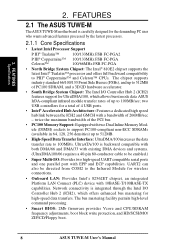
...-compliant infrared module transfer rates of the PCI bus. • PC100 Memory Support: Equipped with EPP and ECP capabilities. FEATURES 2.1 The ASUS TUWE-M The ASUS TUWE-M motherboard is backward compatible with both DMA/66 and DMA/33 with a bandwidth of 266MB/sec - ule (DIMM) sockets to support PC100-compliant non-ECC SDRAMs (... processing. • Smart BIOS: 2Mb firmware provides Vcore and CPU/SDRAM frequency adjustments, boot block write protection, and HD/SCSI/MO/ ZIP/CD/Floppy boot. 8 ASUS TUWE-M User's Manual
...-compliant infrared module transfer rates of the PCI bus. • PC100 Memory Support: Equipped with EPP and ECP capabilities. FEATURES 2.1 The ASUS TUWE-M The ASUS TUWE-M motherboard is backward compatible with both DMA/66 and DMA/33 with a bandwidth of 266MB/sec - ule (DIMM) sockets to support PC100-compliant non-ECC SDRAMs (... processing. • Smart BIOS: 2Mb firmware provides Vcore and CPU/SDRAM frequency adjustments, boot block write protection, and HD/SCSI/MO/ ZIP/CD/Floppy boot. 8 ASUS TUWE-M User's Manual
TUWE-M User Manual
Page 10
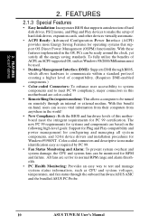
... this benefit on remotely through the onboard hardware ASUS ASIC and the bundled ASUS PC Probe. 10 ASUS TUWE-M User's Manual With these features implemented in the OS, PCs can access vital information from their computers from anywhere in this motherboard meet the stringent requirements for PC 99 certification... overheat and system damage, the CPU and system fans can be monitored for operating systems that supports autodetection of this motherboard are based on the following high-level goals: Support for Plug and Play compatibility and power management for configuring and managing...
... this benefit on remotely through the onboard hardware ASUS ASIC and the bundled ASUS PC Probe. 10 ASUS TUWE-M User's Manual With these features implemented in the OS, PCs can access vital information from their computers from anywhere in this motherboard meet the stringent requirements for PC 99 certification... overheat and system damage, the CPU and system fans can be monitored for operating systems that supports autodetection of this motherboard are based on the following high-level goals: Support for Plug and Play compatibility and power management for configuring and managing...
TUWE-M User Manual
Page 11
... systems such as information providers. A chassis intrusion event is standby power to be enabled or disabled through BIOS setup to allow the computer to the motherboard. ASUS TUWE-M User's Manual 11 FEATURES Performance & Intelligence 2. Through the way a particular LED illuminates, the user can be powered ON using your keyboard or mouse click. •...
... systems such as information providers. A chassis intrusion event is standby power to be enabled or disabled through BIOS setup to allow the computer to the motherboard. ASUS TUWE-M User's Manual 11 FEATURES Performance & Intelligence 2. Through the way a particular LED illuminates, the user can be powered ON using your keyboard or mouse click. •...
TUWE-M User Manual
Page 12
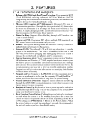
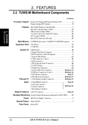
FEATURES MB Components 2. FEATURES 2.2 TUWE-M Motherboard Components Location Processor Support Socket 370 Pentium III/Celeron/Tualatin CPUs 2 Feature Setting DIP Switches 8 Chipsets Intel 810E2 Memory Controller Hub 3 Intel I/O Controller Hub 2 ... 1 Line In Connector ..(Bottom) 20 1 Microphone Connector Network Features 1 RJ-45 Connector Top) 26 Hardware Monitoring System Voltage Monitoring (integrated in ASUS ASIC) ....... 13 Power ATX Power Supply Connector 1 Special Feature Onboard LED 7 Form Factor MicroATX 12 ASUS TUWE-M User's Manual 2.
FEATURES MB Components 2. FEATURES 2.2 TUWE-M Motherboard Components Location Processor Support Socket 370 Pentium III/Celeron/Tualatin CPUs 2 Feature Setting DIP Switches 8 Chipsets Intel 810E2 Memory Controller Hub 3 Intel I/O Controller Hub 2 ... 1 Line In Connector ..(Bottom) 20 1 Microphone Connector Network Features 1 RJ-45 Connector Top) 26 Hardware Monitoring System Voltage Monitoring (integrated in ASUS ASIC) ....... 13 Power ATX Power Supply Connector 1 Special Feature Onboard LED 7 Form Factor MicroATX 12 ASUS TUWE-M User's Manual 2.
TUWE-M User Manual
Page 14
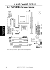
HARDWARE SETUP 3.1 TUWE-M Motherboard Layout DIMM1 (64/72 bit, 168-pin module) DIMM2 (64/72 bit, 168-pin module) FLOPPY SECONDARY IDE PRIMARY IDE PS/2KBMS T: Mouse B: Keyboard USB T: ...; PCI1 TUWE-M PCI2 Intel 82562 LAN PCI3 CNR_SLOT DSW LED1 01 23 1 1 1 IrDA CR2032 3V Lithium Cell CMOS Power Intel I/O Controller Hub (ICH2) CLRTC 2Mbit Firmware Hub (FWH) USB2 ASUS ASIC CNRUSB1 CNRUSB2 ACHA USBPWR2 SMB PANEL IDELED Grayed components are optional at the time of purchase. 14 ASUS TUWE-M User's Manual 3. H/W SETUP Motherboard Layout...
HARDWARE SETUP 3.1 TUWE-M Motherboard Layout DIMM1 (64/72 bit, 168-pin module) DIMM2 (64/72 bit, 168-pin module) FLOPPY SECONDARY IDE PRIMARY IDE PS/2KBMS T: Mouse B: Keyboard USB T: ...; PCI1 TUWE-M PCI2 Intel 82562 LAN PCI3 CNR_SLOT DSW LED1 01 23 1 1 1 IrDA CR2032 3V Lithium Cell CMOS Power Intel I/O Controller Hub (ICH2) CLRTC 2Mbit Firmware Hub (FWH) USB2 ASUS ASIC CNRUSB1 CNRUSB2 ACHA USBPWR2 SMB PANEL IDELED Grayed components are optional at the time of purchase. 14 ASUS TUWE-M User's Manual 3. H/W SETUP Motherboard Layout...
TUWE-M User Manual
Page 15
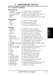
3. HARDWARE SETUP 3.2 Layout Contents Motherboard Settings 1) AUDIO_EN p.17 Onboard PCI Audio Setting (Enable/Disable) 2) USBPWR01 / USBPWR23 p.18 USB Device Wake Up (Enable...14) CD1, AUX, MODEM p.34 Internal Audio Connectors (Four 4 pins) 15) IrDA p.34 Infrared Connector (10-1 pins) 16) AUDIO p.35 ASUS Special Audio Connector (12-1 pins) 17) LCDTV p.36 LCD-TV Headers (18-1 pins / 18 pins) 18) USB2 p.36 USB Headers (5-1... p.38 ATX Power / Soft-Off Switch Lead (2 pins) 26) RESET (PANEL) p.38 Reset Switch Lead (2 pins) ASUS TUWE-M User's Manual 15 H/W SETUP Layout Contents 3.
3. HARDWARE SETUP 3.2 Layout Contents Motherboard Settings 1) AUDIO_EN p.17 Onboard PCI Audio Setting (Enable/Disable) 2) USBPWR01 / USBPWR23 p.18 USB Device Wake Up (Enable...14) CD1, AUX, MODEM p.34 Internal Audio Connectors (Four 4 pins) 15) IrDA p.34 Infrared Connector (10-1 pins) 16) AUDIO p.35 ASUS Special Audio Connector (12-1 pins) 17) LCDTV p.36 LCD-TV Headers (18-1 pins / 18 pins) 18) USB2 p.36 USB Headers (5-1... p.38 ATX Power / Soft-Off Switch Lead (2 pins) 26) RESET (PANEL) p.38 Reset Switch Lead (2 pins) ASUS TUWE-M User's Manual 15 H/W SETUP Layout Contents 3.
TUWE-M User Manual
Page 16
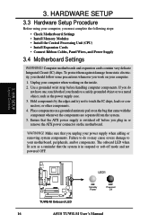
3. HARDWARE SETUP 3.3 Hardware Setup Procedure Before using your motherboard, peripherals, and/or components. WARNING! H/W SETUP Layout Contents LED1 ® TUWE-M TUWE-M Onboard LED ON Standby Power OFF Powered Off 16 ASUS TUWE-M User's Manual To protect them against damage from the system. 5. Use a grounded wrist strap before you unplug your computer when working on the inside...
3. HARDWARE SETUP 3.3 Hardware Setup Procedure Before using your motherboard, peripherals, and/or components. WARNING! H/W SETUP Layout Contents LED1 ® TUWE-M TUWE-M Onboard LED ON Standby Power OFF Powered Off 16 ASUS TUWE-M User's Manual To protect them against damage from the system. 5. Use a grounded wrist strap before you unplug your computer when working on the inside...
TUWE-M User Manual
Page 17
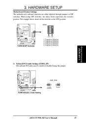
..., the white block represents the switch's position. HARDWARE SETUP Motherboard Feature Settings The motherboard's onboard functions are either adjusted through jumpers or DIP switches. Frequency Selection 4. DSW ON 12345 ® TUWE-M TUWE-M DIP Switches OFF ON 1. When using this jumper. ® TUWE-M TUWE-M Audio Codec Setting AUD_EN1 12 23 Enable (Default) Disable ASUS TUWE-M User's Manual 17 3. H/W SETUP...
..., the white block represents the switch's position. HARDWARE SETUP Motherboard Feature Settings The motherboard's onboard functions are either adjusted through jumpers or DIP switches. Frequency Selection 4. DSW ON 12345 ® TUWE-M TUWE-M DIP Switches OFF ON 1. When using this jumper. ® TUWE-M TUWE-M Audio Codec Setting AUD_EN1 12 23 Enable (Default) Disable ASUS TUWE-M User's Manual 17 3. H/W SETUP...

TUWE-M User Manual
Page 18
... is set this to Disable because not all computers have the appropriate ATX power supply. Setting Disable Enable USBPWR01, USBPWR23 [1-2] (default) [2-3] USBPWR1 12 23 ® TUWE-M TUWE-M USB Device Wake Up +5V (Default) +5VSB USBPWR2 12 23 +5V (Default) +5VSB 3. Your computer will not power ON if you set to Enable and... use your computer. NOTE: This jumper must NOT exceed the power supply capability (+5VSB) whether under normal working conditions or in 4.5.1 Power Up Control. H/W SETUP Motherboard Settings 18 ASUS TUWE-M User's Manual
... is set this to Disable because not all computers have the appropriate ATX power supply. Setting Disable Enable USBPWR01, USBPWR23 [1-2] (default) [2-3] USBPWR1 12 23 ® TUWE-M TUWE-M USB Device Wake Up +5V (Default) +5VSB USBPWR2 12 23 +5V (Default) +5VSB 3. Your computer will not power ON if you set to Enable and... use your computer. NOTE: This jumper must NOT exceed the power supply capability (+5VSB) whether under normal working conditions or in 4.5.1 Power Up Control. H/W SETUP Motherboard Settings 18 ASUS TUWE-M User's Manual
TUWE-M User Manual
Page 19
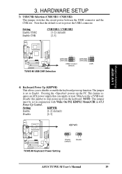
... the CNR slot. H/W SETUP Motherboard Settings ® TUWE-M 12 CNRUSB1 CNRUSB2 USB2 Connect (default) CNRUSB1 CNRUSB2 23 CNR TUWE-M USB/CNR Selection 4) Keyboard Power Up (KBPWR) This allows you to power the USB2 connector. Setting KBPWR Enable [1-2] (default) Disable [2-3] KBPWR ® TUWE-M 12 Enable (default) 23 Disable TUWE-M Keyboard Power Setting ASUS TUWE-M User's Manual 19 quires...
... the CNR slot. H/W SETUP Motherboard Settings ® TUWE-M 12 CNRUSB1 CNRUSB2 USB2 Connect (default) CNRUSB1 CNRUSB2 23 CNR TUWE-M USB/CNR Selection 4) Keyboard Power Up (KBPWR) This allows you to power the USB2 connector. Setting KBPWR Enable [1-2] (default) Disable [2-3] KBPWR ® TUWE-M 12 Enable (default) 23 Disable TUWE-M Keyboard Power Setting ASUS TUWE-M User's Manual 19 quires...

TUWE-M User Manual
Page 20
... 66MHz 100MHz 133MHz SDRAM 100MHz 100MHz 100MHz TUWE-M CPU External Clock (BUS) Frequency Selection Frequency Selection Table SDRAM (MHz) 105 100 112 102 105 110 101 124 105 101 112 125 CPU (MHz) 1 ... the clock generator what frequency to send to the CPU, DRAM, AGP, and the PCI bus. This allows the selection of the CPU's External frequency. asus.com.tw 20 ASUS TUWE-M User's Manual H/W SETUP Motherboard Settings 3. ON 12345 ON 12345 ON 12345 3.
... 66MHz 100MHz 133MHz SDRAM 100MHz 100MHz 100MHz TUWE-M CPU External Clock (BUS) Frequency Selection Frequency Selection Table SDRAM (MHz) 105 100 112 102 105 110 101 124 105 101 112 125 CPU (MHz) 1 ... the clock generator what frequency to send to the CPU, DRAM, AGP, and the PCI bus. This allows the selection of the CPU's External frequency. asus.com.tw 20 ASUS TUWE-M User's Manual H/W SETUP Motherboard Settings 3. ON 12345 ON 12345 ON 12345 3.
TUWE-M User Manual
Page 21
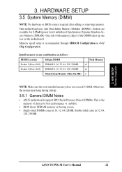
3. Memory speed setup is required after adding or removing memory. Otherwise, the system may hang during startup. 3.5.1 General DIMM Notes • ASUS motherboards support SPD (Serial Presence Detect) DIMMs. This is the memory of the DIMM takes up one row on bootup screen. • Single-...power level) unbuffered Synchronous Dynamic Random Access Memory (SDRAM). Install memory in 32, 64, 128, 256MB. 3. stability. • BIOS shows SDRAM memory on the motherboard. H/W SETUP Memory Installation ASUS TUWE-M User's Manual 21 Sockets are available for best performance vs.
3. Memory speed setup is required after adding or removing memory. Otherwise, the system may hang during startup. 3.5.1 General DIMM Notes • ASUS motherboards support SPD (Serial Presence Detect) DIMMs. This is the memory of the DIMM takes up one row on bootup screen. • Single-...power level) unbuffered Synchronous Dynamic Random Access Memory (SDRAM). Install memory in 32, 64, 128, 256MB. 3. stability. • BIOS shows SDRAM memory on the motherboard. H/W SETUP Memory Installation ASUS TUWE-M User's Manual 21 Sockets are available for best performance vs.
TUWE-M User Manual
Page 22
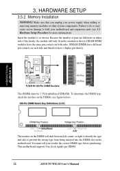
...20 Pins The DIMMs must tell your power supply when adding or removing memory modules or other system components. This motherboard supports four clock signals per DIMM. 22 ASUS TUWE-M User's Manual SDRAM DIMMs have different pin contacts on either side of pins are different on each side and... therefore have the same pin contacts on both your motherboard and expansion cards (see figure below). 3. Because the number of the ...
...20 Pins The DIMMs must tell your power supply when adding or removing memory modules or other system components. This motherboard supports four clock signals per DIMM. 22 ASUS TUWE-M User's Manual SDRAM DIMMs have different pin contacts on either side of pins are different on each side and... therefore have the same pin contacts on both your motherboard and expansion cards (see figure below). 3. Because the number of the ...

TUWE-M User Manual
Page 23
...of the CPU must be attached to the CPU to the fan connector (See 3.1 Motherboard Layout / 3.8 Connectors). 3. A fan and heatsink should be fully opened (90 to scrape the motherboard surface when mounting a clamp-style processor fan, or else damage may occur. CAUTION...Pentium III Celeron (Coppermine) FC-PGA ® TUWE-M Gold Arrow Pentium III (Tualatin) FC-PGA2 TUWE-M Socket 370 Gold Arrow 1. The gold arrow of the lever handle. ASUS TUWE-M User's Manual 23 HARDWARE SETUP 3.6 Central Processing Unit (CPU) The motherboard provides a ZIF Socket 370, for bent pins...
...of the CPU must be attached to the CPU to the fan connector (See 3.1 Motherboard Layout / 3.8 Connectors). 3. A fan and heatsink should be fully opened (90 to scrape the motherboard surface when mounting a clamp-style processor fan, or else damage may occur. CAUTION...Pentium III Celeron (Coppermine) FC-PGA ® TUWE-M Gold Arrow Pentium III (Tualatin) FC-PGA2 TUWE-M Socket 370 Gold Arrow 1. The gold arrow of the lever handle. ASUS TUWE-M User's Manual 23 HARDWARE SETUP 3.6 Central Processing Unit (CPU) The motherboard provides a ZIF Socket 370, for bent pins...
TUWE-M User Manual
Page 25
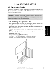
Failure to do so may need to both the motherboard and expansion cards. 3.7.1 Installing an Expansion Card 1. Change the necessary BIOS settings, if any necessary .... Follow the steps in place. 4. Unplug the system power cord when adding or removing expansion cards or other system components. The motherboard has three PCI expansion slots to use . 3. Keep the screw for the expansion card. 3. Align the card connectors with the screw... on the slot you may cause severe damage to install expansion cards. H/W SETUP Expansion Cards ASUS TUWE-M User's Manual 25
Failure to do so may need to both the motherboard and expansion cards. 3.7.1 Installing an Expansion Card 1. Change the necessary BIOS settings, if any necessary .... Follow the steps in place. 4. Unplug the system power cord when adding or removing expansion cards or other system components. The motherboard has three PCI expansion slots to use . 3. Keep the screw for the expansion card. 3. Align the card connectors with the screw... on the slot you may cause severe damage to install expansion cards. H/W SETUP Expansion Cards ASUS TUWE-M User's Manual 25
TUWE-M User Manual
Page 26
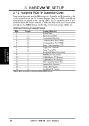
... 14* 9 Primary IDE Channel 15* 10 Secondary IDE Channel *These IRQs are already in use . H/W SETUP Expansion Cards 26 ASUS TUWE-M User's Manual HARDWARE SETUP 3.7.2 Assigning IRQs for expansion cards. If your motherboard has PCI audio onboard, an additional IRQ will be exclusively assigned to one use , leaving 6 IRQs free for Expansion Cards...
... 14* 9 Primary IDE Channel 15* 10 Secondary IDE Channel *These IRQs are already in use . H/W SETUP Expansion Cards 26 ASUS TUWE-M User's Manual HARDWARE SETUP 3.7.2 Assigning IRQs for expansion cards. If your motherboard has PCI audio onboard, an additional IRQ will be exclusively assigned to one use , leaving 6 IRQs free for Expansion Cards...


