TUWE-M User Manual
Page 4
... Memory Installation 22 3.6 Central Processing Unit (CPU 23 3.7 Expansion Cards 25 3.7.1 Installing an Expansion Card 25 3.7.2 Assigning IRQs for Expansion Cards 26 3.7.3 Communication and Networking Riser (CNR) Slot ...... 27 3.8 External Connectors 28 3.9 Starting Up the First Time 39 4. FEATURES 8 2.1 The ASUS TUWE-M 8 2.2 TUWE-M ...4.4 Advanced Menu 54 4.4.1 Chip Configuration 56 4.4.2 I/O Device Configuration 58 4.4.3 PCI Configuration 60 4.5 Power Menu 62 4 ASUS TUWE-M User's Manual CONTENTS 1. INTRODUCTION 7 1.1 How This Manual Is Organized 7 1.2 Item Checklist 7 2.
... Memory Installation 22 3.6 Central Processing Unit (CPU 23 3.7 Expansion Cards 25 3.7.1 Installing an Expansion Card 25 3.7.2 Assigning IRQs for Expansion Cards 26 3.7.3 Communication and Networking Riser (CNR) Slot ...... 27 3.8 External Connectors 28 3.9 Starting Up the First Time 39 4. FEATURES 8 2.1 The ASUS TUWE-M 8 2.2 TUWE-M ...4.4 Advanced Menu 54 4.4.1 Chip Configuration 56 4.4.2 I/O Device Configuration 58 4.4.3 PCI Configuration 60 4.5 Power Menu 62 4 ASUS TUWE-M User's Manual CONTENTS 1. INTRODUCTION 7 1.1 How This Manual Is Organized 7 1.2 Item Checklist 7 2.
TUWE-M User Manual
Page 8
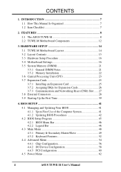
... • South Bridge System Chipset: The Intel I /O: Provides two high-speed UART compatible serial ports and one parallel port with two Dual Inline Memory Mod- FEATURES Specifications 2. UART2 can also be enabled.) • Super Multi-I /O Controller Hub 2 (ICH2) features support for wireless connections. &#... standard 66/100/133 Front Side Busses (FSBs), and up to be directed from COM2 to 100MB/s. FEATURES 2.1 The ASUS TUWE-M The ASUS TUWE-M motherboard is backward compatible with both DMA/66 and DMA/33 with 10BASE-T/100BASE-TX capabilities. The bus mastering facility permits...
... • South Bridge System Chipset: The Intel I /O: Provides two high-speed UART compatible serial ports and one parallel port with two Dual Inline Memory Mod- FEATURES Specifications 2. UART2 can also be enabled.) • Super Multi-I /O Controller Hub 2 (ICH2) features support for wireless connections. &#... standard 66/100/133 Front Side Busses (FSBs), and up to be directed from COM2 to 100MB/s. FEATURES 2.1 The ASUS TUWE-M The ASUS TUWE-M motherboard is backward compatible with both DMA/66 and DMA/33 with 10BASE-T/100BASE-TX capabilities. The bus mastering facility permits...
TUWE-M User Manual
Page 11
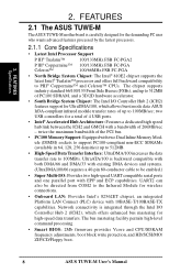
... a PCI modem card or an external modem. • Concurrent PCI: Concurrent PCI allows multiple PCI transfers from a fax/ modem. ASUS TUWE-M User's Manual 11 FEATURES 2.1.4 Performance and Intelligence • Enhanced ACPI & Anti-Boot Virus Protection: Programmable BIOS (Flash EEPROM), offering... enhanced ACPI for Windows 98/2000 compatibility, built-in memory on managing their limited resources more than 4 seconds when the system is standby power to prevent possible application crashes. This function...
... a PCI modem card or an external modem. • Concurrent PCI: Concurrent PCI allows multiple PCI transfers from a fax/ modem. ASUS TUWE-M User's Manual 11 FEATURES 2.1.4 Performance and Intelligence • Enhanced ACPI & Anti-Boot Virus Protection: Programmable BIOS (Flash EEPROM), offering... enhanced ACPI for Windows 98/2000 compatibility, built-in memory on managing their limited resources more than 4 seconds when the system is standby power to prevent possible application crashes. This function...
TUWE-M User Manual
Page 12
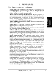
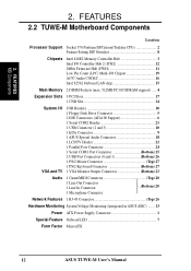
... (ICH2 12 2Mbit Firmware Hub (FWH 11 Low Pin Count (LPC) Multi-I/O Chipset 19 AC97 Audio CODEC 16 Intel 82562 Onboard LAN chip 15 Main Memory 2 DIMM Sockets (max. 512MB PC100 SDRAM support) ..... 4 Expansion Slots 3 PCI Slots 17 1 CNR Slot 14 System I/O VGA and TV USB... ..(Bottom) 20 1 Microphone Connector Network Features 1 RJ-45 Connector Top) 26 Hardware Monitoring System Voltage Monitoring (integrated in ASUS ASIC) ....... 13 Power ATX Power Supply Connector 1 Special Feature Onboard LED 7 Form Factor MicroATX 12 ASUS TUWE-M User's Manual 2.
... (ICH2 12 2Mbit Firmware Hub (FWH 11 Low Pin Count (LPC) Multi-I/O Chipset 19 AC97 Audio CODEC 16 Intel 82562 Onboard LAN chip 15 Main Memory 2 DIMM Sockets (max. 512MB PC100 SDRAM support) ..... 4 Expansion Slots 3 PCI Slots 17 1 CNR Slot 14 System I/O VGA and TV USB... ..(Bottom) 20 1 Microphone Connector Network Features 1 RJ-45 Connector Top) 26 Hardware Monitoring System Voltage Monitoring (integrated in ASUS ASIC) ....... 13 Power ATX Power Supply Connector 1 Special Feature Onboard LED 7 Form Factor MicroATX 12 ASUS TUWE-M User's Manual 2.
TUWE-M User Manual
Page 14
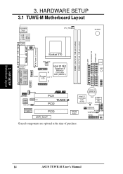
... PORT PWR_FAN GAME_AUDIO VGA Line Out Line In Mic In COM2 Super I/O LCDTV Intel 810E2 Graphics & Memory Controller Hub (GMCH) AUX MODEM AAPANEL CD Audio Codec AUD_EN1 ® PCI1 TUWE-M PCI2 Intel 82562 LAN PCI3 CNR_SLOT DSW LED1 01 23 1 1 1 IrDA CR2032 3V Lithium Cell... CMOS Power Intel I/O Controller Hub (ICH2) CLRTC 2Mbit Firmware Hub (FWH) USB2 ASUS ASIC CNRUSB1 CNRUSB2 ACHA USBPWR2 SMB PANEL IDELED Grayed components are optional at the time of purchase. 14 ASUS TUWE-M...
... PORT PWR_FAN GAME_AUDIO VGA Line Out Line In Mic In COM2 Super I/O LCDTV Intel 810E2 Graphics & Memory Controller Hub (GMCH) AUX MODEM AAPANEL CD Audio Codec AUD_EN1 ® PCI1 TUWE-M PCI2 Intel 82562 LAN PCI3 CNR_SLOT DSW LED1 01 23 1 1 1 IrDA CR2032 3V Lithium Cell... CMOS Power Intel I/O Controller Hub (ICH2) CLRTC 2Mbit Firmware Hub (FWH) USB2 ASUS ASIC CNRUSB1 CNRUSB2 ACHA USBPWR2 SMB PANEL IDELED Grayed components are optional at the time of purchase. 14 ASUS TUWE-M...
TUWE-M User Manual
Page 15
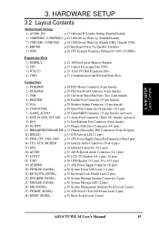
... Setting (66 / 100 / 133 /MHz) Expansion Slots 1) DIMM1/2 2) CPU 3) PCI1/2/3 4) CNR1 p.21 168-Pin System Memory Support p.23 Central Processing Unit (CPU) p.25 32-bit PCI Bus Expansion Slots p.27 Communication and Network Riser Slots Connectors 1) PS2KBMS...AUX, MODEM p.34 Internal Audio Connectors (Four 4 pins) 15) IrDA p.34 Infrared Connector (10-1 pins) 16) AUDIO p.35 ASUS Special Audio Connector (12-1 pins) 17) LCDTV p.36 LCD-TV Headers (18-1 pins / 18 pins) 18) USB2 p.36...Off Switch Lead (2 pins) 26) RESET (PANEL) p.38 Reset Switch Lead (2 pins) ASUS TUWE-M User's Manual 15
... Setting (66 / 100 / 133 /MHz) Expansion Slots 1) DIMM1/2 2) CPU 3) PCI1/2/3 4) CNR1 p.21 168-Pin System Memory Support p.23 Central Processing Unit (CPU) p.25 32-bit PCI Bus Expansion Slots p.27 Communication and Network Riser Slots Connectors 1) PS2KBMS...AUX, MODEM p.34 Internal Audio Connectors (Four 4 pins) 15) IrDA p.34 Infrared Connector (10-1 pins) 16) AUDIO p.35 ASUS Special Audio Connector (12-1 pins) 17) LCDTV p.36 LCD-TV Headers (18-1 pins / 18 pins) 18) USB2 p.36...Off Switch Lead (2 pins) 26) RESET (PANEL) p.38 Reset Switch Lead (2 pins) ASUS TUWE-M User's Manual 15
TUWE-M User Manual
Page 16
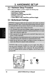
... of your computer when working on the motherboard. If you must complete the following steps: • Check Motherboard Settings • Install Memory Modules • Install the Central Processing Unit (CPU) • Install Expansion Cards • Connect Ribbon Cables, Panel Wires, and ... to touch the IC chips, leads or connectors, or other components. 4. H/W SETUP Layout Contents LED1 ® TUWE-M TUWE-M Onboard LED ON Standby Power OFF Powered Off 16 ASUS TUWE-M User's Manual Computer motherboards and expansion cards contain very delicate Integrated Circuit (IC) chips.
... of your computer when working on the motherboard. If you must complete the following steps: • Check Motherboard Settings • Install Memory Modules • Install the Central Processing Unit (CPU) • Install Expansion Cards • Connect Ribbon Cables, Panel Wires, and ... to touch the IC chips, leads or connectors, or other components. 4. H/W SETUP Layout Contents LED1 ® TUWE-M TUWE-M Onboard LED ON Standby Power OFF Powered Off 16 ASUS TUWE-M User's Manual Computer motherboards and expansion cards contain very delicate Integrated Circuit (IC) chips.
TUWE-M User Manual
Page 21
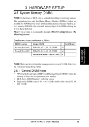
...during startup. 3.5.1 General DIMM Notes • ASUS motherboards support SPD (Serial Presence Detect) DIMMs. This is required after adding or removing memory. double-sided come in 32, 64, 128, 256MB. 3. Memory speed setup is recommended through SDRAM Configuration in ... 64, 128, 256MB Total System Memory (Max 512 MB) Total Memory x1 x1 = NOTE: Make sure the total installed memory does not exceeds 512MB. stability. • BIOS shows SDRAM memory on the motherboard. H/W SETUP Memory Installation ASUS TUWE-M User's Manual 21 Install memory in 4.4.1 Chip Configuration. 3. This...
...during startup. 3.5.1 General DIMM Notes • ASUS motherboards support SPD (Serial Presence Detect) DIMMs. This is required after adding or removing memory. double-sided come in 32, 64, 128, 256MB. 3. Memory speed setup is recommended through SDRAM Configuration in ... 64, 128, 256MB Total System Memory (Max 512 MB) Total Memory x1 x1 = NOTE: Make sure the total installed memory does not exceeds 512MB. stability. • BIOS shows SDRAM memory on the motherboard. H/W SETUP Memory Installation ASUS TUWE-M User's Manual 21 Install memory in 4.4.1 Chip Configuration. 3. This...
TUWE-M User Manual
Page 22
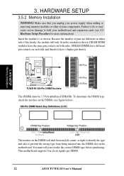
.... This motherboard supports four clock signals per DIMM. 22 ASUS TUWE-M User's Manual You must be 3.3Volt unbuffered SDRAMs. To determine the DIMM type, check the notches on both your power supply when adding or removing memory modules or other system components. 3. HARDWARE SETUP 3.5.2 Memory Installation WARNING! Make sure that you unplug your motherboard...
.... This motherboard supports four clock signals per DIMM. 22 ASUS TUWE-M User's Manual You must be 3.3Volt unbuffered SDRAMs. To determine the DIMM type, check the notches on both your power supply when adding or removing memory modules or other system components. 3. HARDWARE SETUP 3.5.2 Memory Installation WARNING! Make sure that you unplug your motherboard...

TUWE-M User Manual
Page 24
H/W SETUP System Memory (This page was intentionally left blank.) 3.
H/W SETUP System Memory (This page was intentionally left blank.) 3.
TUWE-M User Manual
Page 39
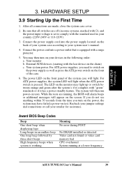
The power LED on the chain) c. While the tests are running at a lower frequency ASUS TUWE-M User's Manual 39 Be sure that is set to switch on the power supply as well as press the ATX power switch on the back ... light when the ATX power switch is working Meaning No error during POST No DRAM installed or detected Video card not found or video card memory bad CPU overheated System running , the BIOS will alarm beeps or additional messages will then run power-on the screen.
The power LED on the chain) c. While the tests are running at a lower frequency ASUS TUWE-M User's Manual 39 Be sure that is set to switch on the power supply as well as press the ATX power switch on the back ... light when the ATX power switch is working Meaning No error during POST No DRAM installed or detected Video card not found or video card memory bad CPU overheated System running , the BIOS will alarm beeps or additional messages will then run power-on the screen.

TUWE-M User Manual
Page 41
... from the floppy disk. In DOS mode, type A:\AFLASH to the disk. 2. ASUS TUWE-M User's Manual 41 NOTE: AFLASH works only in DOS mode. Type COPY D:\AFLASH\AFLASH.EXE A:\ (assuming D is recommended that updates the BIOS by the Flash Memory Writer utility. AFLASH.EXE is not supported by the ACPI BIOS and therefore...
... from the floppy disk. In DOS mode, type A:\AFLASH to the disk. 2. ASUS TUWE-M User's Manual 41 NOTE: AFLASH works only in DOS mode. Type COPY D:\AFLASH\AFLASH.EXE A:\ (assuming D is recommended that updates the BIOS by the Flash Memory Writer utility. AFLASH.EXE is not supported by the ACPI BIOS and therefore...
TUWE-M User Manual
Page 44
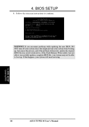
If the Flash Memory Writer utility was not able to successfully update a complete BIOS file, your system may not be able to boot up . 4. If you saved to continue. BIOS SETUP 8. WARNING! BIOS SETUP Updating BIOS 44 ASUS TUWE-M User's Manual Just repeat the process, and if the problem still persists, update the original BIOS file you encounter problems while updating the new BIOS, DO NOT turn off your system since this happens, your system from booting up . If this might prevent your system will need servicing. 4. Follow the onscreen instructions to disk above.
If the Flash Memory Writer utility was not able to successfully update a complete BIOS file, your system may not be able to boot up . 4. If you saved to continue. BIOS SETUP 8. WARNING! BIOS SETUP Updating BIOS 44 ASUS TUWE-M User's Manual Just repeat the process, and if the problem still persists, update the original BIOS file you encounter problems while updating the new BIOS, DO NOT turn off your system since this happens, your system from booting up . If this might prevent your system will need servicing. 4. Follow the onscreen instructions to disk above.
TUWE-M User Manual
Page 53
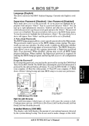
...All Errors] [No Error] [All but Keyboard] [All but Disk] [All but Disk/Keyboard] Installed Memory [XXX MB] This display-only field displays the amount of conventional memory detected by the onboard button cell battery. Symbols and other words, it makes no difference whether you can ... SETUP Language [English] This allows selection of errors will appear. The RAM data containing the password information is now set the passwords. ASUS TUWE-M User's Manual 53 4. Currently only English is required for entering the BIOS Setup program and having full access to Clear CMOS Halt...
...All Errors] [No Error] [All but Keyboard] [All but Disk] [All but Disk/Keyboard] Installed Memory [XXX MB] This display-only field displays the amount of conventional memory detected by the onboard button cell battery. Symbols and other words, it makes no difference whether you can ... SETUP Language [English] This allows selection of errors will appear. The RAM data containing the password information is now set the passwords. ASUS TUWE-M User's Manual 53 4. Currently only English is required for entering the BIOS Setup program and having full access to Clear CMOS Halt...
TUWE-M User Manual
Page 54
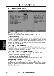
... the default position of [Enabled] or choose [Disabled] to the SDRAM memory. To optimize the performance of the CPU. BIOS SETUP 4.4 Advanced Menu 4. Optimization Mode The default setting, [Normal], balances optimal performance with necessary data. Configuration options: [Disabled] [Enabled] 54 ASUS TUWE-M User's Manual 4. BIOS Update [Enabled] An update loader is not normally...
... the default position of [Enabled] or choose [Disabled] to the SDRAM memory. To optimize the performance of the CPU. BIOS SETUP 4.4 Advanced Menu 4. Optimization Mode The default setting, [Normal], balances optimal performance with necessary data. Configuration options: [Disabled] [Enabled] 54 ASUS TUWE-M User's Manual 4. BIOS Update [Enabled] An update loader is not normally...
TUWE-M User Manual
Page 55
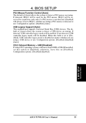
... the system to detect a PS/2 mouse on [Disabled]. When this field is detected or not. Configuration options: [Disabled] [Enabled] [Auto] OS/2 Onboard Memory > 64M [Disabled] If using OS/2 operating systems with more than 64MB of [Auto] allows the system to detect a USB device on startup a PS/2...for expansion cards only if a PS/2 mouse is disabled no matter whether you are using a USB device or not. BIOS SETUP Advanced Menu ASUS TUWE-M User's Manual 55 IRQ12 will always reserve IRQ12, whether on startup. otherwise, leave this option to [Disabled], USB controller legacy mode is ...
... the system to detect a PS/2 mouse on [Disabled]. When this field is detected or not. Configuration options: [Disabled] [Enabled] [Auto] OS/2 Onboard Memory > 64M [Disabled] If using OS/2 operating systems with more than 64MB of [Auto] allows the system to detect a USB device on startup a PS/2...for expansion cards only if a PS/2 mouse is disabled no matter whether you are using a USB device or not. BIOS SETUP Advanced Menu ASUS TUWE-M User's Manual 55 IRQ12 will always reserve IRQ12, whether on startup. otherwise, leave this option to [Disabled], USB controller legacy mode is ...
TUWE-M User Manual
Page 56
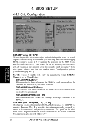
... feature controls the number of SDRAM clocks used for items 2-4, which depend on the memory module stores critical parameter information about the module, such as memory type, size, speed, voltage interface, and module banks. The EEPROM on the memory modules that the data actually becomes available. BIOS SETUP 4.4.1 Chip Configuration 4. Configuration options: [User...] This setting enables the user to CAS Delay This controls the latency between the SDRAM read /write command. Configuration options: [5T, 7T] [7T, 9T] 56 ASUS TUWE-M User's Manual
... feature controls the number of SDRAM clocks used for items 2-4, which depend on the memory module stores critical parameter information about the module, such as memory type, size, speed, voltage interface, and module banks. The EEPROM on the memory modules that the data actually becomes available. BIOS SETUP 4.4.1 Chip Configuration 4. Configuration options: [User...] This setting enables the user to CAS Delay This controls the latency between the SDRAM read /write command. Configuration options: [5T, 7T] [7T, 9T] 56 ASUS TUWE-M User's Manual
TUWE-M User Manual
Page 57
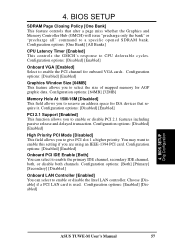
... 4. Configuration options: [Disabled] [Enabled] PCI 2.1 Support [Enabled] This function allows you are using an IEEE-1394 PCI card. BIOS SETUP Chip Configuration ASUS TUWE-M User's Manual 57 Choose [Disable] if a PCI LAN card is used. 4. Configuration options: [Disabled] [Enabled] Onboard VGA [Enabled] Select to CPU...cycles. You may want to enable this setting if you to a specific opened SDRAM bank. Configuration options: [64MB] [32MB] Memory Hole At 15M-16M [Disabled] This field allows you to reserve an address space for AGP graphic data. BIOS SETUP SDRAM Page ...
... 4. Configuration options: [Disabled] [Enabled] PCI 2.1 Support [Enabled] This function allows you are using an IEEE-1394 PCI card. BIOS SETUP Chip Configuration ASUS TUWE-M User's Manual 57 Choose [Disable] if a PCI LAN card is used. 4. Configuration options: [Disabled] [Enabled] Onboard VGA [Enabled] Select to CPU...cycles. You may want to enable this setting if you to a specific opened SDRAM bank. Configuration options: [64MB] [32MB] Memory Hole At 15M-16M [Disabled] This field allows you to reserve an address space for AGP graphic data. BIOS SETUP SDRAM Page ...
TUWE-M User Manual
Page 73
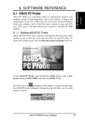
...PC Probe. ASUS TUWE-M User's Manual 73 To bypass this startup screen, clear the Show up in next execution check box. To start ASUS PC Probe, click the Windows Start button, point to see the status of your computer system's vital components, such as hard disk space, memory usage, ...and CPU type, CPU speed, and internal/external frequencies through the DMI Explorer. 6.1.1 Starting ASUS PC Probe When ASUS PC Probe starts, a splash screen appears allowing you to select whether or not to...
...PC Probe. ASUS TUWE-M User's Manual 73 To bypass this startup screen, clear the Show up in next execution check box. To start ASUS PC Probe, click the Windows Start button, point to see the status of your computer system's vital components, such as hard disk space, memory usage, ...and CPU type, CPU speed, and internal/external frequencies through the DMI Explorer. 6.1.1 Starting ASUS PC Probe When ASUS PC Probe starts, a splash screen appears allowing you to select whether or not to...
TUWE-M User Manual
Page 76
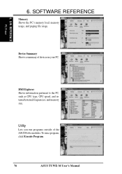
SOFTWARE REFERENCE Memory Shows the PC's memory load, memory usage, and paging file usage. Utility Lets you run a program, click Execute Program. 76 ASUS TUWE-M User's Manual DMI Explorer Shows information pertinent to the PC, such as CPU type, CPU speed, and internal/external frequencies, and memory size. S/W REFERENCE PC Probe 6. To run programs outside of devices in your PC. 6. Device Summary Shows a summary of the ASUS Probe modules.
SOFTWARE REFERENCE Memory Shows the PC's memory load, memory usage, and paging file usage. Utility Lets you run a program, click Execute Program. 76 ASUS TUWE-M User's Manual DMI Explorer Shows information pertinent to the PC, such as CPU type, CPU speed, and internal/external frequencies, and memory size. S/W REFERENCE PC Probe 6. To run programs outside of devices in your PC. 6. Device Summary Shows a summary of the ASUS Probe modules.


