User Guide
Page 11
ASUS TS150-E2 1-1 Product introduction Chapter 1 This chapter describes the general features of the barebone server, including sections on the front panel and rear panel specifications.
ASUS TS150-E2 1-1 Product introduction Chapter 1 This chapter describes the general features of the barebone server, including sections on the front panel and rear panel specifications.
User Guide
Page 12
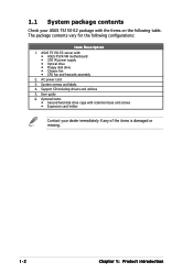
...; 300 W power supply • Optical drive • Floppy disk drive • Chassis fan • CPU fan and heatsink assembly 2. ASUS TS150-E2 server with retention base and screws • Expansion card holder Contact your ASUS TS150-E2 package with the items on the following configurations: Item Description 1. Support CD including drivers and utilities 5. AC power cord...
...; 300 W power supply • Optical drive • Floppy disk drive • Chassis fan • CPU fan and heatsink assembly 2. ASUS TS150-E2 server with retention base and screws • Expansion card holder Contact your ASUS TS150-E2 package with the items on the following configurations: Item Description 1. Support CD including drivers and utilities 5. AC power cord...
User Guide
Page 13
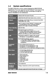
... Bus Memory LAN Storage Expansion slots Drive bays Rear panel Chassis fan Hardware monitors Power supply Pedestal with 24-pin ATX and 4-pin 12V plugs ASUS TS150-E2 1-3 x 9.6 in.) Northbridge: Intel® E7221 Memory Controller Hub (MCH) Southbridge: Intel® ICH6R LGA775 socket for Intel® Pentium® 4 processor with Extended Memory 64...
... Bus Memory LAN Storage Expansion slots Drive bays Rear panel Chassis fan Hardware monitors Power supply Pedestal with 24-pin ATX and 4-pin 12V plugs ASUS TS150-E2 1-3 x 9.6 in.) Northbridge: Intel® E7221 Memory Controller Hub (MCH) Southbridge: Intel® ICH6R LGA775 socket for Intel® Pentium® 4 processor with Extended Memory 64...
User Guide
Page 15
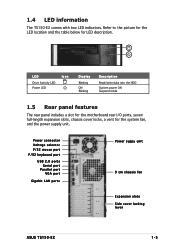
... USB 2.0 ports Serial port Parallel port VGA port Gigabit LAN ports Power suppy unit 9 cm chassis fan Expansion slots Side cover locking lever ASUS TS150-E2 1-5 1.4 LED information The TS150-E2 comes with two LED indicators. Refer to the picture for the LED location and the table below for the system fan, and the power...
... USB 2.0 ports Serial port Parallel port VGA port Gigabit LAN ports Power suppy unit 9 cm chassis fan Expansion slots Side cover locking lever ASUS TS150-E2 1-5 1.4 LED information The TS150-E2 comes with two LED indicators. Refer to the picture for the LED location and the table below for the system fan, and the power...
User Guide
Page 17
Chapter 2 This chapter lists the hardware setup procedures that you have to perform when installing or removing system components. Hardware setup ASUS TS150-E2 2-1
Chapter 2 This chapter lists the hardware setup procedures that you have to perform when installing or removing system components. Hardware setup ASUS TS150-E2 2-1
User Guide
Page 19
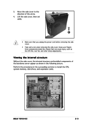
... from components inside the chassis that you unplug the power cord before removing the side cover. • Take extra care when removing the side cover. ASUS TS150-E2 2-3
... from components inside the chassis that you unplug the power cord before removing the side cover. • Take extra care when removing the side cover. ASUS TS150-E2 2-3
User Guide
Page 21
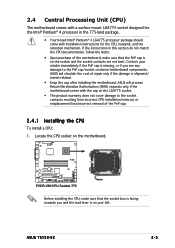
... Central Processing Unit (CPU) The motherboard comes with a surface mount LGA775 socket designed for the CPU, heatsink, and the retention mechanism. ASUS TS150-E2 2-5 P5CR-VM P5CR-VM CPU Socket 775 Before installing the CPU, make sure that the socket box is facing towards you see any damage... the CPU socket on the LGA775 socket. • The product warranty does not cover damage to the PnP cap/socket contacts/motherboard components. ASUS will shoulder the cost of the motherboard, make sure that the PnP cap is shipment/ transit-related. • Keep the cap after installing...
... Central Processing Unit (CPU) The motherboard comes with a surface mount LGA775 socket designed for the CPU, heatsink, and the retention mechanism. ASUS TS150-E2 2-5 P5CR-VM P5CR-VM CPU Socket 775 Before installing the CPU, make sure that the socket box is facing towards you see any damage... the CPU socket on the LGA775 socket. • The product warranty does not cover damage to the PnP cap/socket contacts/motherboard components. ASUS will shoulder the cost of the motherboard, make sure that the PnP cap is shipment/ transit-related. • Keep the cap after installing...
User Guide
Page 23
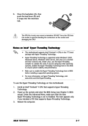
... Hyper-Threading Technology, visit www.intel.com/info/hyperthreading. Power up the system and enter the BIOS Setup (see Chapter 5: BIOS setup). Reboot the computer. ASUS TS150-E2 2-7 6. If you installed a CPU that supports Hyper-Threading Technology. 3. The item appears only if you are using any other operating systems, disable the Hyper-Threading...
... Hyper-Threading Technology, visit www.intel.com/info/hyperthreading. Power up the system and enter the BIOS Setup (see Chapter 5: BIOS setup). Reboot the computer. ASUS TS150-E2 2-7 6. If you installed a CPU that supports Hyper-Threading Technology. 3. The item appears only if you are using any other operating systems, disable the Hyper-Threading...
User Guide
Page 25
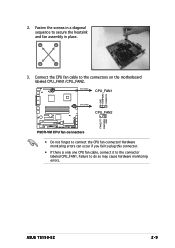
Connect the CPU fan cable to connect the CPU fan connector! ASUS TS150-E2 2-9 A B B A 3. CPU_FAN1 CPU_FAN1 GND FANPWR2 FANOUT4 CPU_FAN2 CPU_FAN2 FANOUT7 FANPWR3 GND P5CR-VM P5CR-VM CPU fan connectors • Do not forget to the connectors on ...
Connect the CPU fan cable to connect the CPU fan connector! ASUS TS150-E2 2-9 A B B A 3. CPU_FAN1 CPU_FAN1 GND FANPWR2 FANOUT4 CPU_FAN2 CPU_FAN2 FANOUT7 FANPWR3 GND P5CR-VM P5CR-VM CPU fan connectors • Do not forget to the connectors on ...
User Guide
Page 27
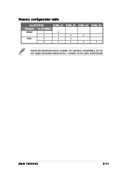
For optimum compatibility, do not mix single and double-sided memory modules on the same motherboard. Memory configuration table ALLOCATION Channel # of DIMMS SINGLE 1 3 DUAL 2 4 DIMM_A1 DIMM_B1 DIMM_A2 • • • • • • • • • DIMM_B2 • Install only identical memory modules. ASUS TS150-E2 2-11
For optimum compatibility, do not mix single and double-sided memory modules on the same motherboard. Memory configuration table ALLOCATION Channel # of DIMMS SINGLE 1 3 DUAL 2 4 DIMM_A1 DIMM_B1 DIMM_A2 • • • • • • • • • DIMM_B2 • Install only identical memory modules. ASUS TS150-E2 2-11
User Guide
Page 29
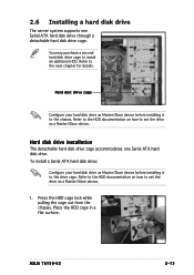
Hard disk drive cage Configure your hard disk drive as Master/Slave device before installing it to set the drive as a Master/Slave device. 1. ASUS TS150-E2 2-13 2.6 Installing a hard disk drive The server system supports one Serial ATA hard disk drive. Refer to the HDD documentation on how to the chassis. ...
Hard disk drive cage Configure your hard disk drive as Master/Slave device before installing it to set the drive as a Master/Slave device. 1. ASUS TS150-E2 2-13 2.6 Installing a hard disk drive The server system supports one Serial ATA hard disk drive. Refer to the HDD documentation on how to the chassis. ...
User Guide
Page 31
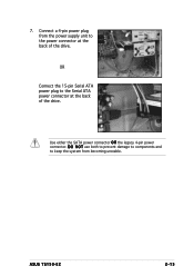
D O N O T use both to prevent damage to components and to the power connector at the back of the drive. Use either the SATA power connector O R the legacy 4-pin power connector. ASUS TS150-E2 2-15 7. Connect a 4-pin power plug from the power supply unit to keep the system from becoming unstable. OR Connect the 15-pin Serial ATA power plug to the Serial ATA power connector at the back of the drive.
D O N O T use both to prevent damage to components and to the power connector at the back of the drive. Use either the SATA power connector O R the legacy 4-pin power connector. ASUS TS150-E2 2-15 7. Connect a 4-pin power plug from the power supply unit to keep the system from becoming unstable. OR Connect the 15-pin Serial ATA power plug to the Serial ATA power connector at the back of the drive.
User Guide
Page 33
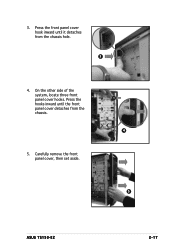
Carefully remove the front panel cover, then set aside. 5 ASUS TS150-E2 2-17 On the other side of the system, locate three front panel cover hooks. Press the front panel cover hook inward until the front panel cover detaches from the chassis hole. 3 4. 3. Press the hooks inward until it detaches from the chassis. 4 5.
Carefully remove the front panel cover, then set aside. 5 ASUS TS150-E2 2-17 On the other side of the system, locate three front panel cover hooks. Press the front panel cover hook inward until the front panel cover detaches from the chassis hole. 3 4. 3. Press the hooks inward until it detaches from the chassis. 4 5.
User Guide
Page 35
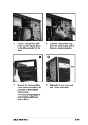
Connect a 4-pin power plug from the first optical drive) to the drive power connector. 7 8 7. ASUS TS150-E2 2-19 Connect a 40-pin IDE cable (from the power supply unit to the IDE connector on the drive. 6. Follow the same procedures when installing additional optical drives. 8. Remove the front panel bay cover opposite the drive bay you used by pressing the hooks inward. 5 6 5. Reinstall the front panel and side covers when done.
Connect a 4-pin power plug from the first optical drive) to the drive power connector. 7 8 7. ASUS TS150-E2 2-19 Connect a 40-pin IDE cable (from the power supply unit to the IDE connector on the drive. 6. Follow the same procedures when installing additional optical drives. 8. Remove the front panel bay cover opposite the drive bay you used by pressing the hooks inward. 5 6 5. Reinstall the front panel and side covers when done.
User Guide
Page 37
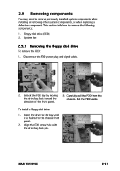
... bay lock pin. 2.9 Removing components You may need to the chassis front panel. 2. Floppy disk drive (FDD) 2. Disconnect the FDD power plug and signal cable. 2 3 2. ASUS TS150-E2 2-21 Unlock the FDD bay by moving the drive bay lock toward the direction of the front panel. 3. Insert the drive to the bay until...
... bay lock pin. 2.9 Removing components You may need to the chassis front panel. 2. Floppy disk drive (FDD) 2. Disconnect the FDD power plug and signal cable. 2 3 2. ASUS TS150-E2 2-21 Unlock the FDD bay by moving the drive bay lock toward the direction of the front panel. 3. Insert the drive to the bay until...
User Guide
Page 39
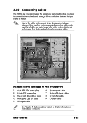
... 1. 4-pin ATX 12V power plug 2. 24-pin ATX power plug 3. IDE signal cable 6. System fan cables 9. System panel cable 7. ASUS TS150-E2 2-23 Floppy disk drive ribbon cable 4. When installing system devices and connecting cables, make sure that you need to connect to the motherboard, ...cables are routed properly for the chassis kit are already connected upon shipment. Front panel USB 2.0 cable 5. 2.10 Connecting cables The TS150-E2 chassis includes the power and signal cables that you intend to install. Serial ATA signal cables 8. CPU fan cables See "Chapter 4: ...
... 1. 4-pin ATX 12V power plug 2. 24-pin ATX power plug 3. IDE signal cable 6. System fan cables 9. System panel cable 7. ASUS TS150-E2 2-23 Floppy disk drive ribbon cable 4. When installing system devices and connecting cables, make sure that you need to connect to the motherboard, ...cables are routed properly for the chassis kit are already connected upon shipment. Front panel USB 2.0 cable 5. 2.10 Connecting cables The TS150-E2 chassis includes the power and signal cables that you intend to install. Serial ATA signal cables 8. CPU fan cables See "Chapter 4: ...
User Guide
Page 41
ASUS TS150-E2 3-1 Installation options Chapter 3 This chapter describes how to install optional components into the barebone server.
ASUS TS150-E2 3-1 Installation options Chapter 3 This chapter describes how to install optional components into the barebone server.
User Guide
Page 43
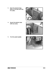
Turn the system upright. ASUS TS150-E2 3-3 3. Secure the retention base with two screws. 5. Insert the retention base hooks to the holes until they fit in place. 4.
Turn the system upright. ASUS TS150-E2 3-3 3. Secure the retention base with two screws. 5. Insert the retention base hooks to the holes until they fit in place. 4.
User Guide
Page 45
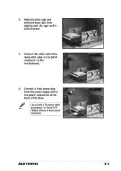
Align the drive cage and retention base rails, then slightly push the cage until it clicks in place. 5. Connect the other end of the drive. ASUS TS150-E2 3-5 4. Connect a 4-pin power plug from the power supply unit to the power connectors at the back of the Serial ATA cable to the SATA connector on the motherboard. 6. Use a Serial ATA power cable and adapter for Serial ATA HDD(s) without a 4-pin power connector.
Align the drive cage and retention base rails, then slightly push the cage until it clicks in place. 5. Connect the other end of the drive. ASUS TS150-E2 3-5 4. Connect a 4-pin power plug from the power supply unit to the power connectors at the back of the Serial ATA cable to the SATA connector on the motherboard. 6. Use a Serial ATA power cable and adapter for Serial ATA HDD(s) without a 4-pin power connector.
User Guide
Page 47
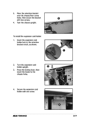
Secure the expansion card holder with two screws. 4. Place the retention bracket over the chassis floor screw holes, then secure the bracket with one screw. Insert the expansion card holder lock to the chassis holes. 2 4. Press the locking lever, then insert the hooks to the retention bracket notch, as shown. 3 1 2. To install the expansion card holder: 1. Turn the chassis upright. ASUS TS150-E2 4 3-7 3. Turn the expansion card holder upright. 3 3.
Secure the expansion card holder with two screws. 4. Place the retention bracket over the chassis floor screw holes, then secure the bracket with one screw. Insert the expansion card holder lock to the chassis holes. 2 4. Press the locking lever, then insert the hooks to the retention bracket notch, as shown. 3 1 2. To install the expansion card holder: 1. Turn the chassis upright. ASUS TS150-E2 4 3-7 3. Turn the expansion card holder upright. 3 3.


