
User Guide
Page 3
...panel (internal 1-5 1.4 Rear panel 1-7 1.5 Internal components 1-9 1.6 LED panel 1-10 Chapter 2: Basic Installation 2.1 Preparation 2-2 2.2 Before you proceed 2-2 2.3 Removing the cover 2-3 2.4 Removing the power supply 2-4 2.5 Installing a CPU 2-5 2.5.1 Removing the CPU fan and heatsink assembly ....... 2-5 2.5.2 CPU installation 2-6 2.5.3 Reinstalling the CPU fan and heatsink assembly ..... 2-9 2.6 Installing a DIMM 2-10 ...Installing a floppy disk drive 2-19 2.10 Installing a hard disk drive (HDD 2-20 2.11 Reinstalling the power supply unit 2-23 2.12 Replacing the cover 2-25 iii
...panel (internal 1-5 1.4 Rear panel 1-7 1.5 Internal components 1-9 1.6 LED panel 1-10 Chapter 2: Basic Installation 2.1 Preparation 2-2 2.2 Before you proceed 2-2 2.3 Removing the cover 2-3 2.4 Removing the power supply 2-4 2.5 Installing a CPU 2-5 2.5.1 Removing the CPU fan and heatsink assembly ....... 2-5 2.5.2 CPU installation 2-6 2.5.3 Reinstalling the CPU fan and heatsink assembly ..... 2-9 2.6 Installing a DIMM 2-10 ...Installing a floppy disk drive 2-19 2.10 Installing a hard disk drive (HDD 2-20 2.11 Reinstalling the power supply unit 2-23 2.12 Replacing the cover 2-25 iii
User Guide
Page 7
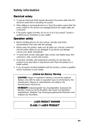
... or your retailer. Replace only with the package. • Before using the product, make sure all the documentation that the power cables for the devices are unplugged before relocating the system. • When adding or removing devices to or from connectors, slots...not damaged. Operation safety • Before installing devices into the system, carefully read all cables are correctly connected and the power cables are connected. • If the power supply is incorrectly replaced. Lithium-Ion Battery Warning C A U T I C H T: Explosionsgetahr bei unsachgemäßen ...
... or your retailer. Replace only with the package. • Before using the product, make sure all the documentation that the power cables for the devices are unplugged before relocating the system. • When adding or removing devices to or from connectors, slots...not damaged. Operation safety • Before installing devices into the system, carefully read all cables are correctly connected and the power cables are connected. • If the power supply is incorrectly replaced. Lithium-Ion Battery Warning C A U T I C H T: Explosionsgetahr bei unsachgemäßen ...
User Guide
Page 8
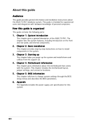
...through the BIOS Setup menus and describes the BIOS parameters. 6. Chapter 4: Motherboard information This chapter gives information about the ASUS T2-PH1 barebone system. This guide is organized This guide contains the following parts: 1. How this guide is intended for this ... that comes with hardware knowledge of the ASUS T2-PH1. Chapter 2: Basic installation This chapter provides step-by-step instructions on the front and rear panel, and internal components. 2. Appendix The Appendix includes the power supply unit specification for experienced users and integrators ...
...through the BIOS Setup menus and describes the BIOS parameters. 6. Chapter 4: Motherboard information This chapter gives information about the ASUS T2-PH1 barebone system. This guide is organized This guide contains the following parts: 1. How this guide is intended for this ... that comes with hardware knowledge of the ASUS T2-PH1. Chapter 2: Basic installation This chapter provides step-by-step instructions on the front and rear panel, and internal components. 2. Appendix The Appendix includes the power supply unit specification for experienced users and integrators ...
User Guide
Page 10
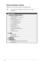
...ROM/CD-RW/DVD-ROM/DVD-RW) • Floppy disk drive x Cables • AC power cable • Serial ATA cable • Serial ATA power cable 3 . P H 1 b a r e b o n e s y s t e m with • ASUS motherboard • 250 W PFC/non-PFC power supply unit • Gigabit LAN port • CPU fan and heatsink assembly • 2 x ...8226; LED panel • Audio DJ play buttons 2 . User guide 5 . Support CD 4 . System package contents Check your T2-PH1 system package for the following items. If any of the items is damaged or missing, contact your retailer immediately. Item description 1 .
...ROM/CD-RW/DVD-ROM/DVD-RW) • Floppy disk drive x Cables • AC power cable • Serial ATA cable • Serial ATA power cable 3 . P H 1 b a r e b o n e s y s t e m with • ASUS motherboard • 250 W PFC/non-PFC power supply unit • Gigabit LAN port • CPU fan and heatsink assembly • 2 x ...8226; LED panel • Audio DJ play buttons 2 . User guide 5 . Support CD 4 . System package contents Check your T2-PH1 system package for the following items. If any of the items is damaged or missing, contact your retailer immediately. Item description 1 .
User Guide
Page 18
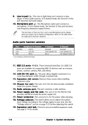
...introduction This port allows Gigabit connection to the table below for the PSU fan that provides ventilation inside the power supply unit. 1 7 . 9 . This vent is for the fan that provides ventilation inside the system ... In * Low Frequency Enhanced Output 4-Channel Surround Front Speaker Out Mic In 6-Channel Surround Front Speaker Out LFE Output*/Center 1 1 . This connector is for the power cable and plug. 1 8 . E x p a n s i o n c a r d l o c k . L A N ( R J - 4 5 ) p o r t . In 4/6-channel mode, the function of this switch. 1 9 . L i n e I n p o r ...
...introduction This port allows Gigabit connection to the table below for the PSU fan that provides ventilation inside the power supply unit. 1 7 . 9 . This vent is for the fan that provides ventilation inside the system ... In * Low Frequency Enhanced Output 4-Channel Surround Front Speaker Out Mic In 6-Channel Surround Front Speaker Out LFE Output*/Center 1 1 . This connector is for the power cable and plug. 1 8 . E x p a n s i o n c a r d l o c k . L A N ( R J - 4 5 ) p o r t . In 4/6-channel mode, the function of this switch. 1 9 . L i n e I n p o r ...
User Guide
Page 19
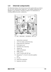
...Floppy disk drive (optional) 4. ASUS motherboard 8. Serial ATA connectors 13. 1.5 Internal components The illustration below is the internal view of the system when you remove the top cover and the power supply unit. The installed components are ...labeled for instructions on installing additional system components. 1 6 3 2 9 8 7 4 5 10 13 11 12 1. Front panel cover 5. Hard disk drive metal tray 6. Optical drive (optional) 2. 5.25-inch empty optical drive bay 3. DIMM sockets 9. PCI slot 12. Expansion card slots ASUS T2-PH1...
...Floppy disk drive (optional) 4. ASUS motherboard 8. Serial ATA connectors 13. 1.5 Internal components The illustration below is the internal view of the system when you remove the top cover and the power supply unit. The installed components are ...labeled for instructions on installing additional system components. 1 6 3 2 9 8 7 4 5 10 13 11 12 1. Front panel cover 5. Hard disk drive metal tray 6. Optical drive (optional) 2. 5.25-inch empty optical drive bay 3. DIMM sockets 9. PCI slot 12. Expansion card slots ASUS T2-PH1...
User Guide
Page 22
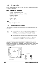
...to install 1. Central processing unit (CPU) 2. DDR Dual Inline Memory Module (DIMM) 3. 2.1 Preparation Before you proceed, make sure that the standby power LED is ON, in sleep mode or in the system. Floppy disk drive Tool Phillips (cross) screw driver 2.2 Before you proceed Take note of...components into the system. • Use a grounded wrist strap or touch a safely grounded object or a metal object, such as the power supply case, before installing any component, place it on them. • Whenever you uninstall any system component. ® Onboard LED 2-2 SB_PWR ON Standby...
...to install 1. Central processing unit (CPU) 2. DDR Dual Inline Memory Module (DIMM) 3. 2.1 Preparation Before you proceed, make sure that the standby power LED is ON, in sleep mode or in the system. Floppy disk drive Tool Phillips (cross) screw driver 2.2 Before you proceed Take note of...components into the system. • Use a grounded wrist strap or touch a safely grounded object or a metal object, such as the power supply case, before installing any component, place it on them. • Whenever you uninstall any system component. ® Onboard LED 2-2 SB_PWR ON Standby...
User Guide
Page 24
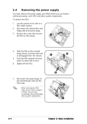
.... 3. Slide the PSU as the zoomed image shows, until the side hook 4 6 is disengaged from the chassis. 5. 2.4 Removing the power supply You must remove the power supply unit (PSU) before you can install a central processing unit( CPU) and other system components. 5 7 7 7 2-4 Chapter 2: Basic installation Remove the screw that secures 3 the PSU to ...
.... 3. Slide the PSU as the zoomed image shows, until the side hook 4 6 is disengaged from the chassis. 5. 2.4 Removing the power supply You must remove the power supply unit (PSU) before you can install a central processing unit( CPU) and other system components. 5 7 7 7 2-4 Chapter 2: Basic installation Remove the screw that secures 3 the PSU to ...
User Guide
Page 33
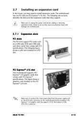
... for the location of the ATX12V2 connector. Make sure to connect the 4-pin power plug from the power supply unit to the ATX12V2 connector on a PCI slot. ASUS T2-PH1 2-13 Failure to do so may cause you may need to unplug the power cord before installing a PCI Express™ x16 graphic card. 2.7 Installing an expansion card...
... for the location of the ATX12V2 connector. Make sure to connect the 4-pin power plug from the power supply unit to the ATX12V2 connector on a PCI slot. ASUS T2-PH1 2-13 Failure to do so may cause you may need to unplug the power cord before installing a PCI Express™ x16 graphic card. 2.7 Installing an expansion card...
User Guide
Page 37
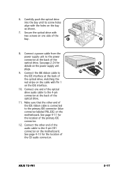
...2-24 for details on the bay as shown. 7. See page 4-11 for the location of the primary IDE connector. 12. Connect a power cable from the power supply unit to the 4-pin connector at the back of the optical drive. Secure the optical drive with Pin 1 on one end of the ...Carefully push the optical drive into the bay until its screw holes align with the holes on the power supply unit plugs. 10 9. 6. See page 4-13 for the location of the CD audio connector. 7 8 9 ASUS T2-PH1 2-17 Connect the other end of the audio cable to the primary IDE connector (blue connector labeled ...
...2-24 for details on the bay as shown. 7. See page 4-11 for the location of the primary IDE connector. 12. Connect a power cable from the power supply unit to the 4-pin connector at the back of the optical drive. Secure the optical drive with Pin 1 on one end of the ...Carefully push the optical drive into the bay until its screw holes align with the holes on the power supply unit plugs. 10 9. 6. See page 4-13 for the location of the CD audio connector. 7 8 9 ASUS T2-PH1 2-17 Connect the other end of the audio cable to the primary IDE connector (blue connector labeled ...
User Guide
Page 39
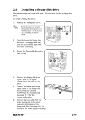
... the front panel cover. Connect a power cable from the power supply unit to the signal connector at the back of section "2.8 Installing an optical drive." 2 2. For instructions on the motherboard. Connect the floppy disk drive signal cable to the power connector at the back of the drive... the power supply unit plugs. See page 2-24 for details on the bay. 3. To install a floppy disk drive: 1. See page 4-13 for a floppy disk drive. Carefully insert the floppy disk drive into the floppy drive bay until the screw holes align with two screws. 33 4. ASUS T2-PH1 6 ...
... the front panel cover. Connect a power cable from the power supply unit to the signal connector at the back of section "2.8 Installing an optical drive." 2 2. For instructions on the motherboard. Connect the floppy disk drive signal cable to the power connector at the back of the drive... the power supply unit plugs. See page 2-24 for details on the bay. 3. To install a floppy disk drive: 1. See page 4-13 for a floppy disk drive. Carefully insert the floppy disk drive into the floppy drive bay until the screw holes align with two screws. 33 4. ASUS T2-PH1 6 ...
User Guide
Page 41
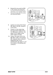
Connect a 4-pin power plug from the power supply unit to the chassis hooks. 7. ASUS T2-PH1 2-21 See page 4-11 for details on the power supply unit plugs. 9 10. Reinstall the tray and the HDD to the chassis by locking the tray slots to the HDD power connector. See 8 page 2-24 for the location of the primary IDE connector. Connect...
Connect a 4-pin power plug from the power supply unit to the chassis hooks. 7. ASUS T2-PH1 2-21 See page 4-11 for details on the power supply unit plugs. 9 10. Reinstall the tray and the HDD to the chassis by locking the tray slots to the HDD power connector. See 8 page 2-24 for the location of the primary IDE connector. Connect...
User Guide
Page 42
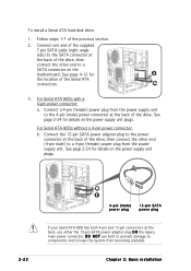
...right angle side) to the SATA connector at the back of the drive, then connect the other end (4-pin male) to a 4-pin (female) power plug from the power supply unit to keep the system from becoming unstable. See page 2-24 for details on the motherboard. See page 2-24 for 2 the location of the... drive. See page 4-12 for details on the power supply unit plugs. 2-22 3b 2 4-pin (male) power plug 15-pin SATA power plug If your Serial ATA HDD has both 4-pin and 15-pin connectors at the back, use both to prevent...
...right angle side) to the SATA connector at the back of the drive, then connect the other end (4-pin male) to a 4-pin (female) power plug from the power supply unit to keep the system from becoming unstable. See page 2-24 for details on the motherboard. See page 2-24 for 2 the location of the... drive. See page 4-12 for details on the power supply unit plugs. 2-22 3b 2 4-pin (male) power plug 15-pin SATA power plug If your Serial ATA HDD has both 4-pin and 15-pin connectors at the back, use both to prevent...
User Guide
Page 43
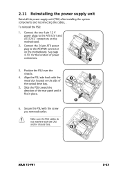
To reinstall the PSU: 1. Position the PSU over the chassis. 4. Connect the two 4-pin 12 V power plugs to the ATXPWR connector on the motherboard. Slide the PSU toward the direction of power connectors. 2 1 1 3. 2.11 Reinstalling the power supply unit Reinstall the power supply unit (PSU) after installing the system components and reconnecting the cables, . Connect the 24... location of the rear panel until it fits in place. 5 6. Make sure the PSU cables do not interfere with the CPU and/or chassis fans. 6 ASUS T2-PH1 2-23
To reinstall the PSU: 1. Position the PSU over the chassis. 4. Connect the two 4-pin 12 V power plugs to the ATXPWR connector on the motherboard. Slide the PSU toward the direction of power connectors. 2 1 1 3. 2.11 Reinstalling the power supply unit Reinstall the power supply unit (PSU) after installing the system components and reconnecting the cables, . Connect the 24... location of the rear panel until it fits in place. 5 6. Make sure the PSU cables do not interfere with the CPU and/or chassis fans. 6 ASUS T2-PH1 2-23
User Guide
Page 44
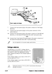
...selector The PSU has a 115 V/230 V voltage selector switch located beside the power connector. If the voltage supply in your area. Power supply unit plugs 8 9B 9A 7 1 1 2 7. Connect the 4-pin power plug(s) to the power connector of the optical drive(s). 9A. or - 9B. Use this switch ... voltage according to 115 V. If the voltage supply in a 230 V environment will seriously damage the system! Connect the 4-pin power plug to the power connector of the floppy disk drive. 8. See the Appendix for the power supply specifications. Chapter 2: Basic installation Connect the 15...
...selector The PSU has a 115 V/230 V voltage selector switch located beside the power connector. If the voltage supply in your area. Power supply unit plugs 8 9B 9A 7 1 1 2 7. Connect the 4-pin power plug(s) to the power connector of the optical drive(s). 9A. or - 9B. Use this switch ... voltage according to 115 V. If the voltage supply in a 230 V environment will seriously damage the system! Connect the 4-pin power plug to the power connector of the floppy disk drive. 8. See the Appendix for the power supply specifications. Chapter 2: Basic installation Connect the 15...
User Guide
Page 62
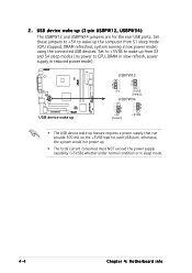
... up (3-pin USBPW12, USBPW34) The USBPW12 and USBPW34 jumpers are for each USB port; Set these jumpers to +5V to CPU, DRAM in slow refresh, power supply in sleep mode. 4-4 Chapter 4: Motherboard info USB device wake-up from S1 sleep mode (CPU stopped, DRAM refreshed, system running in low... up ® USBPW12 2 1 +5V 3 2 +5VSB (Default) USBPW34 2 1 +5V (Default) 3 2 +5VSB • The USB device wake-up the computer from S3 and S4 sleep modes (no power to wake up feature requires a power supply that can provide 500 mA on the +5VSB lead for the rear USB ports.
... up (3-pin USBPW12, USBPW34) The USBPW12 and USBPW34 jumpers are for each USB port; Set these jumpers to +5V to CPU, DRAM in slow refresh, power supply in sleep mode. 4-4 Chapter 4: Motherboard info USB device wake-up from S1 sleep mode (CPU stopped, DRAM refreshed, system running in low... up ® USBPW12 2 1 +5V 3 2 +5VSB (Default) USBPW34 2 1 +5V (Default) 3 2 +5VSB • The USB device wake-up the computer from S3 and S4 sleep modes (no power to wake up feature requires a power supply that can provide 500 mA on the +5VSB lead for the rear USB ports.
User Guide
Page 68
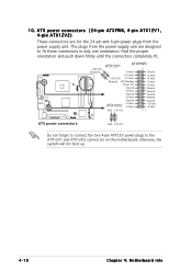
... (24-pin ATXPWR, 4-pin ATX12V1, 4-pin ATX12V2) These connectors are for the 24-pin and 4-pin power plugs from the power supply unit are designed to the ATX12V1 and ATX12V2 connectors on the motherboard; Find the proper orientation and push down firmly until the connectors ...-5 Volts Ground Ground Ground PSON# Ground -12 Volts +3 Volts 1 ATX power connectors GND +12V DC Do not forget to connect the two 4-pin ATX12V power plugs to fit these connectors in only one orientation. 10. The plugs from the power supply unit. otherwise, the system will not boot up. 4-10 Chapter 4: Motherboard ...
... (24-pin ATXPWR, 4-pin ATX12V1, 4-pin ATX12V2) These connectors are for the 24-pin and 4-pin power plugs from the power supply unit are designed to the ATX12V1 and ATX12V2 connectors on the motherboard; Find the proper orientation and push down firmly until the connectors ...-5 Volts Ground Ground Ground PSON# Ground -12 Volts +3 Volts 1 ATX power connectors GND +12V DC Do not forget to connect the two 4-pin ATX12V power plugs to fit these connectors in only one orientation. 10. The plugs from the power supply unit. otherwise, the system will not boot up. 4-10 Chapter 4: Motherboard ...
User Guide
Page 72
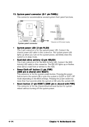
...This connector is for the system power button. System panel connector (8-1 pin PANEL) This connector accommodates several system front panel functions. ® PWR+ GND RESET PWR PANEL PLED+ PLEDHDLED+ HDLED- 15. System panel connector PLED HDLED * Requires an ATX power supply. • System power LED (2-pin PLED) This 2-...pin connector is for the chassis-mounted reset button for the system power LED.
...This connector is for the system power button. System panel connector (8-1 pin PANEL) This connector accommodates several system front panel functions. ® PWR+ GND RESET PWR PANEL PLED+ PLEDHDLED+ HDLED- 15. System panel connector PLED HDLED * Requires an ATX power supply. • System power LED (2-pin PLED) This 2-...pin connector is for the chassis-mounted reset button for the system power LED.
User Guide
Page 102
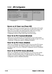
...an ATX power supply that provides at least 1A on state, whatever the system state was before the AC power loss. Configuration options: [Disabled] [Enabled] Power On By PCI/PCIE Devices [Disabled] When set to Power Off, ...Power Loss Power On By PS/2 Keyboard Power On By PS/2 Mouse Power On By PCI/PCIE Devices Power On By External Modems Power On By RTC Alarm [Power Off] [Disabled] [Disabled] [Disabled] [Disabled] [Disabled] Go into either off state after an AC power loss. Configuration options: [Disabled] [Enabled] 5-30 Chapter 5: BIOS setup This feature requires an ATX power supply...
...an ATX power supply that provides at least 1A on state, whatever the system state was before the AC power loss. Configuration options: [Disabled] [Enabled] Power On By PCI/PCIE Devices [Disabled] When set to Power Off, ...Power Loss Power On By PS/2 Keyboard Power On By PS/2 Mouse Power On By PCI/PCIE Devices Power On By External Modems Power On By RTC Alarm [Power Off] [Disabled] [Disabled] [Disabled] [Disabled] [Disabled] Go into either off state after an AC power loss. Configuration options: [Disabled] [Enabled] 5-30 Chapter 5: BIOS setup This feature requires an ATX power supply...
User Guide
Page 111
Appendix The Appendix includes the power supply unit specification for this system. MODE ASUS T2-PH1 Appendix
Appendix The Appendix includes the power supply unit specification for this system. MODE ASUS T2-PH1 Appendix


