User Guide
Page 8
... install drivers and utilities from the support CD. 4 . Chapter 2: Basic installation This chapter provides step-by-step instructions on the front and rear panel, and internal components. 2. Appendix The Appendix includes the power supply unit specification for experienced users and integrators with the system. This guide is intended for this guide is organized This guide contains the following parts: 1. How this system. This chapter includes the motherboard layout, jumper settings, and connector locations...
... install drivers and utilities from the support CD. 4 . Chapter 2: Basic installation This chapter provides step-by-step instructions on the front and rear panel, and internal components. 2. Appendix The Appendix includes the power supply unit specification for experienced users and integrators with the system. This guide is intended for this guide is organized This guide contains the following parts: 1. How this system. This chapter includes the motherboard layout, jumper settings, and connector locations...
User Guide
Page 10
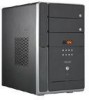
.... User guide 5 . P H 1 b a r e b o n e s y s t e m with • ASUS motherboard • 250 W PFC/non-PFC power supply unit • Gigabit LAN port • CPU fan and heatsink assembly • 2 x 5.25" drive bays • 1 x 3.5" floppy disk drive bay • 1 x 3.5" hard disk drive bay • 6 x USB 2.0 ports • 2 x IEEE 1394a ports • S/PDIF out port • 7-in-1 storage card reader • FM radio module and radio antenna • LED panel • Audio DJ play buttons 2 . Item description 1 . Support CD 4 . Optional items • Optical drive (CD-ROM/CD...
.... User guide 5 . P H 1 b a r e b o n e s y s t e m with • ASUS motherboard • 250 W PFC/non-PFC power supply unit • Gigabit LAN port • CPU fan and heatsink assembly • 2 x 5.25" drive bays • 1 x 3.5" floppy disk drive bay • 1 x 3.5" hard disk drive bay • 6 x USB 2.0 ports • 2 x IEEE 1394a ports • S/PDIF out port • 7-in-1 storage card reader • FM radio module and radio antenna • LED panel • Audio DJ play buttons 2 . Item description 1 . Support CD 4 . Optional items • Optical drive (CD-ROM/CD...
User Guide
Page 12
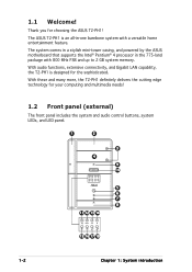
... a stylish mini-tower casing, and powered by the ASUS motherboard that supports the Intel® Pentium® 4 processor in -one barebone system with 800 MHz FSB and up to 2 GB system memory. The ASUS T2-PH1 is designed for your computing and multimedia needs! 1.2 Front panel (external) The front panel includes the system and audio control buttons, system LEDs, and LED panel. 1 2 3 4 9 10 MODE 5 6 7 8 11 12 13 14 MODE 15 16 17...
... a stylish mini-tower casing, and powered by the ASUS motherboard that supports the Intel® Pentium® 4 processor in -one barebone system with 800 MHz FSB and up to 2 GB system memory. The ASUS T2-PH1 is designed for your computing and multimedia needs! 1.2 Front panel (external) The front panel includes the system and audio control buttons, system LEDs, and LED panel. 1 2 3 4 9 10 MODE 5 6 7 8 11 12 13 14 MODE 15 16 17...
User Guide
Page 17
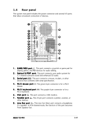
... port connects a VGA monitor. 7 . P a r a l l e l p o r t . In 4/6-channel mode, the function of devices. 1 14 2 3 4 15 5 6 7 16 8 9 10 17 11 18 12 13 19 1 . O p t i c a l S / P D I /O ports that conforms with serial specification. 4 . This port connects a mouse, modem, or other devices. 8 . 1.4 Rear panel The system rear panel includes the power connector and several I F p o r t . This port connects a joystick or game pad for playing games, and MIDI devices for 5.1-channel surround sound and enhanced 3D audio. 3 . This port connects your audio system for audio...
... port connects a VGA monitor. 7 . P a r a l l e l p o r t . In 4/6-channel mode, the function of devices. 1 14 2 3 4 15 5 6 7 16 8 9 10 17 11 18 12 13 19 1 . O p t i c a l S / P D I /O ports that conforms with serial specification. 4 . This port connects a mouse, modem, or other devices. 8 . 1.4 Rear panel The system rear panel includes the power connector and several I F p o r t . This port connects a joystick or game pad for playing games, and MIDI devices for 5.1-channel surround sound and enhanced 3D audio. 3 . This port connects your audio system for audio...
User Guide
Page 18
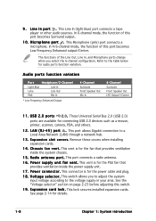
... 6-Channel Surround Front Speaker Out LFE Output*/Center 1 1 . This port allows Gigabit connection to the voltage supply in your area. This connector is for the power cable and plug. 1 8 . This switch allows you select the 6-channel configuration. See page 2-14 for audio ports function variation. M i c r o p h o n e p o r t . L A N ( R J - 4 5 ) p o r t . Remove these covers when installing expansion cards. 1 4 . R a d i o a n t e n n a p o r t . P o w e r c o n n e c t o r . E x p a n s i o n s l o t c o v e r s. In 4/6-channel mode, the function of...
... 6-Channel Surround Front Speaker Out LFE Output*/Center 1 1 . This port allows Gigabit connection to the voltage supply in your area. This connector is for the power cable and plug. 1 8 . This switch allows you select the 6-channel configuration. See page 2-14 for audio ports function variation. M i c r o p h o n e p o r t . L A N ( R J - 4 5 ) p o r t . Remove these covers when installing expansion cards. 1 4 . R a d i o a n t e n n a p o r t . P o w e r c o n n e c t o r . E x p a n s i o n s l o t c o v e r s. In 4/6-channel mode, the function of...
User Guide
Page 31
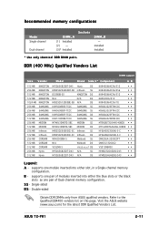
... Dual-channel memory configuration. S S - Refer to the Qualified DDR400 vendors list on this page. ASUS T2-PH1 2-11 supports one pair of modules inserted into either slot, in a Single-channel memory configuration. Single-sided D S - DDR (400 MHz) Qualified Vendors List DIMM support Size Vendor Model Brand Side/s* Component AB 512 MB 256 MB 512 MB 512 MB 1024 MB 256 MB 256 MB 256 MB 512 MB 256 MB 512 MB 256 MB 512 MB 256 MB 512 MB...
... Dual-channel memory configuration. S S - Refer to the Qualified DDR400 vendors list on this page. ASUS T2-PH1 2-11 supports one pair of modules inserted into either slot, in a Single-channel memory configuration. Single-sided D S - DDR (400 MHz) Qualified Vendors List DIMM support Size Vendor Model Brand Side/s* Component AB 512 MB 256 MB 512 MB 512 MB 1024 MB 256 MB 256 MB 256 MB 512 MB 256 MB 512 MB 256 MB 512 MB 256 MB 512 MB...
User Guide
Page 33
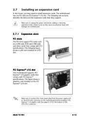
... connector. ASUS T2-PH1 2-13 The following figure shows a LAN card installed on a PCI slot. PCI Express™ x16 slot This motherboard supports PCI Express™ x16 graphic cards that comply with PCI specifications. Make sure to unplug the power cord before installing a PCI Express™ x16 graphic card. Failure to do so may need to the ATX12V2 connector on the PCI Express™ x16 slot. The figure shows a graphics card installed on the motherboard before adding or removing expansion cards. Make sure to connect the 4-pin power plug from the power supply...
... connector. ASUS T2-PH1 2-13 The following figure shows a LAN card installed on a PCI slot. PCI Express™ x16 slot This motherboard supports PCI Express™ x16 graphic cards that comply with PCI specifications. Make sure to unplug the power cord before installing a PCI Express™ x16 graphic card. Failure to do so may need to the ATX12V2 connector on the PCI Express™ x16 slot. The figure shows a graphics card installed on the motherboard before adding or removing expansion cards. Make sure to connect the 4-pin power plug from the power supply...
User Guide
Page 35
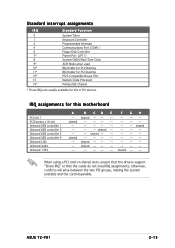
... -- -- -- -- -- ASUS T2-PH1 2-15 shared -- -- -- Standard interrupt assignments IRQ Standard Function 0 System Timer 1 Keyboard Controller 2 Programmable Interrupt 4 Communications Port (COM1) 6 Floppy Disk Controller 7* Printer Port (LPT1) 8 System CMOS/Real Time Clock 9* ACPI Mode when used 10* IRQ Holder for PCI Steering 11* IRQ Holder for PCI Steering 12* PS/2 Compatible Mouse Port 13 Numeric Data Processor 14* Primary IDE Channel * These IRQs are usually available for this motherboard PCI slot 1 PCI...
... -- -- -- -- -- ASUS T2-PH1 2-15 shared -- -- -- Standard interrupt assignments IRQ Standard Function 0 System Timer 1 Keyboard Controller 2 Programmable Interrupt 4 Communications Port (COM1) 6 Floppy Disk Controller 7* Printer Port (LPT1) 8 System CMOS/Real Time Clock 9* ACPI Mode when used 10* IRQ Holder for PCI Steering 11* IRQ Holder for PCI Steering 12* PS/2 Compatible Mouse Port 13 Numeric Data Processor 14* Primary IDE Channel * These IRQs are usually available for this motherboard PCI slot 1 PCI...
User Guide
Page 36
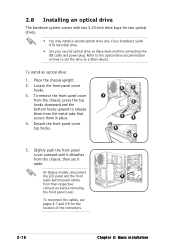
... front panel cover top hooks. 3 3 1 2 3 3 4 4 5. On Deluxe models, disconnect the LED panel and the front 5 audio button panel cables from the metal tabs that secure them from their respective connectors before connecting the IDE cable and power plug. To reconnect the cables, see pages 4-7 and 4-8 for two optical drives. • You may install a second optical drive only if you installed a Serial ATA hard disk drive. • Set your second optical drive as a Slave device. Locate the front panel cover hooks. 3. 2.8 Installing an optical drive The...
... front panel cover top hooks. 3 3 1 2 3 3 4 4 5. On Deluxe models, disconnect the LED panel and the front 5 audio button panel cables from the metal tabs that secure them from their respective connectors before connecting the IDE cable and power plug. To reconnect the cables, see pages 4-7 and 4-8 for two optical drives. • You may install a second optical drive only if you installed a Serial ATA hard disk drive. • Set your second optical drive as a Slave device. Locate the front panel cover hooks. 3. 2.8 Installing an optical drive The...
User Guide
Page 40
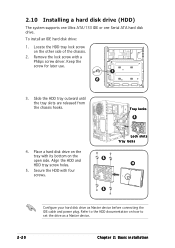
... a Philips screw driver. 2.10 Installing a hard disk drive (HDD) The system supports one Ultra ATA/133 IDE or one Serial ATA hard disk drive. Place a hard disk drive on the open side. Secure the HDD with four screws. To install an IDE hard disk drive: 1. Keep the screw for later use. 1 2 3. Locate the HDD tray lock screw on how to set the drive as Master device before connecting the IDE cable and power plug. Refer to the HDD documentation on the...
... a Philips screw driver. 2.10 Installing a hard disk drive (HDD) The system supports one Ultra ATA/133 IDE or one Serial ATA hard disk drive. Place a hard disk drive on the open side. Secure the HDD with four screws. To install an IDE hard disk drive: 1. Keep the screw for later use. 1 2 3. Locate the HDD tray lock screw on how to set the drive as Master device before connecting the IDE cable and power plug. Refer to the HDD documentation on the...
User Guide
Page 48
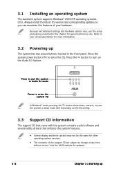
... Audio DJ mode MODE Press to enter the system OS In Windows® mode, pressing the button shuts down, restarts, or puts the system in sleep mode (S3) depending on the Audio DJ feature. Visit the ASUS website for general reference only. Because motherboard settings and hardware options vary, use the setup procedures presented in the front panel. Press the system power button ( ) to your hardware. 3.1 Installing an operating system The barebone system supports Windows...
... Audio DJ mode MODE Press to enter the system OS In Windows® mode, pressing the button shuts down, restarts, or puts the system in sleep mode (S3) depending on the Audio DJ feature. Visit the ASUS website for general reference only. Because motherboard settings and hardware options vary, use the setup procedures presented in the front panel. Press the system power button ( ) to your hardware. 3.1 Installing an operating system The barebone system supports Windows...
User Guide
Page 49
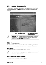
... Update only b e f o r e installing Microsoft® Windows® XP Service Pack 1. Intel Chipset INF Update Program Installs the Intel® Chipset INF Update Program. Double-click the A S S E T U P . ASUS T2-PH1 3-3 E X E to activate the devices. 3.3.1 Running the support CD To begin using the support CD, place the CD in your computer. The CD automatically displays the D r i v e r s menu if Autorun is NOT enabled in your optical drive. QFE Update Installs the Quick Fix Engineering (QFE) driver updates...
... Update only b e f o r e installing Microsoft® Windows® XP Service Pack 1. Intel Chipset INF Update Program Installs the Intel® Chipset INF Update Program. Double-click the A S S E T U P . ASUS T2-PH1 3-3 E X E to activate the devices. 3.3.1 Running the support CD To begin using the support CD, place the CD in your computer. The CD automatically displays the D r i v e r s menu if Autorun is NOT enabled in your optical drive. QFE Update Installs the Quick Fix Engineering (QFE) driver updates...
User Guide
Page 55
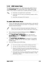
...See section "4.4 Connectors" for the location of the CD connector. In the I n s t a n t M u s i c C o n f i g u r a t i o n menu, select the item I n s t a n t M u s i c and set to E n a b l e d. R O M D r i v e item appears if you cannot control the audio volume using the power switch. • If the system lost connection or did not detect any optical drive, the Instant Music feature turns OFF (disabled) automatically. A "beep" indicates this case, power up features (LAN, keyboard, mouse, USB) are deactivated. Make sure to display the CD-ROM options. 5. Turn on sound card. •...
...See section "4.4 Connectors" for the location of the CD connector. In the I n s t a n t M u s i c C o n f i g u r a t i o n menu, select the item I n s t a n t M u s i c and set to E n a b l e d. R O M D r i v e item appears if you cannot control the audio volume using the power switch. • If the system lost connection or did not detect any optical drive, the Instant Music feature turns OFF (disabled) automatically. A "beep" indicates this case, power up features (LAN, keyboard, mouse, USB) are deactivated. Make sure to display the CD-ROM options. 5. Turn on sound card. •...
User Guide
Page 56
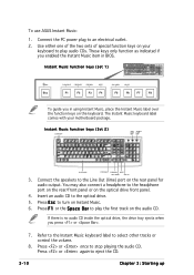
... audio CD. If there is no audio CD inside the optical drive, the drive tray ejects when you enabled the Instant Music item in using Instant Music, place the Instant Music label over the function keys on Instant Music. 6. Connect the PC power plug to play audio CDs. These keys only function as indicated if you press or . 7. To use ASUS Instant Music: 1. Instant Music function keys (Set...
... audio CD. If there is no audio CD inside the optical drive, the drive tray ejects when you enabled the Instant Music item in using Instant Music, place the Instant Music label over the function keys on Instant Music. 6. Connect the PC power plug to play audio CDs. These keys only function as indicated if you press or . 7. To use ASUS Instant Music: 1. Instant Music function keys (Set...
User Guide
Page 80
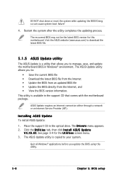
... you update the BIOS using this motherboard. X X. DO NOT shut down or reset the system while updating the BIOS! Visit the ASUS website (www.asus.com) to download the latest BIOS file. 5.1.5 ASUS Update utility The ASUS Update is a utility that allows you to manage, save, and update the motherboard BIOS in the support CD that comes with the motherboard package. ASUS Update requires an Internet connection either through a network or an Internet Service Provider (ISP). The D r i v e r s menu appears. 2. Quit all Windows...
... you update the BIOS using this motherboard. X X. DO NOT shut down or reset the system while updating the BIOS! Visit the ASUS website (www.asus.com) to download the latest BIOS file. 5.1.5 ASUS Update utility The ASUS Update is a utility that allows you to manage, save, and update the motherboard BIOS in the support CD that comes with the motherboard package. ASUS Update requires an Internet connection either through a network or an Internet Service Provider (ISP). The D r i v e r s menu appears. 2. Quit all Windows...
User Guide
Page 83
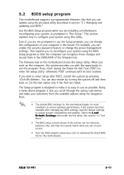
.... ASUS T2-PH1 5-11 5.2 BIOS setup program This motherboard supports a programmable firmware chip that the computer can recognize these changes and record them in the CMOS RAM of your system, or prompted to "Run Setup." This requires you wish to enter Setup after changing any BIOS settings, load the default settings to enter the Setup utility; otherwise, POST continues with the opportunity to ensure optimum performance. The firmware hub on your system using the navigation keys...
.... ASUS T2-PH1 5-11 5.2 BIOS setup program This motherboard supports a programmable firmware chip that the computer can recognize these changes and record them in the CMOS RAM of your system, or prompted to "Run Setup." This requires you wish to enter Setup after changing any BIOS settings, load the default settings to enter the Setup utility; otherwise, POST continues with the opportunity to ensure optimum performance. The firmware hub on your system using the navigation keys...
User Guide
Page 87
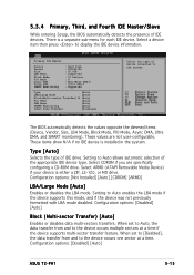
... and SMART monitoring). Setting to display the IDE device information. 5.3.4 Primary, Third, and Fourth IDE Master/Slave While entering Setup, the BIOS automatically detects the presence of the appropriate IDE device type. These values are specifically configuring a CD-ROM drive. Configuration options: [Not Installed] [Auto] [CDROM] [ARMD] LBA/Large Mode [Auto] Enables or disables the LBA mode. Configuration options: [Disabled] [Auto] Block (Multi-sector Transfer) [Auto] Enables or disables data multi-sectors transfers. Configuration options: [Disabled] [Auto] ASUS T2-PH1 5-15...
... and SMART monitoring). Setting to display the IDE device information. 5.3.4 Primary, Third, and Fourth IDE Master/Slave While entering Setup, the BIOS automatically detects the presence of the appropriate IDE device type. These values are specifically configuring a CD-ROM drive. Configuration options: [Not Installed] [Auto] [CDROM] [ARMD] LBA/Large Mode [Auto] Enables or disables the LBA mode. Configuration options: [Disabled] [Auto] Block (Multi-sector Transfer) [Auto] Enables or disables data multi-sectors transfers. Configuration options: [Disabled] [Auto] ASUS T2-PH1 5-15...
User Guide
Page 94
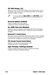
...adjust the values. In C1E mode, the CPU power consumption is auto-detected by BIOS. Configuration options: [Auto] [Disabled] CPU Internal Thermal Control [Auto] Disables or sets the CPU internal thermal control. Configuration options: [Auto] [Disabled] Hyper Threading Technology [Enabled] Enables or disables the processor Hyper-Threading Technology. Configuration options: [Disabled] [Enabled] Enhanced C1 Control [Auto] When set the VID CMOS setting at which the processor is to enable the C1E support. VID CMOS Setting [ 62] Allows you installed an unlocked CPU. You can only adjust...
...adjust the values. In C1E mode, the CPU power consumption is auto-detected by BIOS. Configuration options: [Auto] [Disabled] CPU Internal Thermal Control [Auto] Disables or sets the CPU internal thermal control. Configuration options: [Auto] [Disabled] Hyper Threading Technology [Enabled] Enables or disables the processor Hyper-Threading Technology. Configuration options: [Disabled] [Enabled] Enhanced C1 Control [Auto] When set the VID CMOS setting at which the processor is to enable the C1E support. VID CMOS Setting [ 62] Allows you installed an unlocked CPU. You can only adjust...
User Guide
Page 107
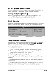
... box, type a password composed of the screen shows the default N o t I n s t a l l e d. To clear the supervisor password, select the Change Supervisor Password then press . ASUS T2-PH1 5-35 Security Settings Supervisor Password : Not Installed User Password : Not Installed Change Supervisor Password Boot Sector Virus Protection [Disabled] to change the supervisor password, follow the same steps as in setting a user password. To set a Supervisor Password: 1. The message "Password Installed" appears after you set a password, this function allows the option ROMs to run Setup...
... box, type a password composed of the screen shows the default N o t I n s t a l l e d. To clear the supervisor password, select the Change Supervisor Password then press . ASUS T2-PH1 5-35 Security Settings Supervisor Password : Not Installed User Password : Not Installed Change Supervisor Password Boot Sector Virus Protection [Disabled] to change the supervisor password, follow the same steps as in setting a user password. To set a Supervisor Password: 1. The message "Password Installed" appears after you set a password, this function allows the option ROMs to run Setup...
User Guide
Page 108
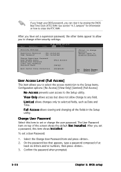
... Access] N o A c c e s s prevents user access to the Setup utility. L i m i t e d allows changes only to any field. After you have set a User Password: 1. User Access Level (Full Access] This item allows you can clear it by erasing the CMOS Real Time Clock (RTC) RAM. On the password box that appears, type a password composed of the screen shows the default N o t I n s t a l l e d. See section "4.3 Jumpers" for information on top of at least six letters and/or numbers, then...
... Access] N o A c c e s s prevents user access to the Setup utility. L i m i t e d allows changes only to any field. After you have set a User Password: 1. User Access Level (Full Access] This item allows you can clear it by erasing the CMOS Real Time Clock (RTC) RAM. On the password box that appears, type a password composed of the screen shows the default N o t I n s t a l l e d. See section "4.3 Jumpers" for information on top of at least six letters and/or numbers, then...


