T2-P User Manual
Page 8
... the BIOS Setup menus and describes the BIOS parameters. 6. Chapter 4: Motherboard information This chapter gives information about the ASUS Terminator 2 barebone system. Appendix The Appendix includes the power supply unit specification and IEEE 802.11b channels for experienced users and integrators ...with hardware knowledge of the ASUS Terminator 2. This guide is organized This guide contains the following parts: 1. The chapter lists ...
... the BIOS Setup menus and describes the BIOS parameters. 6. Chapter 4: Motherboard information This chapter gives information about the ASUS Terminator 2 barebone system. Appendix The Appendix includes the power supply unit specification and IEEE 802.11b channels for experienced users and integrators ...with hardware knowledge of the ASUS Terminator 2. This guide is organized This guide contains the following parts: 1. The chapter lists ...
T2-P User Manual
Page 10
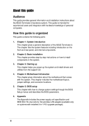
... ATA cable • Serial ATA power cable 3. Item description T2-P models Deluxe Standard 1. System package contents Check your Terminator 2 system package for the following items. If any of the items is damaged or missing, contact your retailer immediately. ASUS Terminator 2 barebone system with • ASUS P4P8T motherboard • Floppy disk drive • 7-in -1 PCI...
... ATA cable • Serial ATA power cable 3. Item description T2-P models Deluxe Standard 1. System package contents Check your Terminator 2 system package for the following items. If any of the items is damaged or missing, contact your retailer immediately. ASUS Terminator 2 barebone system with • ASUS P4P8T motherboard • Floppy disk drive • 7-in -1 PCI...
T2-P User Manual
Page 11
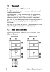
MODE ASUS Terminator 2 barebone system The chapter lists the system features including introduction on the front and rear panel, and internal components. System introduction Chapter 1 This chapter gives a general description of the ASUS Terminator 2.
MODE ASUS Terminator 2 barebone system The chapter lists the system features including introduction on the front and rear panel, and internal components. System introduction Chapter 1 This chapter gives a general description of the ASUS Terminator 2.
T2-P User Manual
Page 12
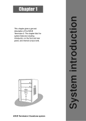
... Terminator 2 is an all-in a stylish mini-tower casing, and powered by the ASUS P4P8T motherboard that supports Intel® Pentium® 4 Northwood/ Prescott processor with a versatile home entertainment feature. The ASUS Terminator 2 is designed for the sophisticated. Deluxe model 1 2 Standard model 1 2 ...3 4 9 10 MODE 5 6 7 8 11 12 13 14 MODE 3 4 5 6 7 8 15 16 17 18 12 Chapter 1: System introduction The system comes in -one barebone system with 800MHz FSB...
... Terminator 2 is an all-in a stylish mini-tower casing, and powered by the ASUS P4P8T motherboard that supports Intel® Pentium® 4 Northwood/ Prescott processor with a versatile home entertainment feature. The ASUS Terminator 2 is designed for the sophisticated. Deluxe model 1 2 Standard model 1 2 ...3 4 9 10 MODE 5 6 7 8 11 12 13 14 MODE 3 4 5 6 7 8 15 16 17 18 12 Chapter 1: System introduction The system comes in -one barebone system with 800MHz FSB...
T2-P User Manual
Page 13
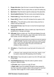
... presets a station when pressed for details. Refer to play CD audio tracks, or tune into an FM radio station without entering the operating system. ASUS Terminator 2 barebone system 13 This door opens when you to page 60 on deluxe models only. 11. When lit, this door to FM radio mode or vice...
... presets a station when pressed for details. Refer to play CD audio tracks, or tune into an FM radio station without entering the operating system. ASUS Terminator 2 barebone system 13 This door opens when you to page 60 on deluxe models only. 11. When lit, this door to FM radio mode or vice...
T2-P User Manual
Page 15
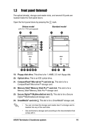
...®/Memory Stick Pro™ storage card. 23. Floppy disk drive. Optical drive. CompactFlash®/Microdrive™ card slot . Secure Digital™/MultimediaCard slot . ASUS Terminator 2 barebone system 15 This slot is for a Secure Digital™/MultimediaCard storage card. 24. This slot is inserted into any of the card slots. • Use...
...®/Memory Stick Pro™ storage card. 23. Floppy disk drive. Optical drive. CompactFlash®/Microdrive™ card slot . Secure Digital™/MultimediaCard slot . ASUS Terminator 2 barebone system 15 This slot is for a Secure Digital™/MultimediaCard storage card. 24. This slot is inserted into any of the card slots. • Use...

T2-P User Manual
Page 17
Serial port . PS/2 mouse port . ASUS Terminator 2 barebone system 17 Deluxe model (with serial specification. 5. This port connects an RJ-11 cable jack. Telephone port (optional). Connect one end of devices. PS/2 keyboard ...
Serial port . PS/2 mouse port . ASUS Terminator 2 barebone system 17 Deluxe model (with serial specification. 5. This port connects an RJ-11 cable jack. Telephone port (optional). Connect one end of devices. PS/2 keyboard ...
T2-P User Manual
Page 19
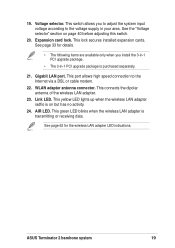
... voltage according to the Internet via a DSL or cable modem. 22. Voltage selector. This connects the dipolar antenna of the wireless LAN adapter. 23. ASUS Terminator 2 barebone system 19 See the "Voltage selector" section on but has no activity. 24. See page 33 for the wireless LAN adapter LED indications. This lock...
... voltage according to the Internet via a DSL or cable modem. 22. Voltage selector. This connects the dipolar antenna of the wireless LAN adapter. 23. ASUS Terminator 2 barebone system 19 See the "Voltage selector" section on but has no activity. 24. See page 33 for the wireless LAN adapter LED indications. This lock...
T2-P User Manual
Page 21
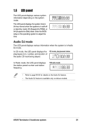
...; Refer to page 59-60 for details on the Audio DJ feature. • The Audio DJ feature is available only on the system mode. ASUS Terminator 2 barebone system 21 In CD mode, the LED panel displays the CD mode, play/paused status play/pause icon, number, and duration of the audio CD...
...; Refer to page 59-60 for details on the Audio DJ feature. • The Audio DJ feature is available only on the system mode. ASUS Terminator 2 barebone system 21 In CD mode, the LED panel displays the CD mode, play/paused status play/pause icon, number, and duration of the audio CD...
T2-P User Manual
Page 23
Basic installation Chapter 2 This chapter provides step-by-step instructions on how to install components in the system. MODE ASUS Terminator 2 barebone system
Basic installation Chapter 2 This chapter provides step-by-step instructions on how to install components in the system. MODE ASUS Terminator 2 barebone system
T2-P User Manual
Page 25
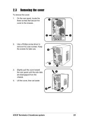
Slightly pull the cover toward the rear panel until the side tabs are disengaged from the chassis. 4. Lift the cover, then set aside. 2 2 4 3 3 ASUS Terminator 2 barebone system 25 Use a Phillips screw driver to the chassis. 1 1 2. Keep the screws for later use. 2 3. 2.3 Removing the cover To remove the cover: 1. On the rear panel, locate the three screws that secure the 1 cover to remove the cover screws.
Slightly pull the cover toward the rear panel until the side tabs are disengaged from the chassis. 4. Lift the cover, then set aside. 2 2 4 3 3 ASUS Terminator 2 barebone system 25 Use a Phillips screw driver to the chassis. 1 1 2. Keep the screws for later use. 2 3. 2.3 Removing the cover To remove the cover: 1. On the rear panel, locate the three screws that secure the 1 cover to remove the cover screws.

T2-P User Manual
Page 27
... the CPU fan and heatsink assembly The system package includes a pre-installed proprietary CPU fan and heatsink assembly to remove the second retention bracket. 4 ASUS Terminator 2 barebone system 3 27 Detach the other retention bracket hook from the retention module hole by flipping the locking lever 2 to the direction of the arrow. 3. Carefully...
... the CPU fan and heatsink assembly The system package includes a pre-installed proprietary CPU fan and heatsink assembly to remove the second retention bracket. 4 ASUS Terminator 2 barebone system 3 27 Detach the other retention bracket hook from the retention module hole by flipping the locking lever 2 to the direction of the arrow. 3. Carefully...
T2-P User Manual
Page 29
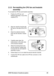
... press down the locking lever on the motherboard. Follow steps 2 to 5 to the CPU fan connector on the other side of the CPU fan. 3. ASUS Terminator 2 barebone system 29 Align the retention bracket with the rails on top of the installed CPU. 1 2. Position the CPU fan and heatsink assembly on the side...
... press down the locking lever on the motherboard. Follow steps 2 to 5 to the CPU fan connector on the other side of the CPU fan. 3. ASUS Terminator 2 barebone system 29 Align the retention bracket with the rails on top of the installed CPU. 1 2. Position the CPU fan and heatsink assembly on the side...
T2-P User Manual
Page 31
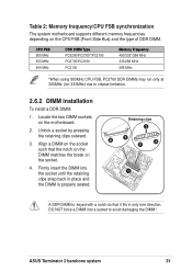
.../266 MHz 266 MHz *When using 800MHz CPU FSB, PC2700 DDR DIMMs may run only at 320MHz (not 333MHz) due to avoid damaging the DIMM! ASUS Terminator 2 barebone system 31 Align a DIMM on the socket. 4.
.../266 MHz 266 MHz *When using 800MHz CPU FSB, PC2700 DDR DIMMs may run only at 320MHz (not 333MHz) due to avoid damaging the DIMM! ASUS Terminator 2 barebone system 31 Align a DIMM on the socket. 4.
T2-P User Manual
Page 33
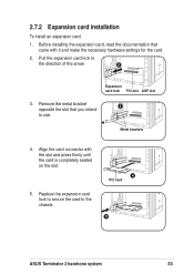
... the card to the direction of the arrow. 2 Expansion card lock PCI slot AGP slot 3. Pull the expansion card lock to the chassis. 4 PCI card 5 ASUS Terminator 2 barebone system 33 Metal brackets 4.
... the card to the direction of the arrow. 2 Expansion card lock PCI slot AGP slot 3. Pull the expansion card lock to the chassis. 4 PCI card 5 ASUS Terminator 2 barebone system 33 Metal brackets 4.
T2-P User Manual
Page 35
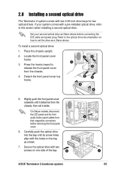
... drives. Carefully push the optical drive into the bay until it aside. Set your system comes with two screws on one side of the bay. 6 5 7 ASUS Terminator 2 barebone system 35 Press the hooks inward to this section when installing a second optical drive. Detach the front panel cover top hooks. 3 3 1 2 3 3 4 4 5. Place the chassis...
... drives. Carefully push the optical drive into the bay until it aside. Set your system comes with two screws on one side of the bay. 6 5 7 ASUS Terminator 2 barebone system 35 Press the hooks inward to this section when installing a second optical drive. Detach the front panel cover top hooks. 3 3 1 2 3 3 4 4 5. Place the chassis...
T2-P User Manual
Page 37
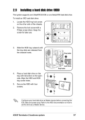
Remove the lock screw with four screws. Slide the HDD tray outward until the tray slots are released from the chassis hooks. Tray locks 3 4. ASUS Terminator 2 barebone system 37 Place a hard disk drive on the tray with its bottom on how to set the drive as Master device before connecting the IDE ...
Remove the lock screw with four screws. Slide the HDD tray outward until the tray slots are released from the chassis hooks. Tray locks 3 4. ASUS Terminator 2 barebone system 37 Place a hard disk drive on the tray with its bottom on how to set the drive as Master device before connecting the IDE ...
T2-P User Manual
Page 39
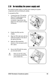
... the screw you removed earlier. To reinstall the PSU: 1. Make sure the PSU cables do not interfere with the CPU and/or chassis fans. 5 ASUS Terminator 2 barebone system 39 Slide the PSU toward the direction of these connectors. 1 2. 2.10 Re-installing the power supply unit Re-install the power supply unit (PSU...
... the screw you removed earlier. To reinstall the PSU: 1. Make sure the PSU cables do not interfere with the CPU and/or chassis fans. 5 ASUS Terminator 2 barebone system 39 Slide the PSU toward the direction of these connectors. 1 2. 2.10 Re-installing the power supply unit Re-install the power supply unit (PSU...

T2-P User Manual
Page 41
Fit the cover tabs with three screws you earlier removed. 5 ASUS Terminator 2 barebone system 41 Secure the cover with the chassis rail and the front panel tabs. 3. Position the front edge of the cover as shown. 4. Lower the rear edge of the cover at least two inches from 3 the front panel cover. 2.11 Replacing the cover To replace the cover. 1. Push the cover slightly toward 2 the front panel until it fits in 4 place. 5. Turn the chassis upright. 2.
Fit the cover tabs with three screws you earlier removed. 5 ASUS Terminator 2 barebone system 41 Secure the cover with the chassis rail and the front panel tabs. 3. Position the front edge of the cover as shown. 4. Lower the rear edge of the cover at least two inches from 3 the front panel cover. 2.11 Replacing the cover To replace the cover. 1. Push the cover slightly toward 2 the front panel until it fits in 4 place. 5. Turn the chassis upright. 2.

T2-P User Manual
Page 43
To the rear panel Telephone Joystick Serial mouse PS/2 KB VGA monitor Recorder Card Reader RJ-11 socket RJ-45 Mic PS/2 Mouse Printer Line Out Power outlet ASUS Terminator 2 barebone system 43
To the rear panel Telephone Joystick Serial mouse PS/2 KB VGA monitor Recorder Card Reader RJ-11 socket RJ-45 Mic PS/2 Mouse Printer Line Out Power outlet ASUS Terminator 2 barebone system 43

