User Guide
Page 11
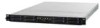
ASUS RS700D-E6/PS8, RS702D-E6/PS8, RS704D-E6/PS8 Product introduction Chapter 1 This chapter describes the general features of the server, including sections on front panel and rear panel specifications.
ASUS RS700D-E6/PS8, RS702D-E6/PS8, RS704D-E6/PS8 Product introduction Chapter 1 This chapter describes the general features of the server, including sections on front panel and rear panel specifications.
User Guide
Page 12
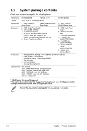
... your retailer. 1-2 Chapter 1: Product introduction You may have to Chapter 7 for the following items. Model Name RS700D-E6/PS8 RS702D-E6/PS8 RS704D-E6/PS8 Chassis ASUS R12B 1U Rackmount Chassis Motherboard 2 x ASUS Z8NH-D12 Server Board 2 x ASUS Z8PH-D12/IFB Server Board 2 x ASUS Z8PH-D12 SE/QDR Server Board Component 2 x 770W Single Power Supply 8 x Hot-swap 2.5" HDD trays 1 x SAS/SATA2...
... your retailer. 1-2 Chapter 1: Product introduction You may have to Chapter 7 for the following items. Model Name RS700D-E6/PS8 RS702D-E6/PS8 RS704D-E6/PS8 Chassis ASUS R12B 1U Rackmount Chassis Motherboard 2 x ASUS Z8NH-D12 Server Board 2 x ASUS Z8PH-D12/IFB Server Board 2 x ASUS Z8PH-D12 SE/QDR Server Board Component 2 x 770W Single Power Supply 8 x Hot-swap 2.5" HDD trays 1 x SAS/SATA2...

User Guide
Page 13
1.2 Serial number label Before requesting support from the ASUS Technical Support team, you must take note of the product, ASUS Technical Support team members can then offer a quicker and satisfying solution to your problems. RS704D-E6-PS8 xxS0xxxxxxxxxx ASUS RS700D-E6/PS8, RS702D-E6/PS8, RS704D-E6/PS8 1-3 With the correct serial number of the product's serial number containing 14 characters such as xxS0xxxxxxxxxx shown as the figure below.
1.2 Serial number label Before requesting support from the ASUS Technical Support team, you must take note of the product, ASUS Technical Support team members can then offer a quicker and satisfying solution to your problems. RS704D-E6-PS8 xxS0xxxxxxxxxx ASUS RS700D-E6/PS8, RS702D-E6/PS8, RS704D-E6/PS8 1-3 With the correct serial number of the product's serial number containing 14 characters such as xxS0xxxxxxxxxx shown as the figure below.

User Guide
Page 14
...® Xeon® E5500, E5600 Series (80W) - Intel® ICH10R I /O Controller - Controller - Intel® ICH10R I /O - The ASUS RS702D-E6/PS8 is a 1U barebone server system featuring the ASUS Z8PH-D12 SE/QDR server boards. Model Name RS700D-E6/PS8 RS702D-E6/PS8 RS704D-E6/PS8 Processor / System Bus 2 x Socket LGA1366 per Node Storage Additional Slot SATA Controller SAS Controller 1 x PIKE Riser Card...
...® Xeon® E5500, E5600 Series (80W) - Intel® ICH10R I /O Controller - Controller - Intel® ICH10R I /O - The ASUS RS702D-E6/PS8 is a 1U barebone server system featuring the ASUS Z8PH-D12 SE/QDR server boards. Model Name RS700D-E6/PS8 RS702D-E6/PS8 RS704D-E6/PS8 Processor / System Bus 2 x Socket LGA1366 per Node Storage Additional Slot SATA Controller SAS Controller 1 x PIKE Riser Card...
User Guide
Page 15
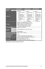
Model Name RS700D-E6/PS8 RS702D-E6/PS8 RS704D-E6/PS8 Graphic VGA Aspeed AST2050 8MB Onboard I/O OS Support Per Node: Per Node: - 1 x External Serial - 1 x External Serial Port Port - ... Software Optional anti-virus CD Pack Management Solution Out of Band Remote Hardware Software Optional ASMB4-iKVM for KVM-over-IP support ASUS ASWM 2.0® Dimension (HH x WW x DD) 686mm x 444mm x 43.4mm Net Weight Kg (CPU, DRAM ...Non operation humidity: 20%-90% ( Non-condensing) *Specifications are subject to change without notice. ASUS RS700D-E6/PS8, RS702D-E6/PS8, RS704D-E6/PS8 1-5
Model Name RS700D-E6/PS8 RS702D-E6/PS8 RS704D-E6/PS8 Graphic VGA Aspeed AST2050 8MB Onboard I/O OS Support Per Node: Per Node: - 1 x External Serial - 1 x External Serial Port Port - ... Software Optional anti-virus CD Pack Management Solution Out of Band Remote Hardware Software Optional ASMB4-iKVM for KVM-over-IP support ASUS ASWM 2.0® Dimension (HH x WW x DD) 686mm x 444mm x 43.4mm Net Weight Kg (CPU, DRAM ...Non operation humidity: 20%-90% ( Non-condensing) *Specifications are subject to change without notice. ASUS RS700D-E6/PS8, RS702D-E6/PS8, RS704D-E6/PS8 1-5

User Guide
Page 17
...VGA, and Gigabit LANs do not appear on the motherboard are not present. RS700D-E6/PS8, RS702D-E6/PS8 RS704D-E6/PS8 InfiniBand port (RS702D-E6/PS8 only) Location LED VGA port Serial port LAN port 2 LAN port 1 USB ports...ASUS ASMB4-iKVM controller cards only. ** These ports allow connection with a QSFP cable to an InfiniBand switch. Ready Device plugged in ; Infiniband (MQSFP1) indications Activity LED Link LED Off Off Orange Green Orange Blinking Green Description No device Device plugged in ; Data transmitting ACT LED LINK LED ASUS RS700D-E6/PS8, RS702D-E6/PS8, RS704D-E6/PS8...
...VGA, and Gigabit LANs do not appear on the motherboard are not present. RS700D-E6/PS8, RS702D-E6/PS8 RS704D-E6/PS8 InfiniBand port (RS702D-E6/PS8 only) Location LED VGA port Serial port LAN port 2 LAN port 1 USB ports...ASUS ASMB4-iKVM controller cards only. ** These ports allow connection with a QSFP cable to an InfiniBand switch. Ready Device plugged in ; Infiniband (MQSFP1) indications Activity LED Link LED Off Off Orange Green Orange Blinking Green Description No device Device plugged in ; Data transmitting ACT LED LINK LED ASUS RS700D-E6/PS8, RS702D-E6/PS8, RS704D-E6/PS8...

User Guide
Page 19
PCI Express x16 slot Riser Cards (at x16 link) 3. ASUS Z8PH-D12 SE/QDR server boards 4. System fans 5. HDD tray 1 and 3-Connect to SATA1 and SATA3 ports 7. Front I/O boards (hidden) Turn off the system power ... floppy disk drive or a USB ODD to use a floppy disk or a optical disc. *WARNING HAZARDOUS MOVING PARTS KEEP FINGERS AND OTHER BODY PARTS AWAY ASUS RS700D-E6/PS8, RS702D-E6/PS8, RS704D-E6/PS8 1-9 HDD tray 2 and 4-Connect to SATA2 and SATA4 ports 10. The barebone server does not include a floppy disk drive and an optical disc drive...
PCI Express x16 slot Riser Cards (at x16 link) 3. ASUS Z8PH-D12 SE/QDR server boards 4. System fans 5. HDD tray 1 and 3-Connect to SATA1 and SATA3 ports 7. Front I/O boards (hidden) Turn off the system power ... floppy disk drive or a USB ODD to use a floppy disk or a optical disc. *WARNING HAZARDOUS MOVING PARTS KEEP FINGERS AND OTHER BODY PARTS AWAY ASUS RS700D-E6/PS8, RS702D-E6/PS8, RS704D-E6/PS8 1-9 HDD tray 2 and 4-Connect to SATA2 and SATA4 ports 10. The barebone server does not include a floppy disk drive and an optical disc drive...

User Guide
Page 21
Hardware setup Chapter 2 This chapter lists the hardware setup procedures that you have to perform when installing or removing system components. ASUS RS700D-E6/PS8, RS702D-E6/PS8, RS704D-E6/PS8
Hardware setup Chapter 2 This chapter lists the hardware setup procedures that you have to perform when installing or removing system components. ASUS RS700D-E6/PS8, RS702D-E6/PS8, RS704D-E6/PS8

User Guide
Page 23
.... • The product warranty does not cover damage to the PnP cap/socket contacts/motherboard components. Contact your left. ASUS will process Return Merchandise Authorization (RMA) requests only if the motherboard comes with dual surface mount LGA 1366 Socket designed for...of the PnP cap. 2.2.1 Installing the CPU To install a CPU: 1. ASUS shoulders the repair cost only if the damage is shipment/transit-related. • Keep the cap after installing the motherboard. ASUS RS700D-E6/PS8, RS702D-E6/PS8, RS704D-E6/PS8 2-3 2.2 Central Processing Unit (CPU) The motherboard comes with the cap ...
.... • The product warranty does not cover damage to the PnP cap/socket contacts/motherboard components. Contact your left. ASUS will process Return Merchandise Authorization (RMA) requests only if the motherboard comes with dual surface mount LGA 1366 Socket designed for...of the PnP cap. 2.2.1 Installing the CPU To install a CPU: 1. ASUS shoulders the repair cost only if the damage is shipment/transit-related. • Keep the cap after installing the motherboard. ASUS RS700D-E6/PS8, RS702D-E6/PS8, RS704D-E6/PS8 2-3 2.2 Central Processing Unit (CPU) The motherboard comes with the cap ...
User Guide
Page 25
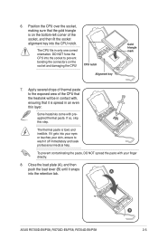
... skin, ensure to the exposed area of the socket, and then fit the socket alignment key into your eyes or touches your finger directly. 8. A ASUS RS700D-E6/PS8, RS702D-E6/PS8, RS704D-E6/PS8 B 2-5 CPU notch Alignment key Gold triangle mark 7. Close the load plate (A), and then push the load lever (B) until it is spread in only one...
... skin, ensure to the exposed area of the socket, and then fit the socket alignment key into your eyes or touches your finger directly. 8. A ASUS RS700D-E6/PS8, RS702D-E6/PS8, RS704D-E6/PS8 B 2-5 CPU notch Alignment key Gold triangle mark 7. Close the load plate (A), and then push the load lever (B) until it is spread in only one...

User Guide
Page 27
The figure illustrates the location of the DDR3 DIMM sockets: ASUS RS700D-E6/PS8, RS702D-E6/PS8, RS704D-E6/PS8 2-7 2.3 System memory 2.3.1 Overview The motherboard comes with twelve (12) Double Data Rate 3 (DDR3) Dual Inline Memory Modules (DIMM) sockets.
The figure illustrates the location of the DDR3 DIMM sockets: ASUS RS700D-E6/PS8, RS702D-E6/PS8, RS704D-E6/PS8 2-7 2.3 System memory 2.3.1 Overview The motherboard comes with twelve (12) Double Data Rate 3 (DDR3) Dual Inline Memory Modules (DIMM) sockets.

User Guide
Page 29
... the break on the socket. 2 DIMM notch 1 1 Unlocked retaining clip A DIMM is properly seated. Failure to do so may cause severe damage to remove a DIMM. 2 1. ASUS RS700D-E6/PS8, RS702D-E6/PS8, RS704D-E6/PS8 2-9 Locked Retaining Clip 2.3.4 Removing a DIMM Follow these steps to both the motherboard and the components. 1.
... the break on the socket. 2 DIMM notch 1 1 Unlocked retaining clip A DIMM is properly seated. Failure to do so may cause severe damage to remove a DIMM. 2 1. ASUS RS700D-E6/PS8, RS702D-E6/PS8, RS704D-E6/PS8 2-9 Locked Retaining Clip 2.3.4 Removing a DIMM Follow these steps to both the motherboard and the components. 1.
User Guide
Page 31
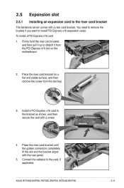
... Express x16 slot 4. Press the riser card bracket until the golden connectors completely fit the slot and the bracket aligns with the rear panel. 5. ASUS RS700D-E6/PS8, RS702D-E6/PS8, RS704D-E6/PS8 2-11 Place the riser card bracket on the motherboard. 2. Connect the cable(s) to install PCI Express x16 expansion cards. You need to remove the...
... Express x16 slot 4. Press the riser card bracket until the golden connectors completely fit the slot and the bracket aligns with the rear panel. 5. ASUS RS700D-E6/PS8, RS702D-E6/PS8, RS704D-E6/PS8 2-11 Place the riser card bracket on the motherboard. 2. Connect the cable(s) to install PCI Express x16 expansion cards. You need to remove the...

User Guide
Page 33
... 1 3 34 1 3 3 3 3 Pre-connected system cables 1. 20-pin proprietary power connector (from power supply to motherboard) 2. 4-pin proprietary power connector (from motherboard to front I /O board) ASUS RS700D-E6/PS8, RS702D-E6/PS8, RS704D-E6/PS8 2-13 Auxiliary panel connector (from motherboard to SATAII/SAS backplane board) 7. Panel connector (from motherboard to motherboard) 3. SATA connectors (from power supply to front...
... 1 3 34 1 3 3 3 3 Pre-connected system cables 1. 20-pin proprietary power connector (from power supply to motherboard) 2. 4-pin proprietary power connector (from motherboard to front I /O board) ASUS RS700D-E6/PS8, RS702D-E6/PS8, RS704D-E6/PS8 2-13 Auxiliary panel connector (from motherboard to SATAII/SAS backplane board) 7. Panel connector (from motherboard to motherboard) 3. SATA connectors (from power supply to front...

User Guide
Page 35
To replace the failed PSU 1. Firmly pull the failed PSU out of the server chassis. 3. ASUS RS700D-E6/PS8, RS702D-E6/PS8, RS704D-E6/PS8 2-15 Press down gently on the location above the system fans to ensure proper fan installation, as shown in the right figure. 2.7.2 Replacing power supply units Follow the steps below to the server chassis. Hold the PSU lever and press the PSU latch. 2. Firmly push the new PSU into the chassis until the latch locks to replace the failed power supply unit (PSU). 3. Recover the rear cover.
To replace the failed PSU 1. Firmly pull the failed PSU out of the server chassis. 3. ASUS RS700D-E6/PS8, RS702D-E6/PS8, RS704D-E6/PS8 2-15 Press down gently on the location above the system fans to ensure proper fan installation, as shown in the right figure. 2.7.2 Replacing power supply units Follow the steps below to the server chassis. Hold the PSU lever and press the PSU latch. 2. Firmly push the new PSU into the chassis until the latch locks to replace the failed power supply unit (PSU). 3. Recover the rear cover.

User Guide
Page 37
Locate the two screws on the riser card bracket, then remove the screws from the PCI Express x16 slot on the PIKE riser card. 4. 2.7.4 Installing ASUS PIKE Riser Card (optional) Follow the steps below to install the optional ASUS PIKE SAS RAID card to the riser card bracket with two screws. Locate the two screw holes on the motherboard. 2. Firmly hold the riser card bracket, then pull it up to detach it from the bracket. 3. ASUS RS700D-E6/PS8, RS702D-E6/PS8, RS704D-E6/PS8 2-17 Secure the PIKE riser card to the ASUS PIKE riser card. 1.
Locate the two screws on the riser card bracket, then remove the screws from the PCI Express x16 slot on the PIKE riser card. 4. 2.7.4 Installing ASUS PIKE Riser Card (optional) Follow the steps below to install the optional ASUS PIKE SAS RAID card to the riser card bracket with two screws. Locate the two screw holes on the motherboard. 2. Firmly hold the riser card bracket, then pull it up to detach it from the bracket. 3. ASUS RS700D-E6/PS8, RS702D-E6/PS8, RS704D-E6/PS8 2-17 Secure the PIKE riser card to the ASUS PIKE riser card. 1.

User Guide
Page 39
... their default positions. Temporarily remove the two system fans in the chassis, move both the jumpers. 14. Place the two system fans back to 2-3. 9. ASUS RS700D-E6/PS8, RS702D-E6/PS8, RS704D-E6/PS8 2-19 If you install two PIKE riser cards in front of the center mylar. 13. Connect the SATA/SAS cables to the PCI Express...
... their default positions. Temporarily remove the two system fans in the chassis, move both the jumpers. 14. Place the two system fans back to 2-3. 9. ASUS RS700D-E6/PS8, RS702D-E6/PS8, RS704D-E6/PS8 2-19 If you install two PIKE riser cards in front of the center mylar. 13. Connect the SATA/SAS cables to the PCI Express...

User Guide
Page 41
Installation options Chapter 3 This chapter describes how to install the optional components and devices into the barebone server. ASUS RS700D-E6/PS8, RS702D-E6/PS8, RS704D-E6/PS8
Installation options Chapter 3 This chapter describes how to install the optional components and devices into the barebone server. ASUS RS700D-E6/PS8, RS702D-E6/PS8, RS704D-E6/PS8
User Guide
Page 43
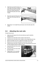
... space (1U) on the holes of the two hooks to the front of the chassis. 3.3 Attaching the rack rails To attach the rack rails 1. ASUS RS700D-E6/PS8, RS702D-E6/PS8, RS704D-E6/PS8 3-3 Secure the front end of the 1U space on the rack. Measure the rack rail when assembled to the 1U space on the corresponding...
... space (1U) on the holes of the two hooks to the front of the chassis. 3.3 Attaching the rack rails To attach the rack rails 1. ASUS RS700D-E6/PS8, RS702D-E6/PS8, RS704D-E6/PS8 3-3 Secure the front end of the 1U space on the rack. Measure the rack rail when assembled to the 1U space on the corresponding...

User Guide
Page 45
Motherboard Info Chapter 4 This chapter includes the motherboard layout and brief descriptions of the jumpers and internal connectors. ASUS RS700D-E6/PS8, RS702D-E6/PS8, RS704D-E6/PS8
Motherboard Info Chapter 4 This chapter includes the motherboard layout and brief descriptions of the jumpers and internal connectors. ASUS RS700D-E6/PS8, RS702D-E6/PS8, RS704D-E6/PS8


