
User Guide
Page 6
RS704D-E6/PS8 7-24 7.5.1 7.5.2 Windows operating system 7-24 Red Hat® Enterprise Linux OS 7-27 7.6 Management applications and utilities installation 7-29 7.6.1 Running the support DVD 7-29 7.6.2 Drivers menu 7-... driver 7-5 7.2 Intel® chipset device installation 7-17 7.3 LAN driver installation 7-19 7.4 VGA driver installation 7-22 7.5 Mellanox ConnectX DDR PCI Gen2 Channel Adapter driver installation (For RS702D-E6/PS8;
RS704D-E6/PS8 7-24 7.5.1 7.5.2 Windows operating system 7-24 Red Hat® Enterprise Linux OS 7-27 7.6 Management applications and utilities installation 7-29 7.6.1 Running the support DVD 7-29 7.6.2 Drivers menu 7-... driver 7-5 7.2 Intel® chipset device installation 7-17 7.3 LAN driver installation 7-19 7.4 VGA driver installation 7-22 7.5 Mellanox ConnectX DDR PCI Gen2 Channel Adapter driver installation (For RS702D-E6/PS8;
User Guide
Page 11
Product introduction Chapter 1 This chapter describes the general features of the server, including sections on front panel and rear panel specifications. ASUS RS700D-E6/PS8, RS702D-E6/PS8, RS704D-E6/PS8
Product introduction Chapter 1 This chapter describes the general features of the server, including sections on front panel and rear panel specifications. ASUS RS700D-E6/PS8, RS702D-E6/PS8, RS704D-E6/PS8
User Guide
Page 12
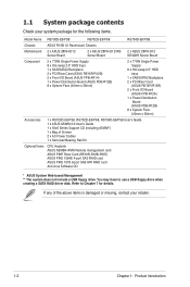
...to Chapter 7 for the following items. Model Name RS700D-E6/PS8 RS702D-E6/PS8 RS704D-E6/PS8 Chassis ASUS R12B 1U Rackmount Chassis Motherboard 2 x ASUS Z8NH-D12 Server Board 2 x ASUS Z8PH-D12/IFB Server Board 2 x ASUS Z8PH-D12 SE/QDR Server Board Component 2 x 770W ... trays 1 x SAS/SATA2 Backplane 2 x PCI Riser Card (ASUS RE16R-R12B) 2 x Front I/O Board (ASUS FPB-R12A) 1 x Power Distribution Board (ASUS PDB-R12B) 8 x System Fans (40mm x 56mm) Accessories 1 x RS700D-E6/PS8, RS702D-E6/PS8, RS704D-E6/PS8 User's Guide 1 x ASUS ASWM 2.0 User's Guide 1 x 55x0 Series Support CD (including...
...to Chapter 7 for the following items. Model Name RS700D-E6/PS8 RS702D-E6/PS8 RS704D-E6/PS8 Chassis ASUS R12B 1U Rackmount Chassis Motherboard 2 x ASUS Z8NH-D12 Server Board 2 x ASUS Z8PH-D12/IFB Server Board 2 x ASUS Z8PH-D12 SE/QDR Server Board Component 2 x 770W ... trays 1 x SAS/SATA2 Backplane 2 x PCI Riser Card (ASUS RE16R-R12B) 2 x Front I/O Board (ASUS FPB-R12A) 1 x Power Distribution Board (ASUS PDB-R12B) 8 x System Fans (40mm x 56mm) Accessories 1 x RS700D-E6/PS8, RS702D-E6/PS8, RS704D-E6/PS8 User's Guide 1 x ASUS ASWM 2.0 User's Guide 1 x 55x0 Series Support CD (including...

User Guide
Page 13
With the correct serial number of the product's serial number containing 14 characters such as xxS0xxxxxxxxxx shown as the figure below. 1.2 Serial number label Before requesting support from the ASUS Technical Support team, you must take note of the product, ASUS Technical Support team members can then offer a quicker and satisfying solution to your problems. RS704D-E6-PS8 xxS0xxxxxxxxxx ASUS RS700D-E6/PS8, RS702D-E6/PS8, RS704D-E6/PS8 1-3
With the correct serial number of the product's serial number containing 14 characters such as xxS0xxxxxxxxxx shown as the figure below. 1.2 Serial number label Before requesting support from the ASUS Technical Support team, you must take note of the product, ASUS Technical Support team members can then offer a quicker and satisfying solution to your problems. RS704D-E6-PS8 xxS0xxxxxxxxxx ASUS RS700D-E6/PS8, RS702D-E6/PS8, RS704D-E6/PS8 1-3

User Guide
Page 14
... Matrix Storage (for Storage Enhancement Intel® ICH10R: 4 x SATA2 300MB/s ports - The ASUS RS702D-E6/PS8 is a 1U barebone server system featuring the ASUS Z8NH-D12 server boards. Quad-Core Intel® Xeon® X5500, X5600 Series (95W) - Model Name RS700D-E6/PS8 RS702D-E6/PS8 RS704D-E6/PS8 Processor / System Bus 2 x Socket LGA1366 per Node Storage Additional Slot SATA Controller SAS...
... Matrix Storage (for Storage Enhancement Intel® ICH10R: 4 x SATA2 300MB/s ports - The ASUS RS702D-E6/PS8 is a 1U barebone server system featuring the ASUS Z8NH-D12 server boards. Quad-Core Intel® Xeon® X5500, X5600 Series (95W) - Model Name RS700D-E6/PS8 RS702D-E6/PS8 RS704D-E6/PS8 Processor / System Bus 2 x Socket LGA1366 per Node Storage Additional Slot SATA Controller SAS...
User Guide
Page 15
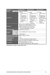
Model Name RS700D-E6/PS8 RS702D-E6/PS8 RS704D-E6/PS8 Graphic VGA Aspeed AST2050 8MB Onboard I/O OS Support Per Node: Per Node: - 1 x External Serial - 1 x External Serial Port Port - ... Software Optional anti-virus CD Pack Management Solution Out of Band Remote Hardware Software Optional ASMB4-iKVM for KVM-over-IP support ASUS ASWM 2.0® Dimension (HH x WW x DD) 686mm x 444mm x 43.4mm Net Weight Kg (CPU, DRAM ...Non operation humidity: 20%-90% ( Non-condensing) *Specifications are subject to change without notice. ASUS RS700D-E6/PS8, RS702D-E6/PS8, RS704D-E6/PS8 1-5
Model Name RS700D-E6/PS8 RS702D-E6/PS8 RS704D-E6/PS8 Graphic VGA Aspeed AST2050 8MB Onboard I/O OS Support Per Node: Per Node: - 1 x External Serial - 1 x External Serial Port Port - ... Software Optional anti-virus CD Pack Management Solution Out of Band Remote Hardware Software Optional ASMB4-iKVM for KVM-over-IP support ASUS ASWM 2.0® Dimension (HH x WW x DD) 686mm x 444mm x 43.4mm Net Weight Kg (CPU, DRAM ...Non operation humidity: 20%-90% ( Non-condensing) *Specifications are subject to change without notice. ASUS RS700D-E6/PS8, RS702D-E6/PS8, RS704D-E6/PS8 1-5

User Guide
Page 17
... No device Device plugged in ; Ready Device plugged in ; The I/O shields with a QSFP cable to an InfiniBand switch. RS700D-E6/PS8, RS702D-E6/PS8 RS704D-E6/PS8 InfiniBand port (RS702D-E6/PS8 only) Location LED VGA port Serial port LAN port 2 LAN port 1 USB ports LAN port* Power cord connector Power supply fan... VGA, and Gigabit LANs do not appear on the motherboard are not present. Data transmitting ACT LED LINK LED ASUS RS700D-E6/PS8, RS702D-E6/PS8, RS704D-E6/PS8 1-7 The ports for the rear panel connectors on the rear panel if the motherboards are also placed in the real panel.
... No device Device plugged in ; Ready Device plugged in ; The I/O shields with a QSFP cable to an InfiniBand switch. RS700D-E6/PS8, RS702D-E6/PS8 RS704D-E6/PS8 InfiniBand port (RS702D-E6/PS8 only) Location LED VGA port Serial port LAN port 2 LAN port 1 USB ports LAN port* Power cord connector Power supply fan... VGA, and Gigabit LANs do not appear on the motherboard are not present. Data transmitting ACT LED LINK LED ASUS RS700D-E6/PS8, RS702D-E6/PS8, RS704D-E6/PS8 1-7 The ports for the rear panel connectors on the rear panel if the motherboards are also placed in the real panel.

User Guide
Page 19
... a floppy disk or a optical disc. *WARNING HAZARDOUS MOVING PARTS KEEP FINGERS AND OTHER BODY PARTS AWAY ASUS RS700D-E6/PS8, RS702D-E6/PS8, RS704D-E6/PS8 1-9 HDD tray 1 and 3-Connect to SATA2 and SATA4 ports 10. RS704D-E6/PS4 2 2 11 3 3 4 5 67 89 10 10 1. ASUS Z8PH-D12 SE/QDR server boards 4. HDD tray 1 and 3-Connect to SATA2 and SATA4 ports...
... a floppy disk or a optical disc. *WARNING HAZARDOUS MOVING PARTS KEEP FINGERS AND OTHER BODY PARTS AWAY ASUS RS700D-E6/PS8, RS702D-E6/PS8, RS704D-E6/PS8 1-9 HDD tray 1 and 3-Connect to SATA2 and SATA4 ports 10. RS704D-E6/PS4 2 2 11 3 3 4 5 67 89 10 10 1. ASUS Z8PH-D12 SE/QDR server boards 4. HDD tray 1 and 3-Connect to SATA2 and SATA4 ports...

User Guide
Page 21
ASUS RS700D-E6/PS8, RS702D-E6/PS8, RS704D-E6/PS8 Hardware setup Chapter 2 This chapter lists the hardware setup procedures that you have to perform when installing or removing system components.
ASUS RS700D-E6/PS8, RS702D-E6/PS8, RS704D-E6/PS8 Hardware setup Chapter 2 This chapter lists the hardware setup procedures that you have to perform when installing or removing system components.

User Guide
Page 23
... removal of the motherboard, ensure that the socket box is facing towards you and the load lever is on your left. ASUS will process Return Merchandise Authorization (RMA) requests only if the motherboard comes with dual surface mount LGA 1366 Socket designed for the... package. • Upon purchase of the PnP cap. 2.2.1 Installing the CPU To install a CPU: 1. ASUS shoulders the repair cost only if the damage is on the motherboard. ASUS RS700D-E6/PS8, RS702D-E6/PS8, RS704D-E6/PS8 2-3 2.2 Central Processing Unit (CPU) The motherboard comes with the cap on the Socket 1366. •...
... removal of the motherboard, ensure that the socket box is facing towards you and the load lever is on your left. ASUS will process Return Merchandise Authorization (RMA) requests only if the motherboard comes with dual surface mount LGA 1366 Socket designed for the... package. • Upon purchase of the PnP cap. 2.2.1 Installing the CPU To install a CPU: 1. ASUS shoulders the repair cost only if the damage is on the motherboard. ASUS RS700D-E6/PS8, RS702D-E6/PS8, RS704D-E6/PS8 2-3 2.2 Central Processing Unit (CPU) The motherboard comes with the cap on the Socket 1366. •...
User Guide
Page 25
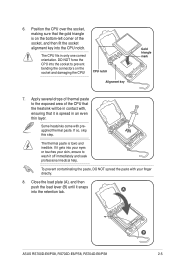
A ASUS RS700D-E6/PS8, RS702D-E6/PS8, RS704D-E6/PS8 B 2-5 DO NOT force the CPU into your eyes or touches your finger directly. 8. Some heatsinks come with your skin, ensure to wash it is spread ...
A ASUS RS700D-E6/PS8, RS702D-E6/PS8, RS704D-E6/PS8 B 2-5 DO NOT force the CPU into your eyes or touches your finger directly. 8. Some heatsinks come with your skin, ensure to wash it is spread ...

User Guide
Page 27
The figure illustrates the location of the DDR3 DIMM sockets: ASUS RS700D-E6/PS8, RS702D-E6/PS8, RS704D-E6/PS8 2-7 2.3 System memory 2.3.1 Overview The motherboard comes with twelve (12) Double Data Rate 3 (DDR3) Dual Inline Memory Modules (DIMM) sockets.
The figure illustrates the location of the DDR3 DIMM sockets: ASUS RS700D-E6/PS8, RS702D-E6/PS8, RS704D-E6/PS8 2-7 2.3 System memory 2.3.1 Overview The motherboard comes with twelve (12) Double Data Rate 3 (DDR3) Dual Inline Memory Modules (DIMM) sockets.

User Guide
Page 29
DO NOT force a DIMM into the socket until the retaining clips snap 3 back in only one direction. ASUS RS700D-E6/PS8, RS702D-E6/PS8, RS704D-E6/PS8 2-9 Failure to do so may cause severe damage to avoid damaging the DIMM. 3. Locked Retaining Clip 2.3.4 Removing a DIMM Follow these steps to unlock the DIMM. 1 1 ...
DO NOT force a DIMM into the socket until the retaining clips snap 3 back in only one direction. ASUS RS700D-E6/PS8, RS702D-E6/PS8, RS704D-E6/PS8 2-9 Failure to do so may cause severe damage to avoid damaging the DIMM. 3. Locked Retaining Clip 2.3.4 Removing a DIMM Follow these steps to unlock the DIMM. 1 1 ...
User Guide
Page 31
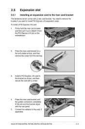
... x16 slot on a flat and stable surface, and then remove the screw from the slot bay. 3. Place the riser card bracket on the motherboard. 2. ASUS RS700D-E6/PS8, RS702D-E6/PS8, RS704D-E6/PS8 2-11 2.5 Expansion slot 2.5.1 Installing an expansion card to detach it up to the riser card bracket The barebone server comes with a riser card bracket...
... x16 slot on a flat and stable surface, and then remove the screw from the slot bay. 3. Place the riser card bracket on the motherboard. 2. ASUS RS700D-E6/PS8, RS702D-E6/PS8, RS704D-E6/PS8 2-11 2.5 Expansion slot 2.5.1 Installing an expansion card to detach it up to the riser card bracket The barebone server comes with a riser card bracket...

User Guide
Page 33
... connector (from motherboard to front I /O board) 5. Panel connector (from motherboard to front I/O board) 6. USB connector (from motherboard FRNT_FAN1, FRNT_FAN2, FRNT_FAN3 and FRNT_FAN4 to front I /O board) ASUS RS700D-E6/PS8, RS702D-E6/PS8, RS704D-E6/PS8 2-13 2.6 Cable connections • The bundled system cables are pre-connected before shipment. System fan connectors (from motherboard to system fans) 4.
... connector (from motherboard to front I /O board) 5. Panel connector (from motherboard to front I/O board) 6. USB connector (from motherboard FRNT_FAN1, FRNT_FAN2, FRNT_FAN3 and FRNT_FAN4 to front I /O board) ASUS RS700D-E6/PS8, RS702D-E6/PS8, RS704D-E6/PS8 2-13 2.6 Cable connections • The bundled system cables are pre-connected before shipment. System fan connectors (from motherboard to system fans) 4.

User Guide
Page 35
Press down gently on the location above the system fans to ensure proper fan installation, as shown in the right figure. 2.7.2 Replacing power supply units Follow the steps below to the server chassis. To replace the failed PSU 1. Firmly pull the failed PSU out of the server chassis. 3. Firmly push the new PSU into the chassis until the latch locks to replace the failed power supply unit (PSU). Hold the PSU lever and press the PSU latch. 2. 3. Recover the rear cover. ASUS RS700D-E6/PS8, RS702D-E6/PS8, RS704D-E6/PS8 2-15
Press down gently on the location above the system fans to ensure proper fan installation, as shown in the right figure. 2.7.2 Replacing power supply units Follow the steps below to the server chassis. To replace the failed PSU 1. Firmly pull the failed PSU out of the server chassis. 3. Firmly push the new PSU into the chassis until the latch locks to replace the failed power supply unit (PSU). Hold the PSU lever and press the PSU latch. 2. 3. Recover the rear cover. ASUS RS700D-E6/PS8, RS702D-E6/PS8, RS704D-E6/PS8 2-15

User Guide
Page 37
Locate the two screws on the motherboard. 2. Secure the PIKE riser card to the ASUS PIKE riser card. 1. Firmly hold the riser card bracket, then pull it up to detach it from the PCI Express x16 slot on the riser card bracket, then remove the screws from the bracket. 3. Locate the two screw holes on the PIKE riser card. 4. ASUS RS700D-E6/PS8, RS702D-E6/PS8, RS704D-E6/PS8 2-17 2.7.4 Installing ASUS PIKE Riser Card (optional) Follow the steps below to install the optional ASUS PIKE SAS RAID card to the riser card bracket with two screws.
Locate the two screws on the motherboard. 2. Secure the PIKE riser card to the ASUS PIKE riser card. 1. Firmly hold the riser card bracket, then pull it up to detach it from the PCI Express x16 slot on the riser card bracket, then remove the screws from the bracket. 3. Locate the two screw holes on the PIKE riser card. 4. ASUS RS700D-E6/PS8, RS702D-E6/PS8, RS704D-E6/PS8 2-17 2.7.4 Installing ASUS PIKE Riser Card (optional) Follow the steps below to install the optional ASUS PIKE SAS RAID card to the riser card bracket with two screws.

User Guide
Page 39
... golden fingers completely fit the slot and the bracket aligns with the rear panel. 12. 9. Move the SGPSEL1 jumper on the PIKE riser card. 10. ASUS RS700D-E6/PS8, RS702D-E6/PS8, RS704D-E6/PS8 2-19
... golden fingers completely fit the slot and the bracket aligns with the rear panel. 12. 9. Move the SGPSEL1 jumper on the PIKE riser card. 10. ASUS RS700D-E6/PS8, RS702D-E6/PS8, RS704D-E6/PS8 2-19

User Guide
Page 41
Installation options Chapter 3 This chapter describes how to install the optional components and devices into the barebone server. ASUS RS700D-E6/PS8, RS702D-E6/PS8, RS704D-E6/PS8
Installation options Chapter 3 This chapter describes how to install the optional components and devices into the barebone server. ASUS RS700D-E6/PS8, RS702D-E6/PS8, RS704D-E6/PS8
User Guide
Page 43
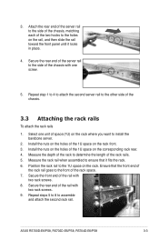
... of the two hooks to determine the length of the rail with two rack screws. 8. Install the nuts on the holes of the rack space. 7. ASUS RS700D-E6/PS8, RS702D-E6/PS8, RS704D-E6/PS8 3-3 Ensure that it locks in place. 4. Position the rack rail to the front of the 1U space on the corresponding rack rear. 4.
... of the two hooks to determine the length of the rail with two rack screws. 8. Install the nuts on the holes of the rack space. 7. ASUS RS700D-E6/PS8, RS702D-E6/PS8, RS704D-E6/PS8 3-3 Ensure that it locks in place. 4. Position the rack rail to the front of the 1U space on the corresponding rack rear. 4.