
User Manual
Page 5
CDROM Drives 5-31 5.7.3 Boot Settings Configuration 5-32 5.7.4 Security 5-33 5.8 Tools menu 5-35 5.8.1 ASUS EZ Flash 2 5-35 5.9 Exit menu 5-36 Chapter 6: RAID configuration 6.1 Setting up RAID 6-2 6.1.1 RAID definitions 6-2 6.1.2 Installing hard disk drives...22 5.4.6 ACPI Configuration 5-23 5.4.7 Event Log Configuration 5-25 5.4.8 Intel VT-d Configuration [Disabled 5-25 5.4.9 SR-IOV Supprted [Disabled 5-25 5.5 Server menu 5-26 5.6 Power menu 5-28 5.6.1 APM Configuration 5-28 5.6.2 Hardware Monitor 5-30 5.7 Boot menu 5-31 5.7.1 Boot Device Priority 5-31 5.7.2 Hard Disk Drives;
CDROM Drives 5-31 5.7.3 Boot Settings Configuration 5-32 5.7.4 Security 5-33 5.8 Tools menu 5-35 5.8.1 ASUS EZ Flash 2 5-35 5.9 Exit menu 5-36 Chapter 6: RAID configuration 6.1 Setting up RAID 6-2 6.1.1 RAID definitions 6-2 6.1.2 Installing hard disk drives...22 5.4.6 ACPI Configuration 5-23 5.4.7 Event Log Configuration 5-25 5.4.8 Intel VT-d Configuration [Disabled 5-25 5.4.9 SR-IOV Supprted [Disabled 5-25 5.5 Server menu 5-26 5.6 Power menu 5-28 5.6.1 APM Configuration 5-28 5.6.2 Hardware Monitor 5-30 5.7 Boot menu 5-31 5.7.1 Boot Device Priority 5-31 5.7.2 Hard Disk Drives;

User Manual
Page 8
...recommended by yourself. Dispose of explosion if battery is to be performed by trained service personnel only. • Before operating the server, carefully read all attached devices are not damaged. CD-ROM Drive Safety Warning CLASS 1 LASER PRODUCT Heavy System CAUTION! Ask for...manufacturer's instructions. Danger of used batteries according to or from the system, contact a qualified service technician or your dealer. Place the server on a stable surface. Safety information Electrical Safety • Before installing or removing signal cables, ensure that the power cables for the...
...recommended by yourself. Dispose of explosion if battery is to be performed by trained service personnel only. • Before operating the server, carefully read all attached devices are not damaged. CD-ROM Drive Safety Warning CLASS 1 LASER PRODUCT Heavy System CAUTION! Ask for...manufacturer's instructions. Danger of used batteries according to or from the system, contact a qualified service technician or your dealer. Place the server on a stable surface. Safety information Electrical Safety • Before installing or removing signal cables, ensure that the power cables for the...

User Manual
Page 9
...This chapter includes the motherboard layout and brief descriptions of electronic products. Chapter 5: BIOS information This chapter tells how to the barebone server 4. Chapter 6: RAID configuration This chapter provides instructions for setting up, creating and configuring RAID sets using the available utilities. 7...system components. 3. This symbol of the crossed out wheeled bin indicates that you have to enable proper reuse of the server, including sections on front panel and rear panel specifications. 2. Chapter 1: Product Introduction This chapter describes the general features...
...This chapter includes the motherboard layout and brief descriptions of electronic products. Chapter 5: BIOS information This chapter tells how to the barebone server 4. Chapter 6: RAID configuration This chapter provides instructions for setting up, creating and configuring RAID sets using the available utilities. 7...system components. 3. This symbol of the crossed out wheeled bin indicates that you have to enable proper reuse of the server, including sections on front panel and rear panel specifications. 2. Chapter 1: Product Introduction This chapter describes the general features...

User Manual
Page 10
...menu or an item to complete a task. Used to set up and use the proprietary ASUS server management utility. 2. If you MUST follow to help you must press the enclosed key. ASUS websites The ASUS websites worldwide provide updated information for product and software updates. 1. NOTE: Tips and additional... enclosed in the less-than and greater-than sign means that you must press the Enter or Return key. Keys enclosed in brackets. ASUS Server Web-based Management (ASWM) user guide This manual tells how to emphasize a word or a phrase. CAUTION: Information to prevent damage ...
...menu or an item to complete a task. Used to set up and use the proprietary ASUS server management utility. 2. If you MUST follow to help you must press the enclosed key. ASUS websites The ASUS websites worldwide provide updated information for product and software updates. 1. NOTE: Tips and additional... enclosed in the less-than and greater-than sign means that you must press the Enter or Return key. Keys enclosed in brackets. ASUS Server Web-based Management (ASWM) user guide This manual tells how to emphasize a word or a phrase. CAUTION: Information to prevent damage ...

User Manual
Page 11
Product introduction Chapter 1 This chapter describes the general features of the server, including sections on front panel and rear panel specifications.
Product introduction Chapter 1 This chapter describes the general features of the server, including sections on front panel and rear panel specifications.

User Manual
Page 12
... the following items. Model Name RS100-E6/PI2 Chassis ASUS R09 1U Rackmount Chassis Motherboard ASUS P7F-M Server Board Component 1 x 220W Single Power Supply 2 x SATA Cables 1 x PCI Express x16 Riser Card (PCIE16-R11) 1 x Front I/O Board (FPB-R9) 1 x USB Board (USB-R9) 2 x System Fans (40mm x 28mm) Accessories 1 x RS100-E6/PI2 User's Guide 1 x ASUS ASWM 2.0 User's Guide 1 x RS100-E6/PI2 Support CD (including ASWM*) 1 x Bag...
... the following items. Model Name RS100-E6/PI2 Chassis ASUS R09 1U Rackmount Chassis Motherboard ASUS P7F-M Server Board Component 1 x 220W Single Power Supply 2 x SATA Cables 1 x PCI Express x16 Riser Card (PCIE16-R11) 1 x Front I/O Board (FPB-R9) 1 x USB Board (USB-R9) 2 x System Fans (40mm x 28mm) Accessories 1 x RS100-E6/PI2 User's Guide 1 x ASUS ASWM 2.0 User's Guide 1 x RS100-E6/PI2 Support CD (including ASWM*) 1 x Bag...

User Manual
Page 13
... Serial Port 3 x RJ-45 ports (1 for ASMB4-iKVM) 4 x USB 2.0 ports (Front x 2, Rear x 2) 1 x VGA port 1 x PS/2 keyboard port 1 x PS/2 mouse port (continued on the next page) ASUS RS100-E6/PI2 1-3 1.3 System specifications The ASUS RS100-E6/PI2 is a 1U barebone server system featuring the ASUS P7F-M server board.
... Serial Port 3 x RJ-45 ports (1 for ASMB4-iKVM) 4 x USB 2.0 ports (Front x 2, Rear x 2) 1 x VGA port 1 x PS/2 keyboard port 1 x PS/2 mouse port (continued on the next page) ASUS RS100-E6/PI2 1-3 1.3 System specifications The ASUS RS100-E6/PI2 is a 1U barebone server system featuring the ASUS P7F-M server board.

User Manual
Page 14
...Hardware Software Net Weight Kg (CPU, DRAM & HDD not inclu ded) Dimension (DD x WW x HH) Power Supply Power Rating Environment Windows® Server 2008 Enterprise 32 / 64-bit Windows® Server 2003 R2 Enterprise 32 / 64-bit RedHat® Enterprise Linux AS5.0 32 / 64-bit SuSE® Linux Enterprise... Server 10 32 / 64-bit (Subject to change without any notice) Optional anti-virus CD Pack Optional ASMB4-iKVM for KVM-over-IP support ASUS ASWM 2.0® 6.5 Kg 380mm x 429.6mm x 43.2mm 220W Single Power Supply...
...Hardware Software Net Weight Kg (CPU, DRAM & HDD not inclu ded) Dimension (DD x WW x HH) Power Supply Power Rating Environment Windows® Server 2008 Enterprise 32 / 64-bit Windows® Server 2003 R2 Enterprise 32 / 64-bit RedHat® Enterprise Linux AS5.0 32 / 64-bit SuSE® Linux Enterprise... Server 10 32 / 64-bit (Subject to change without any notice) Optional anti-virus CD Pack Optional ASMB4-iKVM for KVM-over-IP support ASUS ASWM 2.0® 6.5 Kg 380mm x 429.6mm x 43.2mm 220W Single Power Supply...

User Manual
Page 15
ASUS RS100-E6/PI2 1-5 USB 2.0 ports Optical drive HDD Access LED LAN2 LED LAN1 LED Power LED Power button Reset button Turn off the system power and detach the ... buttons, LED indicators, optical drive, and twp USB ports are also placed in the rear panel. 1.4 Front panel features The barebone server displays a simple yet stylish front panel with openings for ASUS ASMB4-iKVM controller card only. The I/O shield with easily accessible features. Refer to section 1.7.1 Front panel LEDs for the LED...
ASUS RS100-E6/PI2 1-5 USB 2.0 ports Optical drive HDD Access LED LAN2 LED LAN1 LED Power LED Power button Reset button Turn off the system power and detach the ... buttons, LED indicators, optical drive, and twp USB ports are also placed in the rear panel. 1.4 Front panel features The barebone server displays a simple yet stylish front panel with openings for ASUS ASMB4-iKVM controller card only. The I/O shield with easily accessible features. Refer to section 1.7.1 Front panel LEDs for the LED...

User Manual
Page 16
... floppy disk drive to use a floppy disk. *WARNING HAZARDOUS MOVING PARTS KEEP FINGERS AND OTHER BODY PARTS AWAY 1-6 Chapter 1: Product introduction 1.6 Internal features The barebone server includes the basic components as shown. 1 3 4 5 6 2 1. PCI Express x16 Riser Card (at x16 link) 2. Power Supply 5. HDD Tray 2 (hidden) and Slim-type ... before removing or replacing any of the USB ports on the front or rear panel if you need to any system component. ASUS P7F-M Server Board 4. System Fan (x2) (9GV0412P3J051) 3. The barebone server does not include a floppy disk drive.
... floppy disk drive to use a floppy disk. *WARNING HAZARDOUS MOVING PARTS KEEP FINGERS AND OTHER BODY PARTS AWAY 1-6 Chapter 1: Product introduction 1.6 Internal features The barebone server includes the basic components as shown. 1 3 4 5 6 2 1. PCI Express x16 Riser Card (at x16 link) 2. Power Supply 5. HDD Tray 2 (hidden) and Slim-type ... before removing or replacing any of the USB ports on the front or rear panel if you need to any system component. ASUS P7F-M Server Board 4. System Fan (x2) (9GV0412P3J051) 3. The barebone server does not include a floppy disk drive.

User Manual
Page 20
... cover • Ensure that can cause injury, such as the CPU fan, rear fan, and other sharp-edged parts. • The images of the barebone server shown in this section are for about half an inch until it toward the rear panel for reference purposes only and may not exactly match...
... cover • Ensure that can cause injury, such as the CPU fan, rear fan, and other sharp-edged parts. • The images of the barebone server shown in this section are for about half an inch until it toward the rear panel for reference purposes only and may not exactly match...
User Manual
Page 27
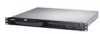
... by one to the server with a Philips (cross) screwdriver just enough to attach the heatsink to its original place. Secure the heat pipe and air duct to completely secure the heatsink. When the mylar is properly installed, the hook as shown below should attach the motherboard edge. ASUS RS100-E6/PI2 2-9 Ensure that the mylar...
... by one to the server with a Philips (cross) screwdriver just enough to attach the heatsink to its original place. Secure the heat pipe and air duct to completely secure the heatsink. When the mylar is properly installed, the hook as shown below should attach the motherboard edge. ASUS RS100-E6/PI2 2-9 Ensure that the mylar...

User Manual
Page 40
2.7.3 Installing ASMB4 series management board (optional) Follow the steps below to the LAN port 3 (dedicated LAN) or LAN port 1 (shared LAN) for server management. Orient and press the ASMB4 management card in place. 3. LAN port 3 LAN port 1 2-22 Chapter 2: Hardware setup Insert the LAN cable plug to install an optional ASMB4 series management board on the motherboard. 2. Locate the BMC_FW1 header on your motherboard. 1.
2.7.3 Installing ASMB4 series management board (optional) Follow the steps below to the LAN port 3 (dedicated LAN) or LAN port 1 (shared LAN) for server management. Orient and press the ASMB4 management card in place. 3. LAN port 3 LAN port 1 2-22 Chapter 2: Hardware setup Insert the LAN cable plug to install an optional ASMB4 series management board on the motherboard. 2. Locate the BMC_FW1 header on your motherboard. 1.

User Manual
Page 41
Rackmount installation Chapter 3 This chapter describes how to install the rackmount rail kit to the barebone server. 2-
Rackmount installation Chapter 3 This chapter describes how to install the rackmount rail kit to the barebone server. 2-

User Manual
Page 42
Pair of rack screws. 3.1 Rackmount rail kit items The rackmount rail kit contains two pairs of rails (one pair for each side of the server system), six (6) pieces of inner rail screws, and two (2) pieces of rack ears 3-2 Chapter 3: Rackmount installation Prepare the bundled pair of rack ears and set of eight (8) screws. Outer rails Inner rails Rack screws Inner rail screws 3.2 Attaching the rack ears The bundled rack ears serve as handle when inserting or pulling the server from a rack cabinet. To attach rack ears: 1.
Pair of rack screws. 3.1 Rackmount rail kit items The rackmount rail kit contains two pairs of rails (one pair for each side of the server system), six (6) pieces of inner rail screws, and two (2) pieces of rack ears 3-2 Chapter 3: Rackmount installation Prepare the bundled pair of rack ears and set of eight (8) screws. Outer rails Inner rails Rack screws Inner rail screws 3.2 Attaching the rack ears The bundled rack ears serve as handle when inserting or pulling the server from a rack cabinet. To attach rack ears: 1.

User Manual
Page 44
... you wish to the corresponding side of the rack cabinet . 7. Secure the outer rail with three inner rail screws. 3. Do the same to install the server. 4. Select one unit of the rack cabinet, then fasten the two screws. 6. Attach the second inner rail to attach the other side of the chassis...
... you wish to the corresponding side of the rack cabinet . 7. Secure the outer rail with three inner rail screws. 3. Do the same to install the server. 4. Select one unit of the rack cabinet, then fasten the two screws. 6. Attach the second inner rail to attach the other side of the chassis...
User Manual
Page 45
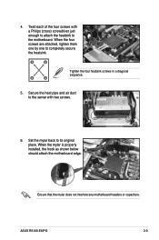
Make sure that the inner rails are properly aligned with the outer rails. Hold the latches, and insert the rear side of the outer rack rail. ASUS RS100-E6/PI2 3-5 Slide the latches on both sides. Firmly hold the server on the inner rack rails to the front end of the server to the direction indicated below. 8.
Make sure that the inner rails are properly aligned with the outer rails. Hold the latches, and insert the rear side of the outer rack rail. ASUS RS100-E6/PI2 3-5 Slide the latches on both sides. Firmly hold the server on the inner rack rails to the front end of the server to the direction indicated below. 8.

User Manual
Page 46
Rack screw 3-6 Chapter 3: Rackmount installation 9. Carefully push the server all the way to the rack with one rack screw at one side. Secure the server to the back until the front panel fits the front end of the rack. 10. Secure the other side as well.
Rack screw 3-6 Chapter 3: Rackmount installation 9. Carefully push the server all the way to the rack with one rack screw at one side. Secure the server to the back until the front panel fits the front end of the rack. 10. Secure the other side as well.
User Manual
Page 57
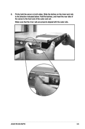
Devices communicate with an SMBus host and/or other SMBus devices using the SMBus interface. ASUS RS100-E6/PI2 4-11 Power Supply SMBus connector (5-pin PSUSMB1) This connector allows you to connect SMBus (System Management Bus) to the power supply unit to read PSU information. 7. BMC header (BMC_FW1) The BMC connector on the motherboard supports an ASUS® Server Management Board 4 Series (ASMB4). 8.
Devices communicate with an SMBus host and/or other SMBus devices using the SMBus interface. ASUS RS100-E6/PI2 4-11 Power Supply SMBus connector (5-pin PSUSMB1) This connector allows you to connect SMBus (System Management Bus) to the power supply unit to read PSU information. 7. BMC header (BMC_FW1) The BMC connector on the motherboard supports an ASUS® Server Management Board 4 Series (ASMB4). 8.

User Manual
Page 67
... the advanced system settings Server For changing the advanced server settings Power For changing the advanced power management (APM) configuration Boot For changing the system boot configuration Tools For configuring options for that particular menu. ASUS RS100-E6/PI2 5-7 Some of a ... differ from one screen to select a field. 5.2.1 BIOS menu screen Menu items Menu bar Configuration fields General help Main Advanced BIOS SETUP UTILITY Server Power Boot Tools Exit System Time [13:44:30] System Date [Tue, 09/22/2009] SATA 1 SATA 2 SATA 3 SATA 4 SATA...
... the advanced system settings Server For changing the advanced server settings Power For changing the advanced power management (APM) configuration Boot For changing the system boot configuration Tools For configuring options for that particular menu. ASUS RS100-E6/PI2 5-7 Some of a ... differ from one screen to select a field. 5.2.1 BIOS menu screen Menu items Menu bar Configuration fields General help Main Advanced BIOS SETUP UTILITY Server Power Boot Tools Exit System Time [13:44:30] System Date [Tue, 09/22/2009] SATA 1 SATA 2 SATA 3 SATA 4 SATA...
