Asus RS100-E8-PI2 Support and Manuals
Get Help and Manuals for this Asus item
View All Support Options Below
Free Asus RS100-E8-PI2 manuals!
Problems with Asus RS100-E8-PI2?
Ask a Question
Free Asus RS100-E8-PI2 manuals!
Problems with Asus RS100-E8-PI2?
Ask a Question
Popular Asus RS100-E8-PI2 Manual Pages
User Guide - Page 13
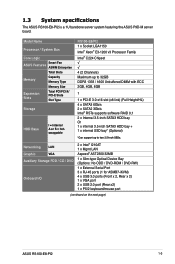
1.3 System specifications
The ASUS RS100-E8-PI2 is a 1U barebone server system featuring the ASUS P9D-M server board. Model Name
Processor / System Bus
Core Logic
ASUS Features
Smart Fan ASWM Enterprise
Total Slots
Memory
Capacity Memory Type
Memory Size
Expansion Slots
Total PCI/PCI-X/ PCI-E Slots
Slot Type
Storage
HDD Bays
I /O
2 x ...
User Guide - Page 15
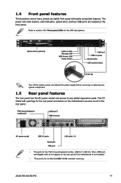
... barebone server has a simple yet stylish front panel with openings for the rear panel connectors on the motherboard are located on the rear panel if the motherboard is not installed.
•... the AC power socket and access to section 1.7.1 Front panel LEDs for an ASUS ASMB7-iKVM controller card only. ASUS RS100-E8-PI2
1-5 PS/2 mouse/keyboard combo port
LAN port 3* USB 3.0 ports
AC power...
User Guide - Page 23
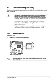
... LGA1150 socket designed for the Intel® Xeon® E3-1200 v3.
• Upon purchase of the PnP cap.
2.2.1 Installing the CPU
To install the CPU: 1. Locate the CPU socket on the socket and the socket contacts are not bent. ASUS RS100-E8-PI2
2-5
Before installing the CPU, ensure that the PnP cap is on the motherboard.
User Guide - Page 29
...notch damage.
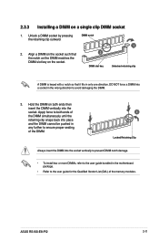
• To install two or more DIMMs, refer to the user guide bundled in the motherboard package.
• Refer to the user guide for the Qualified Vendor List (...Installing a DIMM on the socket.
2
DIMM slot key
1
Unlocked retaining clip
A DIMM is keyed with a notch so that the notch on the DIMM matches the DIMM slot key on a single clip DIMM socket
1.
ASUS RS100-E8-PI2...
User Guide - Page 31

... the bundled set aside.
4. 2.4 Hard disk drives
The server chassis has two HDD bays for installing HDDs to the chassis and set aside. 3....set of bundled screws.
5.
Locate the HDD bay 1 in place. ASUS RS100-E8-PI2
HDD drive tray HDD bay 1
2-13 Prepare a 3.5-inch Serial ATA HDD and the set of screws (as shown). Both HDD bays can support 3.5-inch Serial ATA HDD.
2.4.1 Installing...
User Guide - Page 35
ASUS RS100-E8-PI2
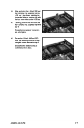
2-17 Secure the 2.5-inch SSD and SSD drive tray assembly to the HDD bay 1 using the screws removed in place.
Carefully place the 2.5-inch SSD ...
User Guide - Page 45
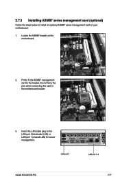
... cable plug to the header. LAN port 3
ASUS RS100-E8-PI2
LAN port 1~2 2-27
Firmly fit the ASMB7 management card to the LAN port 3 (dedicated LAN) or LAN port 1 (shared LAN) for server management. Do not force the pins when connecting the card to the motherboard header.
3. 2.7.3 Installing ASMB7 series management card (optional)
Follow the steps...
User Guide - Page 49

...
5. Find the corresponding 1U space on the front and three at the front and rear of space (1U) on the rack where you wish to the other outer rail. ASUS RS100-E8-PI2
3-3 2. Secure the outer rail with three inner rail screws.
3. Select one unit of the rack cabinet .
7.
Attach the second inner rail to install the server.
4.
User Guide - Page 51
Rack screw
ASUS RS100-E8-PI2
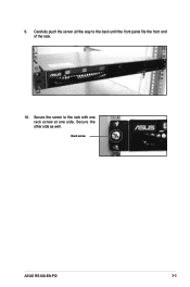
3-5 Secure the other side as well. Secure the server to the back until the front panel fits the front end of the rack.
10.
Carefully push the server all the way to the rack with one rack screw at one side. 9.
User Guide - Page 57
ASUS RS100-E8-PI2
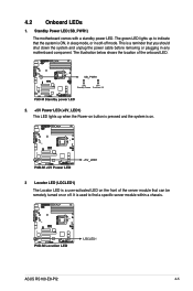
4-5 4.2 Onboard LEDs
1.
The illustration below shows the location of the server module that can be remotely turned on .
3 Locator LED (LOCLED1) The ...LED on the front of the onboard LED.
2. +5V Power LED (+5V_LED1) This LED lights up to find a specific server module within a chassis. The green LED lights up when the Power-on button is pressed and the system is on...
User Guide - Page 123
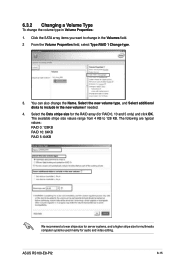
... RAID 5: 64KB
We recommend a lower stripe size for server systems, and a higher stripe size for multimedia computer systems used mainly for RAID 0, 10 and 5 only) and click OK. Select the Data stripe size for the RAID array (for audio and video editing. ASUS RS100-E8-PI2
6-15 Click the SATA array items you want to...
User Guide - Page 131
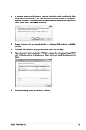
... finishes loading the RAID driver, replace the motherboard Support DVD
with the motherboard Support DVD in the corresponding folder of the RAID controller driver. Select the RAID controller driver you to insert the installation media containing the driver of the Support DVD, and then click OK to continue.
Select the drive to continue.
5. ASUS RS100-E8-PI2
7-5 Click Browse to...
User Guide - Page 135
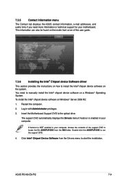
... on Windows® Server 2008 R2:
1.
ASUS RS100-E8-PI2
7-9 Click Intel® Chipset Device Software from the BIN folder.
If Autorun is enabled in your computer. This information can also be found on the inside front cover of the support DVD to locate the file ASSETUP.EXE from the Drivers menu to start the installation. You need more...
User Guide - Page 145
....EXE to locate the file ASSETUP.EXE from the BIN folder. From the License Agreement window, select I accept the terms and click Next.
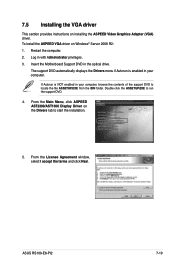
7.5 Installing the VGA driver
This section provides instructions on the Drivers tab to start the installation.
5. ASUS RS100-E8-PI2
7-19 To install the ASPEED VGA driver on Windows® Server 2008 R2: 1. The support DVD automatically displays the...
User Guide - Page 147

... the file ASSETUP.EXE from the BIN folder. Click ASPEED AST2300/AST1300 Display Driver on Windows® Server 2012: 1.
10. If Autorun is enabled in your computer.
Click OK to the optical drive. Log in the Driver Information window. Click OK in with Administrator privileges. 3. ASUS RS100-E8-PI2
7-21 Insert the Motherboard Support DVD to complete the installation.
Asus RS100-E8-PI2 Reviews
We have not received any reviews for Asus yet.