
User Guide
Page 5
...; Server Platform Services 5-24 5.4.12 Onboard LAN Configuration 5-24 5.4.13 Serial Port Console Redirection 5-25 5.4.14 Runtime Error Logging Support 5-27 5.4.15 APM 5-27 5.4.16 Network Stack 5-28 5.4.17 Intel RC Drivers Version Detail 5-28 5.5 Event Logs menu 5-29 5.6 Boot menu 5-30 5.7 Monitor menu 5-33 5.8 Security...5-34 5.9 Tool menu 5-37 5.10 Exit menu 5-37 Chapter 6: RAID configuration 6.1 Setting up RAID 6-2 6.1.1 RAID definitions 6-2 6.1.2 Installing hard disk drives 6-3 6.1.3 Setting Jumpers 6-3 6.1.4 Setting the RAID mode in BIOS 6-3 6.1.5 RAID...
...; Server Platform Services 5-24 5.4.12 Onboard LAN Configuration 5-24 5.4.13 Serial Port Console Redirection 5-25 5.4.14 Runtime Error Logging Support 5-27 5.4.15 APM 5-27 5.4.16 Network Stack 5-28 5.4.17 Intel RC Drivers Version Detail 5-28 5.5 Event Logs menu 5-29 5.6 Boot menu 5-30 5.7 Monitor menu 5-33 5.8 Security...5-34 5.9 Tool menu 5-37 5.10 Exit menu 5-37 Chapter 6: RAID configuration 6.1 Setting up RAID 6-2 6.1.1 RAID definitions 6-2 6.1.2 Installing hard disk drives 6-3 6.1.3 Setting Jumpers 6-3 6.1.4 Setting the RAID mode in BIOS 6-3 6.1.5 RAID...

User Guide
Page 9
... this guide Audience This user guide is intended for setting up, creating and configuring RAID sets using the available utilities. 7. DO NOT throw the motherboard in municipal waste. Chapter 2: Hardware setup This chapter lists the hardware setup procedures that the battery should not be placed in municipal waste. Chapter 6: RAID configuration This chapter provides instructions for system integrators, and experienced users with at least basic knowledge of configuring a server. ix Chapter 5: BIOS information...
... this guide Audience This user guide is intended for setting up, creating and configuring RAID sets using the available utilities. 7. DO NOT throw the motherboard in municipal waste. Chapter 2: Hardware setup This chapter lists the hardware setup procedures that the battery should not be placed in municipal waste. Chapter 6: RAID configuration This chapter provides instructions for system integrators, and experienced users with at least basic knowledge of configuring a server. ix Chapter 5: BIOS information...
User Guide
Page 13
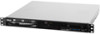
... Smart Fan ASWM Enterprise Total Slots Memory Capacity Memory Type Memory Size Expansion Slots Total PCI/PCI-X/ PCI-E Slots Slot Type Storage HDD Bays I /O 2 x Intel® I210AT 1 x Mgmt LAN Aspeed® AST2300 32MB 1 x Slim-type Optical Device Bay (Options: No ODD / DVD-ROM / DVD-RW) 1 x External Serial Port 3 x RJ-45 ports (1 for ASMB7-iKVM) 4 x USB 3.0 ports (Front x 2, Rear x 2) 1 x VGA port 2 x USB 2.0 port (Rear x2) 1 x PS/2 keyboard/mouse port (continued on the next page) ASUS RS100-E8-PI2 1-3 1.3 System specifications The ASUS RS100-E8-PI2 is a 1U barebone server...
... Smart Fan ASWM Enterprise Total Slots Memory Capacity Memory Type Memory Size Expansion Slots Total PCI/PCI-X/ PCI-E Slots Slot Type Storage HDD Bays I /O 2 x Intel® I210AT 1 x Mgmt LAN Aspeed® AST2300 32MB 1 x Slim-type Optical Device Bay (Options: No ODD / DVD-ROM / DVD-RW) 1 x External Serial Port 3 x RJ-45 ports (1 for ASMB7-iKVM) 4 x USB 3.0 ports (Front x 2, Rear x 2) 1 x VGA port 2 x USB 2.0 port (Rear x2) 1 x PS/2 keyboard/mouse port (continued on the next page) ASUS RS100-E8-PI2 1-3 1.3 System specifications The ASUS RS100-E8-PI2 is a 1U barebone server...
User Guide
Page 15
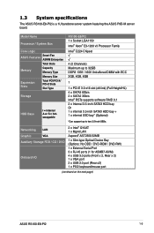
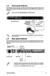
... front panel. PS/2 mouse/keyboard combo port LAN port 3* USB 3.0 ports AC power socket USB 2.0 ports LAN ports 1~2 Serial port VGA port • The ports for the LED descriptions. 1.4 Front panel features This barebone server has a simple yet stylish front panel with openings for the rear panel connectors on the rear panel if the motherboard is not installed. • *This port is for an ASUS ASMB7-iKVM controller card only. The power and reset buttons, LED indicators, optical drive, and two USB ports are also found in the rear panel. ASUS RS100-E8-PI2 1-5
... front panel. PS/2 mouse/keyboard combo port LAN port 3* USB 3.0 ports AC power socket USB 2.0 ports LAN ports 1~2 Serial port VGA port • The ports for the LED descriptions. 1.4 Front panel features This barebone server has a simple yet stylish front panel with openings for the rear panel connectors on the rear panel if the motherboard is not installed. • *This port is for an ASUS ASMB7-iKVM controller card only. The power and reset buttons, LED indicators, optical drive, and two USB ports are also found in the rear panel. ASUS RS100-E8-PI2 1-5

User Guide
Page 17
... or receiving data 2 ON LAN connection is present ON Location switch is normal; Without ASMB7-iKVM installed: CPU over-heated ON 2. indicates no incoming event 1. 1.7 LED information 1.7.1 Front panel LEDs LAN1~2 LED Message LED HDD Access LED Power LED Location LED LED Icon Display status Description Power LED HDD Activity LED Message LED LAN LEDs Location LED ON System power ON OFF No activity Blinking Read/write data activity from the HDD OFF System is pressed. OFF Normal status. (Press the location switch again to turn off.) ASUS RS100-E8-PI2 1-7
... or receiving data 2 ON LAN connection is present ON Location switch is normal; Without ASMB7-iKVM installed: CPU over-heated ON 2. indicates no incoming event 1. 1.7 LED information 1.7.1 Front panel LEDs LAN1~2 LED Message LED HDD Access LED Power LED Location LED LED Icon Display status Description Power LED HDD Activity LED Message LED LAN LEDs Location LED ON System power ON OFF No activity Blinking Read/write data activity from the HDD OFF System is pressed. OFF Normal status. (Press the location switch again to turn off.) ASUS RS100-E8-PI2 1-7

User Guide
Page 28
... Speed 1333/1600 1333/1600 Rank per DIMM Single Rank Dual Rank Single Rank Dual Rank • Always install DIMMs with ECC DDR3 DIMMs into the DIMM sockets using the memory configurations in slots A2 and B2 (Blue). 2-10 Chapter 2: Hardware setup DDR3 modules are developed for better performance with four Double Data Rate 3 (DDR3) Dual Inline Memory Modules (DIMM) sockets. 2.3 System memory 2.3.1 Overview The motherboard comes with less power consumption...
... Speed 1333/1600 1333/1600 Rank per DIMM Single Rank Dual Rank Single Rank Dual Rank • Always install DIMMs with ECC DDR3 DIMMs into the DIMM sockets using the memory configurations in slots A2 and B2 (Blue). 2-10 Chapter 2: Hardware setup DDR3 modules are developed for better performance with four Double Data Rate 3 (DDR3) Dual Inline Memory Modules (DIMM) sockets. 2.3 System memory 2.3.1 Overview The motherboard comes with less power consumption...

User Guide
Page 31
Ensure that secures the HDD drive tray to the chassis and set aside. 4. Remove the HDD drive tray then set aside. 3. ASUS RS100-E8-PI2 HDD drive tray HDD bay 1 2-13 Prepare a 3.5-inch Serial ATA HDD and the set of bundled screws. 5. 2.4 Hard disk drives The server chassis has two HDD bays for installing HDDs to HDD bay 1: 1. Both HDD bays can support 3.5-inch Serial ATA HDD. 2.4.1 Installing a 3.5-inch Serial ATA HDD to HDD...
Ensure that secures the HDD drive tray to the chassis and set aside. 4. Remove the HDD drive tray then set aside. 3. ASUS RS100-E8-PI2 HDD drive tray HDD bay 1 2-13 Prepare a 3.5-inch Serial ATA HDD and the set of bundled screws. 5. 2.4 Hard disk drives The server chassis has two HDD bays for installing HDDs to HDD bay 1: 1. Both HDD bays can support 3.5-inch Serial ATA HDD. 2.4.1 Installing a 3.5-inch Serial ATA HDD to HDD...

User Guide
Page 41
Turn on the BIOS setup. 2. Install the software drivers for information on the system and change any necessary BIOS settings. ASUS RS100-E8-PI2 2-23 See Chapter 5 for the expansion card. Assign an IRQ to the following table. 3. Refer to the card. Standard Interrupt assignments IRQ Priority Standard function 0 1 System Timer 1 2 Keyboard Controller 2 - Programmable Interrupt 3* 11 Communications Port (COM2) 4* 12 Communications Port (COM1) 5* 13 -- 6 14 Floppy Disk Controller 7* 15 -- 8 3 System CMOS/Real Time...
Turn on the BIOS setup. 2. Install the software drivers for information on the system and change any necessary BIOS settings. ASUS RS100-E8-PI2 2-23 See Chapter 5 for the expansion card. Assign an IRQ to the following table. 3. Refer to the card. Standard Interrupt assignments IRQ Priority Standard function 0 1 System Timer 1 2 Keyboard Controller 2 - Programmable Interrupt 3* 11 Communications Port (COM2) 4* 12 Communications Port (COM1) 5* 13 -- 6 14 Floppy Disk Controller 7* 15 -- 8 3 System CMOS/Real Time...

User Guide
Page 63
... card cable connected to light up to 6Gbps of data transfer rate to Serial ATA hard disk drives. ASUS RS100-E8-PI2 4-11 The read or write activities of the Serial ATA hard disks installed. 2. 4.4.2 Internal connectors 1. Hard disk activity LED connector (4-pin HDLED1) This LED connector is for the storage add-on the speed of any device connected to the SATA or SAS add-on card causes the front panel LED to the SATA or SAS add-on card. Serial ATA 6.0/3.0 Gbps connectors • 7-pin SATA 6Gbps_1-4 connector [Light Blue]) • 7-pin SATA 3Gbps_5-6 connector [Black]) Supported...
... card cable connected to light up to 6Gbps of data transfer rate to Serial ATA hard disk drives. ASUS RS100-E8-PI2 4-11 The read or write activities of the Serial ATA hard disks installed. 2. 4.4.2 Internal connectors 1. Hard disk activity LED connector (4-pin HDLED1) This LED connector is for the storage add-on the speed of any device connected to the SATA or SAS add-on card causes the front panel LED to the SATA or SAS add-on card. Serial ATA 6.0/3.0 Gbps connectors • 7-pin SATA 6Gbps_1-4 connector [Light Blue]) • 7-pin SATA 3Gbps_5-6 connector [Black]) Supported...

User Guide
Page 87
... VT-d Capability VT-d Enable NB Card BDAT ACPI Table Support VGA Priority Memory Configuration Haswell 1.3.0.0 Supported [Enabled] [Disabled] [Disabled] [Offboard] Check to enable or disable the Compatible mode. This item allow you to prioritize between onboard and offboard video hardware.Configuration options: [Onboard] [Offboard] ASUS RS100-E8-PI2 5-17 VT-d [Enabled] This allows you set the SATA Mode Selection to [IDE]. Configuration options: [Disabled] [Enabled] Aptio Setup Utility - Compatible Mode [Disabled] This item only appears when you enable or disable VT-d function on...
... VT-d Capability VT-d Enable NB Card BDAT ACPI Table Support VGA Priority Memory Configuration Haswell 1.3.0.0 Supported [Enabled] [Disabled] [Disabled] [Offboard] Check to enable or disable the Compatible mode. This item allow you to prioritize between onboard and offboard video hardware.Configuration options: [Onboard] [Offboard] ASUS RS100-E8-PI2 5-17 VT-d [Enabled] This allows you set the SATA Mode Selection to [IDE]. Configuration options: [Disabled] [Enabled] Aptio Setup Utility - Compatible Mode [Disabled] This item only appears when you enable or disable VT-d function on...

User Guide
Page 89
... all links to L0s State ASUS RS100-E8-PI2 5-19 5.4.5 PCI Subsystem Settings Allows you to change the settings of the PCI Express Devices. Advanced PCI Bus Driver Version V 2.05.02 PCI 64bit Resources Handling Above 4G Decoding [Disabled] PCI Common Settings Load RT32 Image [Enabled] PCI Express Settings PCIE Slot Configuration Change PCI Express Devices Settings. Advanced PCI Express Device Register Setting PCI Express Device Register Settings ASPM Support [Disabled] WARNING: Enabling ASPM may cause some PCIE devices to extend battey life. Aptio Setup Utility...
... all links to L0s State ASUS RS100-E8-PI2 5-19 5.4.5 PCI Subsystem Settings Allows you to change the settings of the PCI Express Devices. Advanced PCI Bus Driver Version V 2.05.02 PCI 64bit Resources Handling Above 4G Decoding [Disabled] PCI Common Settings Load RT32 Image [Enabled] PCI Express Settings PCIE Slot Configuration Change PCI Express Devices Settings. Advanced PCI Express Device Register Setting PCI Express Device Register Settings ASPM Support [Disabled] WARNING: Enabling ASPM may cause some PCIE devices to extend battey life. Aptio Setup Utility...

User Guide
Page 90
Configuration Options: [Disabled][Enabled] 5.4.6 USB Configuration This area allows you to perform PCIE slot configurations. Copyright (C) 2013 American Megatrends, Inc. Advanced USB Configuration USB Devices 1 mouse,2 Hubs Legacy USB Support [Enabled] USB3.0 Support [Enabled] XHCI Hand-off [Enabled] EHCI Hand-off [Disabled] USB Mass Storage Driver Support [Enabled] Port 60/64 Emulation [Enabled] Enables Legacy USB support. Aptio Setup Utility - Copyright (C) 2012 American Megatrends, Inc. AUTO option disables legacy support if no USB device is detected, the item ...
Configuration Options: [Disabled][Enabled] 5.4.6 USB Configuration This area allows you to perform PCIE slot configurations. Copyright (C) 2013 American Megatrends, Inc. Advanced USB Configuration USB Devices 1 mouse,2 Hubs Legacy USB Support [Enabled] USB3.0 Support [Enabled] XHCI Hand-off [Enabled] EHCI Hand-off [Disabled] USB Mass Storage Driver Support [Enabled] Port 60/64 Emulation [Enabled] Enables Legacy USB support. Aptio Setup Utility - Copyright (C) 2012 American Megatrends, Inc. AUTO option disables legacy support if no USB device is detected, the item ...

User Guide
Page 91
...allows you to detect the presence of USB devices at startup. Configuration options: [Auto] [Manual] ASUS RS100-E8-PI2 5-21 If no USB device is detected, the legacy USB support is enabled. This should be enabled for complete USB keyboard legacy support for operating systems without XHCI hand-off support. Configuration options: [Disabled] [Enabled] XHCI Hand-off [Enabled] This setting provides support for legacy USB devices. If detected, the USB controller legacy mode is disabled. Configuration options: [Disabled] [Enabled] USB Mass Storage Driver Support [Enabled] This allows...
...allows you to detect the presence of USB devices at startup. Configuration options: [Auto] [Manual] ASUS RS100-E8-PI2 5-21 If no USB device is detected, the legacy USB support is enabled. This should be enabled for complete USB keyboard legacy support for operating systems without XHCI hand-off support. Configuration options: [Disabled] [Enabled] XHCI Hand-off [Enabled] This setting provides support for legacy USB devices. If detected, the USB controller legacy mode is disabled. Configuration options: [Disabled] [Enabled] USB Mass Storage Driver Support [Enabled] This allows...

User Guide
Page 94
... FW Operation State : M0 without UMA ME FW Error Code : No Error ME NM FW Status Value : 0x80000001 BIOS Booting Mode : Power Optimized Mode Cores Disabled : 0 ME FW SKU Information : Node Manager End-of-POST Status : EOP disabled in POST 5.4.12 Onboard LAN Configuration This area allows you to enable or disable the INTEL I210 LAN function in the system. Aptio Setup Utility - LAN2 Enable [Enabled] Allows you to launch the Intel I210 LAN OpROM. Configuration options: [Disabled] [PXE...
... FW Operation State : M0 without UMA ME FW Error Code : No Error ME NM FW Status Value : 0x80000001 BIOS Booting Mode : Power Optimized Mode Cores Disabled : 0 ME FW SKU Information : Node Manager End-of-POST Status : EOP disabled in POST 5.4.12 Onboard LAN Configuration This area allows you to enable or disable the INTEL I210 LAN function in the system. Aptio Setup Utility - LAN2 Enable [Enabled] Allows you to launch the Intel I210 LAN OpROM. Configuration options: [Disabled] [PXE...

User Guide
Page 97
... a power failure (G3 state). Bits per second [115200] This item only appears when you set the Console Redirection to [Enabled]. Configuration options: [9600] [19200] [38400] [57600] [115200] Flow Control [None] This item only appears when you to [Enabled]. Configuration options: [Power Off] [Power On] [Last State] Power On By PCIE [Disabled] This allows you set the Console Redirection to enable or disable PCIE devices for waking up the system. Configuration options: [Disabled] [Enabled] ASUS RS100-E8-PI2 5-27...
... a power failure (G3 state). Bits per second [115200] This item only appears when you set the Console Redirection to [Enabled]. Configuration options: [9600] [19200] [38400] [57600] [115200] Flow Control [None] This item only appears when you to [Enabled]. Configuration options: [Power Off] [Power On] [Last State] Power On By PCIE [Disabled] This allows you set the Console Redirection to enable or disable PCIE devices for waking up the system. Configuration options: [Disabled] [Enabled] ASUS RS100-E8-PI2 5-27...

User Guide
Page 104
Main Advanced Event Logs Boot Monitor SSeeccuurriittyy Tool Exit Password Description If ONLY the Administrator's password is set, then this is only asked for when entering Setup. From the Enter Current Password box, key in a password, then press . 3. In Setup the User will have Administrator rights. The menu also enables or disables the Secure Boot state and lets the user configure the System Mode state. Aptio Setup Utility - Confirm the password when prompted. The...
Main Advanced Event Logs Boot Monitor SSeeccuurriittyy Tool Exit Password Description If ONLY the Administrator's password is set, then this is only asked for when entering Setup. From the Enter Current Password box, key in a password, then press . 3. In Setup the User will have Administrator rights. The menu also enables or disables the Secure Boot state and lets the user configure the System Mode state. Aptio Setup Utility - Confirm the password when prompted. The...

User Guide
Page 110
... the benefits of data from the support DVD to a floppy disk before you want to boot the system from a hard disk drive included in a created RAID set, copy the RAID driver first from one drive fails, the disk array management software directs all applications to a second drive. This RAID configuration provides data protection and increases fault tolerance to be of RAID 5 configuration include better HDD performance, fault tolerance, and higher storage capacity. RAID 5 stripes both RAID 0 and RAID 1 configurations. Among the...
... the benefits of data from the support DVD to a floppy disk before you want to boot the system from a hard disk drive included in a created RAID set, copy the RAID driver first from one drive fails, the disk array management software directs all applications to a second drive. This RAID configuration provides data protection and increases fault tolerance to be of RAID 5 configuration include better HDD performance, fault tolerance, and higher storage capacity. RAID 5 stripes both RAID 0 and RAID 1 configurations. Among the...

User Guide
Page 111
...the BIOS Setup during POST. 2. Set SATA Mode to the Advanced Menu > SATA Configuration, then press . 3. The P9D-M Series motherboards support Intel® Rapid Storage Technology for Intel® Rapid Storage Technology enterprise Option ROM Utility, set the 3-pin RAID_SEL1 jumper to pins 2-3. You must set the RAID mode in the system user guide. 2. ASUS RS100-E8-PI2 6-3 To do this user manual. 6.1.4 Setting the RAID mode in BIOS You must set the jumper settings of each drive 6.1.3 Setting Jumpers Ensure to turn off power before you can create a RAID set using the utilities...
...the BIOS Setup during POST. 2. Set SATA Mode to the Advanced Menu > SATA Configuration, then press . 3. The P9D-M Series motherboards support Intel® Rapid Storage Technology for Intel® Rapid Storage Technology enterprise Option ROM Utility, set the 3-pin RAID_SEL1 jumper to pins 2-3. You must set the RAID mode in the system user guide. 2. ASUS RS100-E8-PI2 6-3 To do this user manual. 6.1.4 Setting the RAID mode in BIOS You must set the jumper settings of each drive 6.1.3 Setting Jumpers Ensure to turn off power before you can create a RAID set using the utilities...

User Guide
Page 112
... may have set the correct jumper settings of the screen allow you to enter the main menu. 6.2 Intel® Rapid Storage Technology Enterprise Option ROM Utility The Intel® Rapid Storage Technology enterprise Option ROM utility allows you to create RAID 0, RAID 1, RAID 10 (RAID 1+0), and RAID 5 set(s) from Serial ATA hard disk drives that you have installed the Serial ATA hard disk drives, have set the correct SATA mode in the BIOS setup. During POST, press to the Serial ATA connectors supported by...
... may have set the correct jumper settings of the screen allow you to enter the main menu. 6.2 Intel® Rapid Storage Technology Enterprise Option ROM Utility The Intel® Rapid Storage Technology enterprise Option ROM utility allows you to create RAID 0, RAID 1, RAID 10 (RAID 1+0), and RAID 5 set(s) from Serial ATA hard disk drives that you have installed the Serial ATA hard disk drives, have set the correct SATA mode in the BIOS setup. During POST, press to the Serial ATA connectors supported by...

User Guide
Page 140
... need to the optical drive. Insert the Motherboard Support DVD to manually install the LAN controller driver on Windows® Server 2008 R2: 1. If Autorun is enabled in your computer, browse the contents of the support DVD to run the support DVD. 4. From the Intel® Network Connections window, click Install Drivers and Software. 7-14 Chapter 7: Driver installation Double-click the ASSETUP.EXE to locate the file ASSETUP.EXE from the BIN folder. Log in your computer.
... need to the optical drive. Insert the Motherboard Support DVD to manually install the LAN controller driver on Windows® Server 2008 R2: 1. If Autorun is enabled in your computer, browse the contents of the support DVD to run the support DVD. 4. From the Intel® Network Connections window, click Install Drivers and Software. 7-14 Chapter 7: Driver installation Double-click the ASSETUP.EXE to locate the file ASSETUP.EXE from the BIN folder. Log in your computer.


