
User Manual
Page 13
.../s ports Intel® Matrix Storage (for ASMB4-iKVM) 4 x USB 2.0 ports (Front x 2, Rear x 2) 1 x VGA port 1 x PS/2 keyboard port 1 x PS/2 mouse port (continued on the next page) ASUS RS100-E6/PI2 1-3 Supports software RAID 0 & 1 LSI® MegaRAID (for Linux / Windows) - The server supports Intel® LGA1156 Lynnfield / Clarkdale processors, plus other latest technologies through the chipsets...
.../s ports Intel® Matrix Storage (for ASMB4-iKVM) 4 x USB 2.0 ports (Front x 2, Rear x 2) 1 x VGA port 1 x PS/2 keyboard port 1 x PS/2 mouse port (continued on the next page) ASUS RS100-E6/PI2 1-3 Supports software RAID 0 & 1 LSI® MegaRAID (for Linux / Windows) - The server supports Intel® LGA1156 Lynnfield / Clarkdale processors, plus other latest technologies through the chipsets...

User Manual
Page 15
... rear panel if motherboard is not present. • *The port is for the LED descriptions. Refer to section 1.7.1 Front panel LEDs for ASUS ASMB4-iKVM controller card only. ASUS RS100-E6/PI2 1-5 USB 2.0 ports Optical drive HDD Access LED LAN2 LED LAN1 LED Power LED Power button Reset button Turn off the system power and...
... rear panel if motherboard is not present. • *The port is for the LED descriptions. Refer to section 1.7.1 Front panel LEDs for ASUS ASMB4-iKVM controller card only. ASUS RS100-E6/PI2 1-5 USB 2.0 ports Optical drive HDD Access LED LAN2 LED LAN1 LED Power LED Power button Reset button Turn off the system power and...
User Manual
Page 17
... Status Description OFF No link GREEN Linked BLINKING Data activity SPEED LED Status Description OFF 10 Mbps connection ORANGE 100 Mbps connection GREEN 1 Gbps connection ASUS RS100-E6/PI2 1-7
... Status Description OFF No link GREEN Linked BLINKING Data activity SPEED LED Status Description OFF 10 Mbps connection ORANGE 100 Mbps connection GREEN 1 Gbps connection ASUS RS100-E6/PI2 1-7
User Manual
Page 21
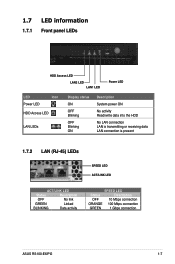
ASUS RS100-E6/PI2 2-3 Slide the cover toward the front until it snaps in place. Position the cover on top of the chassis with the hooks aligned to the side tabs of the chassis. Side tabs 2. 2.1.2 Reinstalling the chassis cover To reinstall the chassis cover: 1.
ASUS RS100-E6/PI2 2-3 Slide the cover toward the front until it snaps in place. Position the cover on top of the chassis with the hooks aligned to the side tabs of the chassis. Side tabs 2. 2.1.2 Reinstalling the chassis cover To reinstall the chassis cover: 1.
User Manual
Page 23
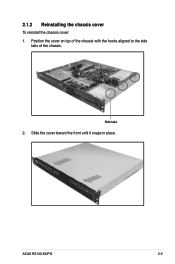
...with the cap on the LGA1156 socket. • The product warranty does not cover damage to the socket contacts resulting from the retention tab. ASUS RS100-E6/PI2 Load lever A B Retention tab 2-5 2.2 Central Processing Unit (CPU) The motherboard comes with your retailer immediately if the PnP cap is .../motherboard components. Press the load lever with a surface mount LGA 1156 Socket designed for the Intel® Lynnfield / Clarkdale series processors. ASUS shoulders the repair cost only if the damage is on the motherboard. 2. To prevent damage to the socket pins, do not remove the...
...with the cap on the LGA1156 socket. • The product warranty does not cover damage to the socket contacts resulting from the retention tab. ASUS RS100-E6/PI2 Load lever A B Retention tab 2-5 2.2 Central Processing Unit (CPU) The motherboard comes with your retailer immediately if the PnP cap is .../motherboard components. Press the load lever with a surface mount LGA 1156 Socket designed for the Intel® Lynnfield / Clarkdale series processors. ASUS shoulders the repair cost only if the damage is on the motherboard. 2. To prevent damage to the socket pins, do not remove the...
User Manual
Page 25
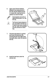
.... If so, skip this step. B A C 8. If it gets into your eyes or touches your skin, wash it . Insert the load lever under the retention lock (C). ASUS RS100-E6/PI2 2-7 The Thermal Interface Material is spread in contact with preapplied thermal paste. DO NOT eat it off immediately, and seek professional medical help. 7. Apply some...
.... If so, skip this step. B A C 8. If it gets into your eyes or touches your skin, wash it . Insert the load lever under the retention lock (C). ASUS RS100-E6/PI2 2-7 The Thermal Interface Material is spread in contact with preapplied thermal paste. DO NOT eat it off immediately, and seek professional medical help. 7. Apply some...
User Manual
Page 27
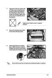
A B B A Tighten the four heatsink screws in a diagonal sequence. 5. When the mylar is properly installed, the hook as shown below should attach the motherboard edge. ASUS RS100-E6/PI2 2-9 When the four screws are attached, tighten them one by one to the server with a Philips (cross) screwdriver just enough to attach the heatsink to ...
A B B A Tighten the four heatsink screws in a diagonal sequence. 5. When the mylar is properly installed, the hook as shown below should attach the motherboard edge. ASUS RS100-E6/PI2 2-9 When the four screws are attached, tighten them one by one to the server with a Philips (cross) screwdriver just enough to attach the heatsink to ...
User Manual
Page 29
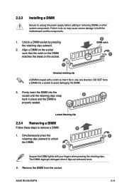
... with your fingers when pressing the retaining clips. DO NOT force a DIMM into the socket until the retaining clips snap 3 back in only one direction. ASUS RS100-E6/PI2 2-11 Simultaneously press the 1 retaining clips outward to avoid damaging the DIMM. 3. Failure to do so may cause severe damage to both the motherboard and...
... with your fingers when pressing the retaining clips. DO NOT force a DIMM into the socket until the retaining clips snap 3 back in only one direction. ASUS RS100-E6/PI2 2-11 Simultaneously press the 1 retaining clips outward to avoid damaging the DIMM. 3. Failure to do so may cause severe damage to both the motherboard and...

User Manual
Page 31
Remove the four screws to the HDD tray 2. HDD bracket ASUS RS100-E6/PI2 2-13 4. If you have an ODD installed, remove the ODD first before installing a hard disk drive to release the HDD bracket under the optical disk drive. Secure the hard disk drive with four screws. 2.4.2 Installing a hard disk drive to the HDD tray 2 To install a hard disk drive to remove the two screws as shown. 2. Disconnect the ODD cable, and then use a screwdriver to the HDD tray 2: 1.
Remove the four screws to the HDD tray 2. HDD bracket ASUS RS100-E6/PI2 2-13 4. If you have an ODD installed, remove the ODD first before installing a hard disk drive to release the HDD bracket under the optical disk drive. Secure the hard disk drive with four screws. 2.4.2 Installing a hard disk drive to the HDD tray 2 To install a hard disk drive to remove the two screws as shown. 2. Disconnect the ODD cable, and then use a screwdriver to the HDD tray 2: 1.
User Manual
Page 33
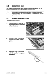
... damage to unplug the power cord before installing or removing an expansion card. Remove the screw to release the metal slot cover from the system. 3. ASUS RS100-E6/PI2 2-15 Hold the riser card and pull it from the PCI Express slot on the motherboard. 2. You need to remove the riser card and the...
... damage to unplug the power cord before installing or removing an expansion card. Remove the screw to release the metal slot cover from the system. 3. ASUS RS100-E6/PI2 2-15 Hold the riser card and pull it from the PCI Express slot on the motherboard. 2. You need to remove the riser card and the...

User Manual
Page 35
.../2 Compatible Mouse Port 13 8 Numeric Data Processor 14* 9 Primary IDE Channel 15* 10 Secondary IDE Channel * These IRQs are usually available for the expansion card. ASUS RS100-E6/PI2 2-17 2.5.2 Configuring an expansion card After installing the expansion card, configure the it by adjusting the software settings. 1. See Chapter 5 for information on the system...
.../2 Compatible Mouse Port 13 8 Numeric Data Processor 14* 9 Primary IDE Channel 15* 10 Secondary IDE Channel * These IRQs are usually available for the expansion card. ASUS RS100-E6/PI2 2-17 2.5.2 Configuring an expansion card After installing the expansion card, configure the it by adjusting the software settings. 1. See Chapter 5 for information on the system...
User Manual
Page 37
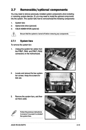
... before removing any components. 2.7.1 System fans To remove the system fan: 1. Locate and remove the two system fan screws. Keep the screws for late use. 3. ASUS RS100-E6/PI2 2-19 This section tells how to reinstall the system fans. Remove the system fans, and then set them aside. Unplug the system fan cables from...
... before removing any components. 2.7.1 System fans To remove the system fan: 1. Locate and remove the two system fan screws. Keep the screws for late use. 3. ASUS RS100-E6/PI2 2-19 This section tells how to reinstall the system fans. Remove the system fans, and then set them aside. Unplug the system fan cables from...
User Manual
Page 39
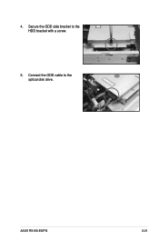
Connect the ODD cable to the HDD bracket with a screw. 5. ASUS RS100-E6/PI2 2-21 4. Secure the ODD side bracket to the optical disk drive.
Connect the ODD cable to the HDD bracket with a screw. 5. ASUS RS100-E6/PI2 2-21 4. Secure the ODD side bracket to the optical disk drive.
User Manual
Page 43
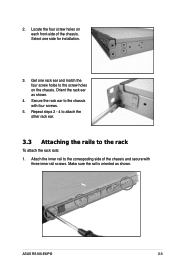
Secure the rack ear to the rack To attach the rack rails: 1. ASUS RS100-E6/PI2 3-3 Orient the rack ear as shown. Repeat steps 2 - 4 to attach the other rack ear. 3.3 Attaching the rails to the chassis with three inner rail screws. Attach the inner rail to the screw holes on each front-side of the chassis and secure with four screws. 5. Locate the four screw holes on the chassis. Get one side for installation. 3. Select one rack ear and match the four screw holes to the correspoding side of the chassis. Make sure the rail is oriented as shown. 4. 2.
Secure the rack ear to the rack To attach the rack rails: 1. ASUS RS100-E6/PI2 3-3 Orient the rack ear as shown. Repeat steps 2 - 4 to attach the other rack ear. 3.3 Attaching the rails to the chassis with three inner rail screws. Attach the inner rail to the screw holes on each front-side of the chassis and secure with four screws. 5. Locate the four screw holes on the chassis. Get one side for installation. 3. Select one rack ear and match the four screw holes to the correspoding side of the chassis. Make sure the rail is oriented as shown. 4. 2.
User Manual
Page 45
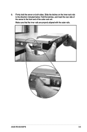
8. Hold the latches, and insert the rear side of the server to the direction indicated below. Firmly hold the server on the inner rack rails to the front end of the outer rack rail. Make sure that the inner rails are properly aligned with the outer rails. Slide the latches on both sides. ASUS RS100-E6/PI2 3-5
8. Hold the latches, and insert the rear side of the server to the direction indicated below. Firmly hold the server on the inner rack rails to the front end of the outer rack rail. Make sure that the inner rails are properly aligned with the outer rails. Slide the latches on both sides. ASUS RS100-E6/PI2 3-5
User Manual
Page 49
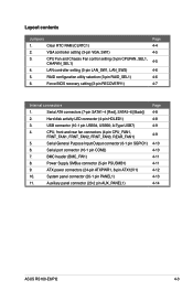
... ATX12V1) 10. Serial port connector (10-1 pin COM2) 7. BMC header (BMC_FW1) 8. Auxiliary panel connector (20-2 pin AUX_PANEL1) Page 4-8 4-8 4-9 4-9 4-10 4-10 4-11 4-11 4-12 4-13 4-14 ASUS RS100-E6/PI2 4-3 Serial ATA connectors (7-pin SATA1-4 [Red], SATA5-6 [Black]) 2. Hard disk activity LED connector (4-pin HDLED1) 3. CPU, front and rear fan connectors (4-pin CPU_FAN1, FRNT_FAN1, FRNT_FAN2...
... ATX12V1) 10. Serial port connector (10-1 pin COM2) 7. BMC header (BMC_FW1) 8. Auxiliary panel connector (20-2 pin AUX_PANEL1) Page 4-8 4-8 4-9 4-9 4-10 4-10 4-11 4-11 4-12 4-13 4-14 ASUS RS100-E6/PI2 4-3 Serial ATA connectors (7-pin SATA1-4 [Red], SATA5-6 [Black]) 2. Hard disk activity LED connector (4-pin HDLED1) 3. CPU, front and rear fan connectors (4-pin CPU_FAN1, FRNT_FAN1, FRNT_FAN2...
User Manual
Page 51
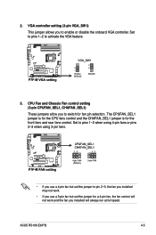
... setting (3-pin VGA_SW1) This jumper allows you installed will always run at full speed. Set to pins 1-2 to enable or disable the onboard VGA controller. ASUS RS100-E6/PI2 4-5 Set to pins 1-2 when using 4-pin fans or pins 2-3 when using 3-pin fans. • If you use a 4-pin fan but set the jumper to switch...
... setting (3-pin VGA_SW1) This jumper allows you installed will always run at full speed. Set to pins 1-2 to enable or disable the onboard VGA controller. ASUS RS100-E6/PI2 4-5 Set to pins 1-2 when using 4-pin fans or pins 2-3 when using 3-pin fans. • If you use a 4-pin fan but set the jumper to switch...
User Manual
Page 53
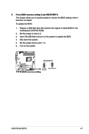
Set the jumper to pins 1-2. 6. Set the jumper back to pins 2-3. 3. Shut down the system. 5. Turn on the system to quickly update or recover the BIOS settings when it becomes corrupted. Insert the USB flash and turn on the system. ASUS RS100-E6/PI2 4-7 Prepare a USB flash disk that contains the original or latest BIOS for the motherboard (XXXXXX.ROM). 2. 6. Force BIOS recovery setting (3-pin RECOVERY1) This jumper allows you to update the BIOS. 4. To update the BIOS: 1.
Set the jumper to pins 1-2. 6. Set the jumper back to pins 2-3. 3. Shut down the system. 5. Turn on the system to quickly update or recover the BIOS settings when it becomes corrupted. Insert the USB flash and turn on the system. ASUS RS100-E6/PI2 4-7 Prepare a USB flash disk that contains the original or latest BIOS for the motherboard (XXXXXX.ROM). 2. 6. Force BIOS recovery setting (3-pin RECOVERY1) This jumper allows you to update the BIOS. 4. To update the BIOS: 1.
User Manual
Page 55
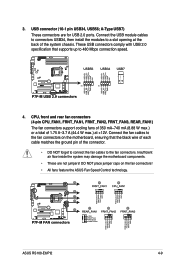
... place jumper caps on the motherboard, ensuring that supports up to the fan connectors on the fan connectors! • All fans feature the ASUS Fan Speed Control technology. ASUS RS100-E6/PI2 4-9 Connect the USB module cables to connectors USB34, then install the modules to the fan connectors. Insufficient air flow inside the system may...
... place jumper caps on the motherboard, ensuring that supports up to the fan connectors on the fan connectors! • All fans feature the ASUS Fan Speed Control technology. ASUS RS100-E6/PI2 4-9 Connect the USB module cables to connectors USB34, then install the modules to the fan connectors. Insufficient air flow inside the system may...
User Manual
Page 57
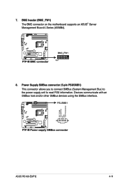
ASUS RS100-E6/PI2 4-11 BMC header (BMC_FW1) The BMC connector on the motherboard supports an ASUS® Server Management Board 4 Series (ASMB4). 8. 7. Devices communicate with an SMBus host and/or other SMBus devices using the SMBus interface. Power Supply SMBus connector (5-pin PSUSMB1) This connector allows you to connect SMBus (System Management Bus) to the power supply unit to read PSU information.
ASUS RS100-E6/PI2 4-11 BMC header (BMC_FW1) The BMC connector on the motherboard supports an ASUS® Server Management Board 4 Series (ASMB4). 8. 7. Devices communicate with an SMBus host and/or other SMBus devices using the SMBus interface. Power Supply SMBus connector (5-pin PSUSMB1) This connector allows you to connect SMBus (System Management Bus) to the power supply unit to read PSU information.


