
User Manual
Page 3
Contents Contents...iii Notices...vii Safety information viii About this guide ix Chapter 1: Product introduction 1.1 System package contents 1-2 1.2 Serial number label 1-2 1.3 System specifications 1-3 1.4 Front panel features 1-5 1.5 Rear panel features 1-5 1.6 Internal features 1-6 1.7 LED information 1-7 1.7.1 Front panel LEDs 1-7 1.7.2 LAN (RJ-45) LEDs 1-7 Chapter 2: Hardware setup 2.1 Chassis cover 2-2 2.1.1 Removing the chassis cover 2-2 2.1.2 Reinstalling the chassis cover 2-3 2.2 Central...
Contents Contents...iii Notices...vii Safety information viii About this guide ix Chapter 1: Product introduction 1.1 System package contents 1-2 1.2 Serial number label 1-2 1.3 System specifications 1-3 1.4 Front panel features 1-5 1.5 Rear panel features 1-5 1.6 Internal features 1-6 1.7 LED information 1-7 1.7.1 Front panel LEDs 1-7 1.7.2 LAN (RJ-45) LEDs 1-7 Chapter 2: Hardware setup 2.1 Chassis cover 2-2 2.1.1 Removing the chassis cover 2-2 2.1.2 Reinstalling the chassis cover 2-3 2.2 Central...

User Manual
Page 9
... knowledge of electronic products. This product has been designed to perform when installing or removing system components. 3. Chapter 1: Product Introduction This chapter describes the general features of parts and recycling. Chapter 4: Motherboard information This chapter includes the motherboard layout and brief descriptions of the crossed out wheeled bin indicates that the...
... knowledge of electronic products. This product has been designed to perform when installing or removing system components. 3. Chapter 1: Product Introduction This chapter describes the general features of parts and recycling. Chapter 4: Motherboard information This chapter includes the motherboard layout and brief descriptions of the crossed out wheeled bin indicates that the...

User Manual
Page 11
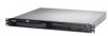
Product introduction Chapter 1 This chapter describes the general features of the server, including sections on front panel and rear panel specifications.
Product introduction Chapter 1 This chapter describes the general features of the server, including sections on front panel and rear panel specifications.

User Manual
Page 13
... (for ASMB4-iKVM) 4 x USB 2.0 ports (Front x 2, Rear x 2) 1 x VGA port 1 x PS/2 keyboard port 1 x PS/2 mouse port (continued on the next page) ASUS RS100-E6/PI2 1-3 1.3 System specifications The ASUS RS100-E6/PI2 is a 1U barebone server system featuring the ASUS P7F-M server board. Supports software RAID 0 & 1 2 x Internal 3.5" SATA2 HDD Bays 2 x Intel® 82574L + 1 x Mgmt LAN Aspeed® AST2050 8MB 1 x Slim-type...
... (for ASMB4-iKVM) 4 x USB 2.0 ports (Front x 2, Rear x 2) 1 x VGA port 1 x PS/2 keyboard port 1 x PS/2 mouse port (continued on the next page) ASUS RS100-E6/PI2 1-3 1.3 System specifications The ASUS RS100-E6/PI2 is a 1U barebone server system featuring the ASUS P7F-M server board. Supports software RAID 0 & 1 2 x Internal 3.5" SATA2 HDD Bays 2 x Intel® 82574L + 1 x Mgmt LAN Aspeed® AST2050 8MB 1 x Slim-type...

User Manual
Page 15
The I/O shield with easily accessible features. ASUS RS100-E6/PI2 1-5 1.4 Front panel features The barebone server displays a simple yet stylish front panel with openings for ASUS ASMB4-iKVM controller card only. USB 2.0 ports Optical drive HDD Access LED LAN2 LED LAN1 LED Power LED Power button Reset button Turn off the ...
The I/O shield with easily accessible features. ASUS RS100-E6/PI2 1-5 1.4 Front panel features The barebone server displays a simple yet stylish front panel with openings for ASUS ASMB4-iKVM controller card only. USB 2.0 ports Optical drive HDD Access LED LAN2 LED LAN1 LED Power LED Power button Reset button Turn off the ...

User Manual
Page 16
1.6 Internal features The barebone server includes the basic components as shown. 1 3 4 5 6 2 1. HDD Tray 1 Turn off the system power and detach the power supply before removing or replacing .... *WARNING HAZARDOUS MOVING PARTS KEEP FINGERS AND OTHER BODY PARTS AWAY 1-6 Chapter 1: Product introduction The barebone server does not include a floppy disk drive. Power Supply 5. ASUS P7F-M Server Board 4. System Fan (x2) (9GV0412P3J051) 3. PCI Express x16 Riser Card (at x16 link) 2. Connect a USB floppy disk drive to any system component. HDD...
1.6 Internal features The barebone server includes the basic components as shown. 1 3 4 5 6 2 1. HDD Tray 1 Turn off the system power and detach the power supply before removing or replacing .... *WARNING HAZARDOUS MOVING PARTS KEEP FINGERS AND OTHER BODY PARTS AWAY 1-6 Chapter 1: Product introduction The barebone server does not include a floppy disk drive. Power Supply 5. ASUS P7F-M Server Board 4. System Fan (x2) (9GV0412P3J051) 3. PCI Express x16 Riser Card (at x16 link) 2. Connect a USB floppy disk drive to any system component. HDD...
User Manual
Page 51
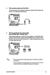
The CPUFAN_SEL1 jumper is for the CPU fans control and the CHAFAN_SEL1 jumper is for fan pin selection. ASUS RS100-E6/PI2 4-5 CPU Fan and Chassis Fan control setting (3-pin CPUFAN_SEL1, CHAFAN_SEL1) These jumpers allow you to pin 2-3, the fan you installed may not work. • If ... always run at full speed. Set to pins 1-2 when using 4-pin fans or pins 2-3 when using 3-pin fans. • If you to activate the VGA feature. 3. 2. VGA controller setting (3-pin VGA_SW1) This jumper allows you use a 4-pin fan but set the jumper to switch for the front fans and rear fans...
The CPUFAN_SEL1 jumper is for the CPU fans control and the CHAFAN_SEL1 jumper is for fan pin selection. ASUS RS100-E6/PI2 4-5 CPU Fan and Chassis Fan control setting (3-pin CPUFAN_SEL1, CHAFAN_SEL1) These jumpers allow you to pin 2-3, the fan you installed may not work. • If ... always run at full speed. Set to pins 1-2 when using 4-pin fans or pins 2-3 when using 3-pin fans. • If you to activate the VGA feature. 3. 2. VGA controller setting (3-pin VGA_SW1) This jumper allows you use a 4-pin fan but set the jumper to switch for the front fans and rear fans...

User Manual
Page 52
... enable or disable the onboard Intel® Intel 82574LGigabit LAN controllers. Place the jumper caps over pins 1-2 if you want to activate the Gigabit LAN feature. 5. 4.
... enable or disable the onboard Intel® Intel 82574LGigabit LAN controllers. Place the jumper caps over pins 1-2 if you want to activate the Gigabit LAN feature. 5. 4.
User Manual
Page 55
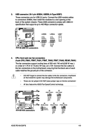
... motherboard, ensuring that supports up to the fan connectors. ASUS RS100-E6/PI2 4-9 Connect the USB module cables to connectors USB34, then install the modules to a slot opening at +12V. Connect the fan cables to the fan connectors on the fan connectors! • All fans feature the ASUS Fan Speed Control technology. A-Type USB7) These connectors...
... motherboard, ensuring that supports up to the fan connectors. ASUS RS100-E6/PI2 4-9 Connect the USB module cables to connectors USB34, then install the modules to a slot opening at +12V. Connect the fan cables to the fan connectors on the fan connectors! • All fans feature the ASUS Fan Speed Control technology. A-Type USB7) These connectors...

User Manual
Page 60
...setting is for the locator button on the front panel. LAN activity LED (2-pin LAN1_LED, LAN2_LED) These leads are for additional front panel features including front panel SMB, locator LED and switch, chassis intrusion, and LAN LEDs. 1. Locator LED (2-pin LOCATORLED1 and 2-pin LOCATORLED2) These... leads are for the intrusion detection feature for the locator LED1 and LED2 on the front panel. Chassis intrusion (4-1 pin CHASSIS) These leads are for chassis with intrusion sensor ...
...setting is for the locator button on the front panel. LAN activity LED (2-pin LAN1_LED, LAN2_LED) These leads are for additional front panel features including front panel SMB, locator LED and switch, chassis intrusion, and LAN LEDs. 1. Locator LED (2-pin LOCATORLED1 and 2-pin LOCATORLED2) These... leads are for the intrusion detection feature for the locator LED1 and LED2 on the front panel. Chassis intrusion (4-1 pin CHASSIS) These leads are for chassis with intrusion sensor ...

User Manual
Page 62
... corrupted.) Refer to enable EZ Flash 2. Copy the original motherboard BIOS using this utility, download the latest BIOS from the ASUS website at www.asus.com. Or, press + during the POST to the corresponding sections for details on these utilities. To update the BIOS using... a bootable USB flash disk drive.) 3. BUPDATER utility (Updates the BIOS in case you start using the ASUS Update or AFUDOS utilities. 5.1.1 ASUS EZ Flash 2 utility The ASUS EZ Flash 2 feature allows you to manage and update the motherboard Basic Input/Output System (BIOS) setup: 1. 5.1 Managing and...
... corrupted.) Refer to enable EZ Flash 2. Copy the original motherboard BIOS using this utility, download the latest BIOS from the ASUS website at www.asus.com. Or, press + during the POST to the corresponding sections for details on these utilities. To update the BIOS using... a bootable USB flash disk drive.) 3. BUPDATER utility (Updates the BIOS in case you start using the ASUS Update or AFUDOS utilities. 5.1.1 ASUS EZ Flash 2 utility The ASUS EZ Flash 2 feature allows you to manage and update the motherboard Basic Input/Output System (BIOS) setup: 1. 5.1 Managing and...

User Manual
Page 66
...RAM of your system using the provided utility described in section 5.1 Managing and updating your BIOS. If you can enable the security password feature or change the configuration of the firmware chip. Select the Load Default Settings item under the Exit Menu. Use the BIOS Setup program... Menu. • The BIOS setup screens shown in the future. This section explains how to configure your screen. • Visit the ASUS website at www.asus.com to download the latest BIOS file for this motherboard apply for this motherboard. 5-6 Chapter 5: BIOS setup This requires you see on...
...RAM of your system using the provided utility described in section 5.1 Managing and updating your BIOS. If you can enable the security password feature or change the configuration of the firmware chip. Select the Load Default Settings item under the Exit Menu. Use the BIOS Setup program... Menu. • The BIOS setup screens shown in the future. This section explains how to configure your screen. • Visit the ASUS website at www.asus.com to download the latest BIOS file for this motherboard apply for this motherboard. 5-6 Chapter 5: BIOS setup This requires you see on...

User Manual
Page 70
... system. When set to [Auto], the data transfer from and to the device occurs one sector at a time if the device supports multi-sector transfer feature. Configuration options: [Auto] [SWDMA0] [SWDMA1] [SWDMA2] [MWDMA0] [MWDMA1] [MWDMA2] [UDMA0] [UDMA1] [UDMA2] [UDMA3] [UDMA4] [UDMA5] SMART Monitoring [Auto] Sets the Smart Monitoring, Analysis, and Reporting...
... system. When set to [Auto], the data transfer from and to the device occurs one sector at a time if the device supports multi-sector transfer feature. Configuration options: [Auto] [SWDMA0] [SWDMA1] [SWDMA2] [MWDMA0] [MWDMA1] [MWDMA2] [UDMA0] [UDMA1] [UDMA2] [UDMA3] [UDMA4] [UDMA5] SMART Monitoring [Auto] Sets the Smart Monitoring, Analysis, and Reporting...

User Manual
Page 71
... enables device write protection. The AHCI allows the onboard storage driver to enable advanced Serial ATA features that increases storage performance on random workloads by the Southbridge chip. Configuration options: [0] [5] [10] [15] [20] [25] [30] [35] ASUS RS100-E6/PI2 5-11 Change Option F1 General Help F10 Save and Exit ESC Exit v02.61 (C)Copyright...
... enables device write protection. The AHCI allows the onboard storage driver to enable advanced Serial ATA features that increases storage performance on random workloads by the Southbridge chip. Configuration options: [0] [5] [10] [15] [20] [25] [30] [35] ASUS RS100-E6/PI2 5-11 Change Option F1 General Help F10 Save and Exit ESC Exit v02.61 (C)Copyright...

User Manual
Page 76
...-Threading Technology function. When disabled, only one thread per activated core is controlled by the operating system. Enable this item to [Disabled] forces the XD feature flag to always return to [Disabled], the CPU runs at its default speed.
...-Threading Technology function. When disabled, only one thread per activated core is controlled by the operating system. Enable this item to [Disabled] forces the XD feature flag to always return to [Disabled], the CPU runs at its default speed.

User Manual
Page 78
... Timing by SPD [EAnuatbol]ed] DRAM Margin Ranks [Disabled] MReCmoSreyriFarleqDuebnucgy Messa ge Level [DAiustaob]led] Memory Mode [Independent] Demand Scrubbing [Disabled] MPeamtorroyl ESCcCruFbubnicntgi on ASUS website at www.asus.com. 5-18 Chapter 5: BIOS setup Configure North Bridge features. Memory Remap Feature [Enabled] Setting this item to [Enabled] allows you to change advanced chipset settings.
... Timing by SPD [EAnuatbol]ed] DRAM Margin Ranks [Disabled] MReCmoSreyriFarleqDuebnucgy Messa ge Level [DAiustaob]led] Memory Mode [Independent] Demand Scrubbing [Disabled] MPeamtorroyl ESCcCruFbubnicntgi on ASUS website at www.asus.com. 5-18 Chapter 5: BIOS setup Configure North Bridge features. Memory Remap Feature [Enabled] Setting this item to [Enabled] allows you to change advanced chipset settings.

User Manual
Page 84
...] [Enabled] 5-24 Chapter 5: BIOS setup APIC ACPI SCI IRQ [Disabled] Allows you to enable or disable the APIC ACPI SCI IRQ feature. Configuration options: [Disabled] [Enabled] HPET Memory Address [FED00000h] Configuration options: [FED00000h] [FED01000h] [FED02000h] [FED03000h] General WHEA Configuration...Hardware Error Architecture. Chipset ACPI Configuration Advanced BIOS SETUP UTILITY South Bridge ACPI Configuration Energy Lake Feature APIC ACPI SCI IRQ High Performance Event Timer HPET Memory Address [Disabled] [Disabled] [Disabled] [FED00000h] Options Enabled Disabled...
...] [Enabled] 5-24 Chapter 5: BIOS setup APIC ACPI SCI IRQ [Disabled] Allows you to enable or disable the APIC ACPI SCI IRQ feature. Configuration options: [Disabled] [Enabled] HPET Memory Address [FED00000h] Configuration options: [FED00000h] [FED01000h] [FED02000h] [FED03000h] General WHEA Configuration...Hardware Error Architecture. Chipset ACPI Configuration Advanced BIOS SETUP UTILITY South Bridge ACPI Configuration Energy Lake Feature APIC ACPI SCI IRQ High Performance Event Timer HPET Memory Address [Disabled] [Disabled] [Disabled] [FED00000h] Options Enabled Disabled...

User Manual
Page 86
Remote Access Configuration The items in this menu allows you to customize the server features. Configuration options: [Disabled] [Enabled] The following items appear only when Remote Access is not user-configurable and changes with the configuration ...3] This item is set to [Enabled]. 5.5 Server menu The Server menu items allow you to configure the Remote Access features. Remote Access [Enabled] Enables or disables the remote access feature. Configuration options: [COM1] [COM2] Base Address. Main Advanced Server BIOS SETUP UTILITY Power Boot Tools Exit Remote Access ...
Remote Access Configuration The items in this menu allows you to customize the server features. Configuration options: [Disabled] [Enabled] The following items appear only when Remote Access is not user-configurable and changes with the configuration ...3] This item is set to [Enabled]. 5.5 Server menu The Server menu items allow you to configure the Remote Access features. Remote Access [Enabled] Enables or disables the remote access feature. Configuration options: [COM1] [COM2] Base Address. Main Advanced Server BIOS SETUP UTILITY Power Boot Tools Exit Remote Access ...

User Manual
Page 89
... By External Modems [Disabled] [Disabled] Disables to make the selection. Power On By PCI Devices [Disabled] [Disabled] Disables the PME to configure alarm time. This feature requires an ATX power supply that turns the system power on the first try. ASUS RS100-E6/PI2 5-29 Use the or key to wake up event.
... By External Modems [Disabled] [Disabled] Disables to make the selection. Power On By PCI Devices [Disabled] [Disabled] Disables the PME to configure alarm time. This feature requires an ATX power supply that turns the system power on the first try. ASUS RS100-E6/PI2 5-29 Use the or key to wake up event.

User Manual
Page 90
... the detected temperatures. Configuration options: [Full Speed Mode] [High Density Mode] [Generic Mode] [Whisper Mode] The default setting for the RS100-E6/PI2 server is not connected to configure the ASUS Smart Fan feature that smartly adjusts the fan speeds for more efficient system operation. CPU1/MB1/TR1 Temperature [xxxºC/xxxºF] The onboard...
... the detected temperatures. Configuration options: [Full Speed Mode] [High Density Mode] [Generic Mode] [Whisper Mode] The default setting for the RS100-E6/PI2 server is not connected to configure the ASUS Smart Fan feature that smartly adjusts the fan speeds for more efficient system operation. CPU1/MB1/TR1 Temperature [xxxºC/xxxºF] The onboard...