
User Manual
Page 3
... 1-7 1.7.1 Front panel LEDs 1-7 1.7.2 LAN (RJ-45) LEDs 1-7 Chapter 2: Hardware setup 2.1 Chassis cover 2-2 2.1.1 Removing the chassis cover 2-2 2.1.2 Reinstalling the chassis cover 2-3 2.2 Central Processing Unit (CPU 2-5 2.2.1 Installing the CPU 2-5 2.2.2 Installing the CPU heatsink and airduct 2-8 2.3 System memory 2-10 2.3.1 Overview 2-10 2.3.2 Memory Configurations 2-10 2.3.3 Installing a DIMM 2-11 2.3.4 Removing a DIMM 2-11 2.4 Hard disk drives 2-12 2.4.1 Installing a hard...
... 1-7 1.7.1 Front panel LEDs 1-7 1.7.2 LAN (RJ-45) LEDs 1-7 Chapter 2: Hardware setup 2.1 Chassis cover 2-2 2.1.1 Removing the chassis cover 2-2 2.1.2 Reinstalling the chassis cover 2-3 2.2 Central Processing Unit (CPU 2-5 2.2.1 Installing the CPU 2-5 2.2.2 Installing the CPU heatsink and airduct 2-8 2.3 System memory 2-10 2.3.1 Overview 2-10 2.3.2 Memory Configurations 2-10 2.3.3 Installing a DIMM 2-11 2.3.4 Removing a DIMM 2-11 2.4 Hard disk drives 2-12 2.4.1 Installing a hard...

User Manual
Page 4
...the rack 3-3 Chapter 4: Motherboard Info 4.1 Motherboard layout 4-2 4.2 Jumpers 4-4 4.3 Internal connectors 4-8 Chapter 5: BIOS setup 5.1 Managing and updating your BIOS 5-2 5.1.1 ASUS EZ Flash 2 utility 5-2 5.1.2 BUPDATER utility 5-3 5.1.3 ASUS CrashFree BIOS 3 utility 5-5 5.2 BIOS setup program 5-6 5.2.1 BIOS menu screen 5-7 5.2.2 Menu bar 5-7 5.2.3 Navigation keys 5-7 5.2.4 Menu items 5-8 5.2.5 Sub-... 5-9 5.3.3 SATA1-6 5-9 5.3.4 Storage Configuration 5-11 5.3.5 AHCI Configuration 5-12 5.3.6 System Information 5-13 5.4 Advanced menu 5-14 5.4.1 CPU Configuration 5-14 iv
...the rack 3-3 Chapter 4: Motherboard Info 4.1 Motherboard layout 4-2 4.2 Jumpers 4-4 4.3 Internal connectors 4-8 Chapter 5: BIOS setup 5.1 Managing and updating your BIOS 5-2 5.1.1 ASUS EZ Flash 2 utility 5-2 5.1.2 BUPDATER utility 5-3 5.1.3 ASUS CrashFree BIOS 3 utility 5-5 5.2 BIOS setup program 5-6 5.2.1 BIOS menu screen 5-7 5.2.2 Menu bar 5-7 5.2.3 Navigation keys 5-7 5.2.4 Menu items 5-8 5.2.5 Sub-... 5-9 5.3.3 SATA1-6 5-9 5.3.4 Storage Configuration 5-11 5.3.5 AHCI Configuration 5-12 5.3.6 System Information 5-13 5.4 Advanced menu 5-14 5.4.1 CPU Configuration 5-14 iv

User Manual
Page 12
... I/O Board (FPB-R9) 1 x USB Board (USB-R9) 2 x System Fans (40mm x 28mm) Accessories 1 x RS100-E6/PI2 User's Guide 1 x ASUS ASWM 2.0 User's Guide 1 x RS100-E6/PI2 Support CD (including ASWM*) 1 x Bag of Screws 1 x AC Power Cable Optional Items CPU Heatsink Riser Card: PCI 32bit/33MHz (R133-R9A) ASUS ASMB4-iKVM Remote management card Slim-type Optical Device Ball Bearing Rail Kit...
... I/O Board (FPB-R9) 1 x USB Board (USB-R9) 2 x System Fans (40mm x 28mm) Accessories 1 x RS100-E6/PI2 User's Guide 1 x ASUS ASWM 2.0 User's Guide 1 x RS100-E6/PI2 Support CD (including ASWM*) 1 x Bag of Screws 1 x AC Power Cable Optional Items CPU Heatsink Riser Card: PCI 32bit/33MHz (R133-R9A) ASUS ASMB4-iKVM Remote management card Slim-type Optical Device Ball Bearing Rail Kit...

User Manual
Page 13
...(for ASMB4-iKVM) 4 x USB 2.0 ports (Front x 2, Rear x 2) 1 x VGA port 1 x PS/2 keyboard port 1 x PS/2 mouse port (continued on the next page) ASUS RS100-E6/PI2 1-3 Supports software RAID 0 & 1 2 x Internal 3.5" SATA2 HDD Bays 2 x Intel® 82574L + 1 x Mgmt LAN Aspeed® AST2050 8MB 1 x Slim-type Optical Device Bay (... DVD Onboard I/O RS100-E6/PI2 1 x Socket LGA1156 Quad Core Intel® Xeon 3400 series Server Processor Quad Core Intel® Core i7-800 series Desktop Processor Quad Core Intel® Core i5-700 series Desktop Processor Dual Core Clarkdale CPU design Ready Intel&#...
...(for ASMB4-iKVM) 4 x USB 2.0 ports (Front x 2, Rear x 2) 1 x VGA port 1 x PS/2 keyboard port 1 x PS/2 mouse port (continued on the next page) ASUS RS100-E6/PI2 1-3 Supports software RAID 0 & 1 2 x Internal 3.5" SATA2 HDD Bays 2 x Intel® 82574L + 1 x Mgmt LAN Aspeed® AST2050 8MB 1 x Slim-type Optical Device Bay (... DVD Onboard I/O RS100-E6/PI2 1 x Socket LGA1156 Quad Core Intel® Xeon 3400 series Server Processor Quad Core Intel® Core i7-800 series Desktop Processor Quad Core Intel® Core i5-700 series Desktop Processor Dual Core Clarkdale CPU design Ready Intel&#...

User Manual
Page 14
OS Support Anti-virus Software Out of Band Management Remote Solution Hardware Software Net Weight Kg (CPU, DRAM & HDD not inclu ded) Dimension (DD x WW x HH) Power Supply Power Rating Environment Windows® Server 2008 Enterprise 32 / 64-bit Windows® Server ... Enterprise Server 10 32 / 64-bit (Subject to change without any notice) Optional anti-virus CD Pack Optional ASMB4-iKVM for KVM-over-IP support ASUS ASWM 2.0® 6.5 Kg 380mm x 429.6mm x 43.2mm 220W Single Power Supply Input: 100-240Vac, 4-2A, 50-60Hz, Class I Operation temperature: 10°C-35°...
OS Support Anti-virus Software Out of Band Management Remote Solution Hardware Software Net Weight Kg (CPU, DRAM & HDD not inclu ded) Dimension (DD x WW x HH) Power Supply Power Rating Environment Windows® Server 2008 Enterprise 32 / 64-bit Windows® Server ... Enterprise Server 10 32 / 64-bit (Subject to change without any notice) Optional anti-virus CD Pack Optional ASMB4-iKVM for KVM-over-IP support ASUS ASWM 2.0® 6.5 Kg 380mm x 429.6mm x 43.2mm 220W Single Power Supply Input: 100-240Vac, 4-2A, 50-60Hz, Class I Operation temperature: 10°C-35°...

User Manual
Page 20
2.1 2.1.1 Chassis cover Removing the chassis cover • Ensure that can cause injury, such as the CPU fan, rear fan, and other sharp-edged parts. • The images of the barebone server shown in this section are for about half an inch ...
2.1 2.1.1 Chassis cover Removing the chassis cover • Ensure that can cause injury, such as the CPU fan, rear fan, and other sharp-edged parts. • The images of the barebone server shown in this section are for about half an inch ...
User Manual
Page 23
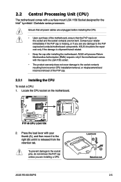
2.2 Central Processing Unit (CPU) The motherboard comes with your retailer immediately if the PnP cap is missing, or if you are not bent. ASUS shoulders the repair cost only if the damage is on the motherboard. 2. ASUS will process Return Merchandise Authorization (RMA) requests only ...a surface mount LGA 1156 Socket designed for the Intel® Lynnfield / Clarkdale series processors. Locate the CPU socket on the socket and the socket contacts are installing a CPU. ASUS RS100-E6/PI2 Load lever A B Retention tab 2-5 To prevent damage to the socket pins, do not remove the PnP...
2.2 Central Processing Unit (CPU) The motherboard comes with your retailer immediately if the PnP cap is missing, or if you are not bent. ASUS shoulders the repair cost only if the damage is on the motherboard. 2. ASUS will process Return Merchandise Authorization (RMA) requests only ...a surface mount LGA 1156 Socket designed for the Intel® Lynnfield / Clarkdale series processors. Locate the CPU socket on the socket and the socket contacts are installing a CPU. ASUS RS100-E6/PI2 Load lever A B Retention tab 2-5 To prevent damage to the socket pins, do not remove the PnP...

User Manual
Page 24
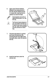
... the socket, ensuring that the gold triangle is completely lifted. DO NOT force the CPU into the CPU notches. Remove the PnP cap from the CPU socket. The CPU fits in the direction of the socket, and then fit the socket alignment keys into the socket to prevent bending the connectors on... the bottom‑left corner of the arrow until the load plate is on the socket and damaging the CPU! PnP cap 5. Load plate 4. Gold triangle mark Alignment keys CPU notches 2-6 Chapter 2: Hardware setup Lift the load lever in only one correct orientation.
... the socket, ensuring that the gold triangle is completely lifted. DO NOT force the CPU into the CPU notches. Remove the PnP cap from the CPU socket. The CPU fits in the direction of the socket, and then fit the socket alignment keys into the socket to prevent bending the connectors on... the bottom‑left corner of the arrow until the load plate is on the socket and damaging the CPU! PnP cap 5. Load plate 4. Gold triangle mark Alignment keys CPU notches 2-6 Chapter 2: Hardware setup Lift the load lever in only one correct orientation.
User Manual
Page 25
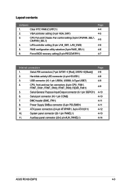
If it gets into your eyes or touches your skin, wash it . ASUS RS100-E6/PI2 2-7 Apply some Thermal Interface Material to the exposed area of the load plate slides under the retention tab. Insert the load lever under the retention ... (A), and then push down the load lever (B), ensuring that it is toxic and inedible. B A C 8. 6. Some heatsinks come with , ensuring that the front edge of the CPU that the heatsink will be in an even thin layer.
If it gets into your eyes or touches your skin, wash it . ASUS RS100-E6/PI2 2-7 Apply some Thermal Interface Material to the exposed area of the load plate slides under the retention tab. Insert the load lever under the retention ... (A), and then push down the load lever (B), ensuring that it is toxic and inedible. B A C 8. 6. Some heatsinks come with , ensuring that the front edge of the CPU that the heatsink will be in an even thin layer.

User Manual
Page 26
Protection sticker 3. Remove the protection sticker on the motherboard. 2-8 Chapter 2: Hardware setup 2.2.2 Installing the CPU heatsink and airduct To install the CPU heatsink: 1. Place the heatsink on top of the installed CPU, ensuring that the four fasteners match the holes on the back of the mylar and set it aside for installing the CPU heatsink. 2. Lift one side of the CPU heatsink.
Protection sticker 3. Remove the protection sticker on the motherboard. 2-8 Chapter 2: Hardware setup 2.2.2 Installing the CPU heatsink and airduct To install the CPU heatsink: 1. Place the heatsink on top of the installed CPU, ensuring that the four fasteners match the holes on the back of the mylar and set it aside for installing the CPU heatsink. 2. Lift one side of the CPU heatsink.
User Manual
Page 49
...[Black]) 2. Auxiliary panel connector (20-2 pin AUX_PANEL1) Page 4-8 4-8 4-9 4-9 4-10 4-10 4-11 4-11 4-12 4-13 4-14 ASUS RS100-E6/PI2 4-3 Layout contents Jumpers 1. VGA controller setting (3-pin VGA_SW1) 3. ATX power connectors (24-pin ATXPWR1, 8-pin ATX12V1) 10. Hard disk ...header (BMC_FW1) 8. Serial General Purpose Input/Output connector (6-1 pin SGPIO1) 6. CPU Fan and Chassis Fan control setting (3-pin CPUFAN_SEL1, CHAFAN_SEL1) 4. Clear RTC RAM (CLRTC1) 2. CPU, front and rear fan connectors (4-pin CPU_FAN1, FRNT_FAN1, FRNT_FAN2, FRNT_FAN3, REAR_FAN1...
...[Black]) 2. Auxiliary panel connector (20-2 pin AUX_PANEL1) Page 4-8 4-8 4-9 4-9 4-10 4-10 4-11 4-11 4-12 4-13 4-14 ASUS RS100-E6/PI2 4-3 Layout contents Jumpers 1. VGA controller setting (3-pin VGA_SW1) 3. ATX power connectors (24-pin ATXPWR1, 8-pin ATX12V1) 10. Hard disk ...header (BMC_FW1) 8. Serial General Purpose Input/Output connector (6-1 pin SGPIO1) 6. CPU Fan and Chassis Fan control setting (3-pin CPUFAN_SEL1, CHAFAN_SEL1) 4. Clear RTC RAM (CLRTC1) 2. CPU, front and rear fan connectors (4-pin CPU_FAN1, FRNT_FAN1, FRNT_FAN2, FRNT_FAN3, REAR_FAN1...
User Manual
Page 51
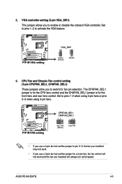
The CPUFAN_SEL1 jumper is for the CPU fans control and the CHAFAN_SEL1 jumper is for fan pin selection. 2. VGA controller setting (3-pin VGA_SW1) This jumper allows you installed will always run at ... but set the jumper for a 4-pin fan, the fan control will not work and the fan you to enable or disable the onboard VGA controller. ASUS RS100-E6/PI2 4-5 CPU Fan and Chassis Fan control setting (3-pin CPUFAN_SEL1, CHAFAN_SEL1) These jumpers allow you to activate the VGA feature. 3. Set to pins 1-2 to switch for the...
The CPUFAN_SEL1 jumper is for the CPU fans control and the CHAFAN_SEL1 jumper is for fan pin selection. 2. VGA controller setting (3-pin VGA_SW1) This jumper allows you installed will always run at ... but set the jumper for a 4-pin fan, the fan control will not work and the fan you to enable or disable the onboard VGA controller. ASUS RS100-E6/PI2 4-5 CPU Fan and Chassis Fan control setting (3-pin CPUFAN_SEL1, CHAFAN_SEL1) These jumpers allow you to activate the VGA feature. 3. Set to pins 1-2 to switch for the...
User Manual
Page 55
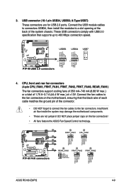
.... • These are for USB 2.0 ports. A-Type USB7) These connectors are not jumpers! USB connector (10-1 pin USB34, USB56; 3. CPU, front and rear fan connectors (4-pin CPU_FAN1, FRNT_FAN1, FRNT_FAN2, FRNT_FAN3, REAR_FAN1) The fan connectors support cooling fans of 350 mA-740 mA (8.88...NOT forget to connect the fan cables to the fan connectors on the fan connectors! • All fans feature the ASUS Fan Speed Control technology. ASUS RS100-E6/PI2 4-9 These USB connectors comply with USB 2.0 specification that the black wire of each cable matches the ground pin of ...
.... • These are for USB 2.0 ports. A-Type USB7) These connectors are not jumpers! USB connector (10-1 pin USB34, USB56; 3. CPU, front and rear fan connectors (4-pin CPU_FAN1, FRNT_FAN1, FRNT_FAN2, FRNT_FAN3, REAR_FAN1) The fan connectors support cooling fans of 350 mA-740 mA (8.88...NOT forget to connect the fan cables to the fan connectors on the fan connectors! • All fans feature the ASUS Fan Speed Control technology. ASUS RS100-E6/PI2 4-9 These USB connectors comply with USB 2.0 specification that the black wire of each cable matches the ground pin of ...

User Manual
Page 73
...Main BIOS SETUP UTILITY BIOS Information BIOS Version :0202 BIOS Build Date :09/16/09 Processor Type Speed :Intel(R) Xeon(R) CPU 2.53GHz :2533MHz X3440 @ System Memory Usable Size : 1016MB System Memory Information ←→ Select Screen ↑↓ ...BIOS SETUP UTILITY DIMM_A1 DIMM_A2 DIMM_B1 DIMM_B2 1024 MB, 1R, 1067 N/A N/A N/A ASUS RS100-E6/PI2 5-13 5.3.6 System Information This menu gives you an overview of the general system specifications. Processor Displays the auto-detected CPU specification. System Memory Displays the auto-detected system memory.
...Main BIOS SETUP UTILITY BIOS Information BIOS Version :0202 BIOS Build Date :09/16/09 Processor Type Speed :Intel(R) Xeon(R) CPU 2.53GHz :2533MHz X3440 @ System Memory Usable Size : 1016MB System Memory Information ←→ Select Screen ↑↓ ...BIOS SETUP UTILITY DIMM_A1 DIMM_A2 DIMM_B1 DIMM_B2 1024 MB, 1R, 1067 N/A N/A N/A ASUS RS100-E6/PI2 5-13 5.3.6 System Information This menu gives you an overview of the general system specifications. Processor Displays the auto-detected CPU specification. System Memory Displays the auto-detected system memory.

User Manual
Page 74
...L3 :8192 KB Ratio Status:Unlocked (Min:09, Max:19) Ratio Actual Value :19 CPUID :106E5 X3440 Sets the ratio between CPU Core Clock and the FSB Frequency. 5.4 Advanced menu The Advanced menu items allow you to Sub Screen F1 General Help F10 Save ... Megatrends, Inc. 5-14 Chapter 5: BIOS setup Main Advanced Server BIOS SETUP UTILITY Power Boot Tools CPU Configuration Chipset Onboard Device Configuration USB Configuration PCIPnP ACPI Configuration Event Log Configuration Exit Configure CPU. Some items may differ. Intel VT-d [Disabled] SR-IOV Supported [Disabled] ←→ ...
...L3 :8192 KB Ratio Status:Unlocked (Min:09, Max:19) Ratio Actual Value :19 CPUID :106E5 X3440 Sets the ratio between CPU Core Clock and the FSB Frequency. 5.4 Advanced menu The Advanced menu items allow you to Sub Screen F1 General Help F10 Save ... Megatrends, Inc. 5-14 Chapter 5: BIOS setup Main Advanced Server BIOS SETUP UTILITY Power Boot Tools CPU Configuration Chipset Onboard Device Configuration USB Configuration PCIPnP ACPI Configuration Event Log Configuration Exit Configure CPU. Some items may differ. Intel VT-d [Disabled] SR-IOV Supported [Disabled] ←→ ...

User Manual
Page 75
... [18.0] [19.0] [20.0] C1E Support [Enabled] Allows you to virtually function as several systems. Configuration options: [Disabled] [Enabled] ASUS RS100-E6/PI2 5-15 Configuration options: [Disabled] [Enabled] Intel(R) Virtualization Tech [Enabled] The Intel® Virtualization Technology allows a hardware platform to run ...] [Enabled] Hardware Prefetcher [Enabled] Allows you to boot even without support for more items. Advanced BIOS SETUP UTILITY CPU TM Function [Enabled] Execute-Disable Bit Capability [Enabled] Intel(R) HT Technology [Enabled] Active Processor Cores [All] A20M...
... [18.0] [19.0] [20.0] C1E Support [Enabled] Allows you to virtually function as several systems. Configuration options: [Disabled] [Enabled] ASUS RS100-E6/PI2 5-15 Configuration options: [Disabled] [Enabled] Intel(R) Virtualization Tech [Enabled] The Intel® Virtualization Technology allows a hardware platform to run ...] [Enabled] Hardware Prefetcher [Enabled] Allows you to boot even without support for more items. Advanced BIOS SETUP UTILITY CPU TM Function [Enabled] Execute-Disable Bit Capability [Enabled] Intel(R) HT Technology [Enabled] Active Processor Cores [All] A20M...

User Manual
Page 76
...set to zero (0). Enable this item to [Disabled] forces the XD feature flag to always return to [Disabled], the CPU runs at its default speed. Configuration options: [Disabled] [Enabled] Execute-Disable Bit Capability [Enabled] Allows you install a C-State Technology-supported... enabled. Configuratiton options: [Disabled] [ACPI C2] [ACPI C3] 5-16 Chapter 5: BIOS setup Setting this item only when you to [Enabled], the CPU speed is enabled. Configuration options: [Disabled] [Enabled] Intel(R) SpeedStep (TM) Tech [Enabled] When set to enable or disable the No-Execution Page ...
...set to zero (0). Enable this item to [Disabled] forces the XD feature flag to always return to [Disabled], the CPU runs at its default speed. Configuration options: [Disabled] [Enabled] Execute-Disable Bit Capability [Enabled] Allows you install a C-State Technology-supported... enabled. Configuratiton options: [Disabled] [ACPI C2] [ACPI C3] 5-16 Chapter 5: BIOS setup Setting this item only when you to [Enabled], the CPU speed is enabled. Configuration options: [Disabled] [Enabled] Intel(R) SpeedStep (TM) Tech [Enabled] When set to enable or disable the No-Execution Page ...

User Manual
Page 77
...to select Nehalem C state action. Configuration options: [Disabled] [Enabled] C3 Auto Demotion [Enabled] When this item is enabled, the CPU will conditionally demote C3/C6 requests to C1 based on the uncore auto-demote information. C6 State [Enabled] Allows you set this item... the C-State mode supported by your CPU. Configuration options: [Auto] [C1] [C3] [C6] C1 Auto Demotion [Enabled] When this item is enabled, the CPU will conditionally demote C6 requests to C3 based on the uncore auto-demote information. Configuration options: [Disabled] [Enabled] ASUS RS100-E6/PI2 5-17
...to select Nehalem C state action. Configuration options: [Disabled] [Enabled] C3 Auto Demotion [Enabled] When this item is enabled, the CPU will conditionally demote C3/C6 requests to C1 based on the uncore auto-demote information. C6 State [Enabled] Allows you set this item... the C-State mode supported by your CPU. Configuration options: [Auto] [C1] [C3] [C6] C1 Auto Demotion [Enabled] When this item is enabled, the CPU will conditionally demote C6 requests to C3 based on the uncore auto-demote information. Configuration options: [Disabled] [Enabled] ASUS RS100-E6/PI2 5-17

User Manual
Page 90
... [Ignored] if you to detect this item. 5-30 Chapter 5: BIOS setup 5.6.2 Hardware Monitor Hardware Monitor CPU Temperature(PECI) MB Temperature TR1 Temperature CPU Fan1 Speed FRNT FAN1 Speed FRNT FAN2 Speed FRNT FAN3 Speed REAR FAN1 Speed FAN Speed Control VCORE1 3V ...setting for more efficient system operation. Select [Ignored] if you do not want to configure the ASUS Smart Fan feature that smartly adjusts the fan speeds for the RS100-E6/PI2 server is not connected to display the detected temperatures. VCORE1, 3.3V Voltage, 5V Voltage, 12V ...
... [Ignored] if you to detect this item. 5-30 Chapter 5: BIOS setup 5.6.2 Hardware Monitor Hardware Monitor CPU Temperature(PECI) MB Temperature TR1 Temperature CPU Fan1 Speed FRNT FAN1 Speed FRNT FAN2 Speed FRNT FAN3 Speed REAR FAN1 Speed FAN Speed Control VCORE1 3V ...setting for more efficient system operation. Select [Ignored] if you do not want to configure the ASUS Smart Fan feature that smartly adjusts the fan speeds for the RS100-E6/PI2 server is not connected to display the detected temperatures. VCORE1, 3.3V Voltage, 5V Voltage, 12V ...
