PU-DLS User Manual
Page 8
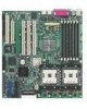
... to install SCSI, LAN, and audio drivers for various operating systems. viii It includes brief descriptions of the special attributes of the motherboard and the new technology it supports. • Chapter 2: Hardware information This chapter lists the hardware setup procedures that you need when installing the ASUS PU-DLS motherboard. How this guide This user guide...
... to install SCSI, LAN, and audio drivers for various operating systems. viii It includes brief descriptions of the special attributes of the motherboard and the new technology it supports. • Chapter 2: Hardware information This chapter lists the hardware setup procedures that you need when installing the ASUS PU-DLS motherboard. How this guide This user guide...
PU-DLS User Manual
Page 11
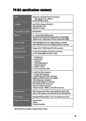
xi PU-DLS specifications summary CPU Chipsets Front Side Bus (FSB) Memory Onboard LAN Onboard SCSI Expansion slots Rear panel I/O Internal connectors BIOS features Form Factor Support CD ... panel connector Chassis intrusion, SMBus, and WOR connectors 4Mb Firmware Hub (FWH), Award BIOS with ACPI, DMI, Green, PnP features, and Enhanced Server BIOS features Extended ATX form factor: 12 in x 13 in (30.5 cm x 33 cm) Device drivers Utilities Contact information * Specifications are subject to change without notice.
xi PU-DLS specifications summary CPU Chipsets Front Side Bus (FSB) Memory Onboard LAN Onboard SCSI Expansion slots Rear panel I/O Internal connectors BIOS features Form Factor Support CD ... panel connector Chassis intrusion, SMBus, and WOR connectors 4Mb Firmware Hub (FWH), Award BIOS with ACPI, DMI, Green, PnP features, and Enhanced Server BIOS features Extended ATX form factor: 12 in x 13 in (30.5 cm x 33 cm) Device drivers Utilities Contact information * Specifications are subject to change without notice.

PU-DLS User Manual
Page 19
Compliance Both the BIOS and the hardware levels of the motherboard meet the stringent requirements for Windows NT/2000/XP. Color-coded connectors and descriptive icons make identification easy as required by the PC '99 specification. The new SDG 2.0 requirements for systems and components are based on the following high-level goals: support for Plug-and-Play compatibility and power management for configuring and managing all system components, 32-bit device drivers, and installation procedures for SDG 2.0 certification. ASUS PU-DLS motherboard user guide 1-5
Compliance Both the BIOS and the hardware levels of the motherboard meet the stringent requirements for Windows NT/2000/XP. Color-coded connectors and descriptive icons make identification easy as required by the PC '99 specification. The new SDG 2.0 requirements for systems and components are based on the following high-level goals: support for Plug-and-Play compatibility and power management for configuring and managing all system components, 32-bit device drivers, and installation procedures for SDG 2.0 certification. ASUS PU-DLS motherboard user guide 1-5
PU-DLS User Manual
Page 33
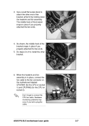
... on socket 2). Hardware monitoring problems may occur if you properly attached the two ends. 5. Do steps 2 to 4 to attach the other bracket. 6. ASUS PU-DLS motherboard user guide 2-7 3. Use a small flat screw driver to install the other end of the bracket snaps in place, connect the fan cable to connect the CPU fan cable. When...
... on socket 2). Hardware monitoring problems may occur if you properly attached the two ends. 5. Do steps 2 to 4 to attach the other bracket. 6. ASUS PU-DLS motherboard user guide 2-7 3. Use a small flat screw driver to install the other end of the bracket snaps in place, connect the fan cable to connect the CPU fan cable. When...
PU-DLS User Manual
Page 37
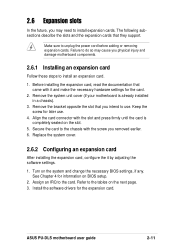
Secure the card to the card. Install the software drivers for the card. 2. The following subsections describe the slots and the expansion cards that you intend to use . 4. Before installing the expansion card, read the ... may need to the tables on the next page. 3. Remove the system unit cover (if your motherboard is completely seated on the slot. 5. Turn on the system and change the necessary BIOS settings, if any. ASUS PU-DLS motherboard user guide 2-11 Make sure to install an expansion card. 1. Remove the bracket opposite the slot...
Secure the card to the card. Install the software drivers for the card. 2. The following subsections describe the slots and the expansion cards that you intend to use . 4. Before installing the expansion card, read the ... may need to the tables on the next page. 3. Remove the system unit cover (if your motherboard is completely seated on the slot. 5. Turn on the system and change the necessary BIOS settings, if any. ASUS PU-DLS motherboard user guide 2-11 Make sure to install an expansion card. 1. Remove the bracket opposite the slot...

PU-DLS User Manual
Page 38
... Otherwise, conflicts will arise between the two PCI groups, making the system unstable and the card inoperable. PIRQA~H are usually available for this motherboard PCIX1 slot (supports ZCR) PCIX2 slot PCIX3 slot PCIX4 slot (riser slot A) PCIX4 slot (riser slot B) PCIX4 slot (riser slot ... PIRQA2 PIRQD PIRQC - - - - - PIRQAn~Bn are P64H2 PCI A/B interrupt inputs. 2-12 When using PCI cards on shared slots, ensure that the drivers support "Share IRQ" or that the cards do not need IRQ assignments. PCI INTC PIRQB9 PIRQB2 PIRQA6 PIRQA2 PIRQA1 PIRQA1 PIRQC PIRQB - - - - - ...
... Otherwise, conflicts will arise between the two PCI groups, making the system unstable and the card inoperable. PIRQA~H are usually available for this motherboard PCIX1 slot (supports ZCR) PCIX2 slot PCIX3 slot PCIX4 slot (riser slot A) PCIX4 slot (riser slot B) PCIX4 slot (riser slot ... PIRQA2 PIRQD PIRQC - - - - - PIRQAn~Bn are P64H2 PCI A/B interrupt inputs. 2-12 When using PCI cards on shared slots, ensure that the drivers support "Share IRQ" or that the cards do not need IRQ assignments. PCI INTC PIRQB9 PIRQB2 PIRQA6 PIRQA2 PIRQA1 PIRQA1 PIRQC PIRQB - - - - - ...

PU-DLS User Manual
Page 52
... (2-pin SMI) This lead connects to allow use of messages from a fax/modem. The system message LED feature requires an ACPI OS and driver support. • System Warning Speaker Lead (4-pin SPEAKER) This 4-pin connector is for the system message LED that controls the system power. ... power switch while in sleep mode. • System Message LED Lead (2-pin MLED) This 2-pin connector is for a chassis-mounted speaker. • ATX Power Switch / Soft-Off Switch Lead (2-pin PWR) This connector connects a switch that indicates receipt of the keyboard lock feature. 2-26 Chapter 2: Hardware...
... (2-pin SMI) This lead connects to allow use of messages from a fax/modem. The system message LED feature requires an ACPI OS and driver support. • System Warning Speaker Lead (4-pin SPEAKER) This 4-pin connector is for the system message LED that controls the system power. ... power switch while in sleep mode. • System Message LED Lead (2-pin MLED) This 2-pin connector is for a chassis-mounted speaker. • ATX Power Switch / Soft-Off Switch Lead (2-pin PWR) This connector connects a switch that indicates receipt of the keyboard lock feature. 2-26 Chapter 2: Hardware...
PU-DLS User Manual
Page 59
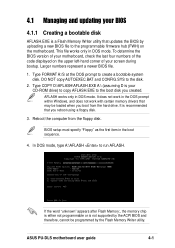
...utility that updates the BIOS by the Flash Memory Writer utility. It does not work in DOS mode. Reboot the computer from the hard drive. ASUS PU-DLS motherboard user guide 4-1 DO NOT copy AUTOEXEC.BAT and CONFIG.SYS to the programmable firmware hub (FWH) on the upper left-hand corner of your ... AFLASH.EXE to the boot disk you created. This file works only in the DOS prompt within Windows, and does not work with certain memory drivers that you boot from the floppy disk. 4.1 Managing and updating your BIOS 4.1.1 Creating a bootable disk AFLASH.EXE is not supported by the ACPI ...
...utility that updates the BIOS by the Flash Memory Writer utility. It does not work in DOS mode. Reboot the computer from the hard drive. ASUS PU-DLS motherboard user guide 4-1 DO NOT copy AUTOEXEC.BAT and CONFIG.SYS to the programmable firmware hub (FWH) on the upper left-hand corner of your ... AFLASH.EXE to the boot disk you created. This file works only in the DOS prompt within Windows, and does not work with certain memory drivers that you boot from the floppy disk. 4.1 Managing and updating your BIOS 4.1.1 Creating a bootable disk AFLASH.EXE is not supported by the ACPI ...

PU-DLS User Manual
Page 91
Chapter 5 This chapter tells how to install SCSI, LAN, and VGA drivers for various operating systems. Driver installation
Chapter 5 This chapter tells how to install SCSI, LAN, and VGA drivers for various operating systems. Driver installation
PU-DLS User Manual
Page 93
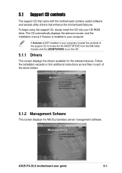
...the motherboard contains useful software and several utility drivers that enhance the motherboard features. Follow the installation wizards or find additional instructions as text files in your CD-ROM drive. To begin using the support CD, simply insert the CD into your computer. ASUS PU-DLS motherboard user... guide 5-1 If Autorun is enabled in each of the support CD to run the CD. 5.1.1 Drivers This screen displays the drivers available for the onboard devices.
...the motherboard contains useful software and several utility drivers that enhance the motherboard features. Follow the installation wizards or find additional instructions as text files in your CD-ROM drive. To begin using the support CD, simply insert the CD into your computer. ASUS PU-DLS motherboard user... guide 5-1 If Autorun is enabled in each of the support CD to run the CD. 5.1.1 Drivers This screen displays the drivers available for the onboard devices.

PU-DLS User Manual
Page 94
5.1.3 Utilities This screen displays the available system utilities that you can install. 5.1.4 Contact This screen displays the ASUS worldwide contact information. 5-2 Chapter 5: Driver installation
5.1.3 Utilities This screen displays the available system utilities that you can install. 5.1.4 Contact This screen displays the ASUS worldwide contact information. 5-2 Chapter 5: Driver installation
PU-DLS User Manual
Page 95
... display the folders and sub-folders in the support CD. 4. You must load the driver manually prior to complete the process. Using the Drivers menu in the following folder path: \drivers\adaptec\7902\ ASUS PU-DLS motherboard user guide 5-3 Click on Extract. 5. The ASUS File Image Extractor window appears. 4. A3. Insert a blank formatted high-density floppy disk into...
... display the folders and sub-folders in the support CD. 4. You must load the driver manually prior to complete the process. Using the Drivers menu in the following folder path: \drivers\adaptec\7902\ ASUS PU-DLS motherboard user guide 5-3 Click on Extract. 5. The ASUS File Image Extractor window appears. 4. A3. Insert a blank formatted high-density floppy disk into...
PU-DLS User Manual
Page 96
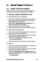
...setup. 9. Select Adaptec Ultra320 SCSI Cards (WinNT 4.0) and press Enter. 7. "Setup is DOS installed and you want to complete the installation. 5-4 Chapter 5: Driver installation For Windows NT 4.0 Boot disk installation only: When prompted, insert disk #2 in the Windows NT 4.0 documentation to add other...or the Windows NT 4.0 Boot CD-ROM in your computer system's hardware." Press S to select Other; insert the Adaptec Ultra320 FMS driver disk in the CD-ROM drive. Press Enter to Step 3. 3. Press Enter to specify an additional device. 5. The screen displays the adapter...
...setup. 9. Select Adaptec Ultra320 SCSI Cards (WinNT 4.0) and press Enter. 7. "Setup is DOS installed and you want to complete the installation. 5-4 Chapter 5: Driver installation For Windows NT 4.0 Boot disk installation only: When prompted, insert disk #2 in the Windows NT 4.0 documentation to add other...or the Windows NT 4.0 Boot CD-ROM in your computer system's hardware." Press S to select Other; insert the Adaptec Ultra320 FMS driver disk in the CD-ROM drive. Press Enter to Step 3. 3. Press Enter to specify an additional device. 5. The screen displays the adapter...

PU-DLS User Manual
Page 97
... Changing Boot Controllers in your system. 4. Click the Start button on your computer. Click the Drivers tab, then click the Add button. 6. Insert the Adaptec Ultra320 FMS driver disk in Windows NT 4.0 1. You must restart your system. Do not attach any devices to...install the Ultra320 controller into your computer for the changes to restart your system. Installing the Adaptec Ultra320 driver with existing Windows NT 4.0 1. Click Yes to take effect. ASUS PU-DLS motherboard user guide 5-5 Click OK. 9. Power on the Windows NT 4.0 task bar, then point to...
... Changing Boot Controllers in your system. 4. Click the Start button on your computer. Click the Drivers tab, then click the Add button. 6. Insert the Adaptec Ultra320 FMS driver disk in Windows NT 4.0 1. You must restart your system. Do not attach any devices to...install the Ultra320 controller into your computer for the changes to restart your system. Installing the Adaptec Ultra320 driver with existing Windows NT 4.0 1. Click Yes to take effect. ASUS PU-DLS motherboard user guide 5-5 Click OK. 9. Power on the Windows NT 4.0 task bar, then point to...
PU-DLS User Manual
Page 98
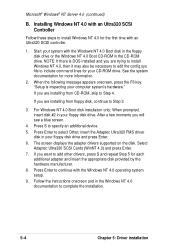
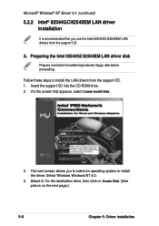
Microsoft® Windows® NT Server 4.0 (continued) 5.2.2 Intel® 82544GC/82540EM LAN driver installation It is recommended that appears, select Create Install Disk. 3. Follow these steps to install the driver. Insert the support CD into the CD-ROM drive. 2. Select A:/ for the destination drive..., then click on Create Disk. (See picture on the next page.) 5-6 Chapter 5: Driver installation Preparing the Intel 82544GC/82540EM LAN driver disk Prepare one blank formatted high density floppy disk before proceeding. The next screen allows you use the Intel ...
Microsoft® Windows® NT Server 4.0 (continued) 5.2.2 Intel® 82544GC/82540EM LAN driver installation It is recommended that appears, select Create Install Disk. 3. Follow these steps to install the driver. Insert the support CD into the CD-ROM drive. 2. Select A:/ for the destination drive..., then click on Create Disk. (See picture on the next page.) 5-6 Chapter 5: Driver installation Preparing the Intel 82544GC/82540EM LAN driver disk Prepare one blank formatted high density floppy disk before proceeding. The next screen allows you use the Intel ...
PU-DLS User Manual
Page 100
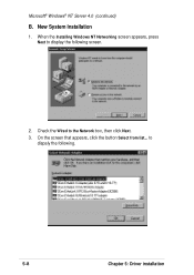
When the Installing Windows NT Networking screen appears, press Next to display the following . 5-8 Chapter 5: Driver installation Check the Wired to dispaly the following screen. 2. to the Network box, then click Next. 3. New System Installation 1. On the screen that appears, click the button Select from list... Microsoft® Windows® NT Server 4.0 (continued) B.
When the Installing Windows NT Networking screen appears, press Next to display the following . 5-8 Chapter 5: Driver installation Check the Wired to dispaly the following screen. 2. to the Network box, then click Next. 3. New System Installation 1. On the screen that appears, click the button Select from list... Microsoft® Windows® NT Server 4.0 (continued) B.

PU-DLS User Manual
Page 101
Type A:\ in the list. 8. The following screen appears showing the Intel(R) PRO/1000 Family Adapter in the dialog box that you created, then click Have Disk... 5. Follow the succeeding screen instructions. 7. When done, the following screen lists the Intel LAN adapters that appears, then click OK. Select Intel(R) PRO/1000 Family Adapter, then click OK. Click Next and follow any other screen instructions to complete the installation. Insert the LAN driver disk that you can install. 6. 4. ASUS PU-DLS motherboard user guide 5-9
Type A:\ in the list. 8. The following screen appears showing the Intel(R) PRO/1000 Family Adapter in the dialog box that you created, then click Have Disk... 5. Follow the succeeding screen instructions. 7. When done, the following screen lists the Intel LAN adapters that appears, then click OK. Select Intel(R) PRO/1000 Family Adapter, then click OK. Click Next and follow any other screen instructions to complete the installation. Insert the LAN driver disk that you can install. 6. 4. ASUS PU-DLS motherboard user guide 5-9
PU-DLS User Manual
Page 102
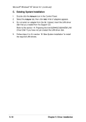
...an adapter from the Support CD. Refer to install the required LAN drivers. 5-10 Chapter 5: Driver installation Select the Adapter tab, then click Add. A list of adapters appears. 4. Preparing the Intel 82544GC/82540EM LAN Driver Disk" if you created from the list. Double-click the Network icon... in section "B. New System Installation" to the section "A. Follow steps 4 to 8 in the Control Panel. 2. Instead, insert the LAN driver disk that you have not yet ...
...an adapter from the Support CD. Refer to install the required LAN drivers. 5-10 Chapter 5: Driver installation Select the Adapter tab, then click Add. A list of adapters appears. 4. Preparing the Intel 82544GC/82540EM LAN Driver Disk" if you created from the list. Double-click the Network icon... in section "B. New System Installation" to the section "A. Follow steps 4 to 8 in the Control Panel. 2. Instead, insert the LAN driver disk that you have not yet ...
PU-DLS User Manual
Page 103
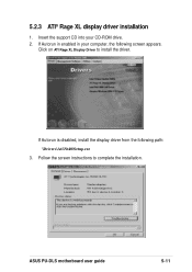
If Autorun is disabled, install the display driver from the following screen appears. If Autorun in enabled in your CD-ROM drive. 2. Click on ATI Rage XL Display Driver to complete the installation. Follow the screen instructions to install the driver. ASUS PU-DLS motherboard user guide 5-11 Insert the support CD into your computer, the following path: \Drivers\Ati\Nt40\Setup.exe 3. 5.2.3 ATI® Rage XL display driver installation 1.
If Autorun is disabled, install the display driver from the following screen appears. If Autorun in enabled in your CD-ROM drive. 2. Click on ATI Rage XL Display Driver to complete the installation. Follow the screen instructions to install the driver. ASUS PU-DLS motherboard user guide 5-11 Insert the support CD into your computer, the following path: \Drivers\Ati\Nt40\Setup.exe 3. 5.2.3 ATI® Rage XL display driver installation 1.

PU-DLS User Manual
Page 104
...\drivers\adaptec\7902\ 5-12 Chapter 5: Driver installation Click on Extract. 5. The ASUS File Image Extractor window appears. 4. Follow the succeeding screen instructions to complete the process. A3. These items are in the support CD 1. The Drivers menu appears displaying the available drivers. 3. Using the driver... the succeeding screen instructions to complete the process. You must load the driver manually prior to display the folders and sub-folders in the support CD. 4. Preparing an Adaptec Ultra320 FMS driver disk A1. Manually 1. Place the support CD into the floppy drive...
...\drivers\adaptec\7902\ 5-12 Chapter 5: Driver installation Click on Extract. 5. The ASUS File Image Extractor window appears. 4. Follow the succeeding screen instructions to complete the process. A3. These items are in the support CD 1. The Drivers menu appears displaying the available drivers. 3. Using the driver... the succeeding screen instructions to complete the process. You must load the driver manually prior to display the folders and sub-folders in the support CD. 4. Preparing an Adaptec Ultra320 FMS driver disk A1. Manually 1. Place the support CD into the floppy drive...


