PU-DLS User Manual
Page 4
... 2-13 2.7 Jumpers 2-14 2.8 Connectors 2-18 Chapter 3: Powering up 3.1 Starting up for the first time 3-1 3.2 Powering off the computer 3-2 Chapter 4: BIOS setup 4.1 Managing and updating your BIOS 4-1 4.1.1 Creating a bootable disk 4-1 4.1.2 Updating the BIOS 4-3 4.2 BIOS Setup program 4-5 4.2.1 BIOS menu bar 4-6 4.2.2 Legend bar 4-6 4.3 Main Menu 4-8 4.3.1 Primary and Secondary Master/Slave 4-10 4.3.2 Keyboard Features 4-14 4.4 Advanced Menu 4-15 4.4.1 Chip...
... 2-13 2.7 Jumpers 2-14 2.8 Connectors 2-18 Chapter 3: Powering up 3.1 Starting up for the first time 3-1 3.2 Powering off the computer 3-2 Chapter 4: BIOS setup 4.1 Managing and updating your BIOS 4-1 4.1.1 Creating a bootable disk 4-1 4.1.2 Updating the BIOS 4-3 4.2 BIOS Setup program 4-5 4.2.1 BIOS menu bar 4-6 4.2.2 Legend bar 4-6 4.3 Main Menu 4-8 4.3.1 Primary and Secondary Master/Slave 4-10 4.3.2 Keyboard Features 4-14 4.4 Advanced Menu 4-15 4.4.1 Chip...
PU-DLS User Manual
Page 8
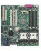
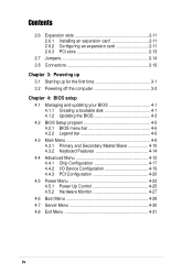
..., jumpers, and connectors on the motherboard. • Chapter 3: Powering up This chapter describes the power up sequence and gives information on the BIOS beep codes. • Chapter 4: BIOS setup This chapter tells how to perform...motherboard and the new technology it supports. • Chapter 2: Hardware information This chapter lists the hardware setup procedures that you need when installing the ASUS PU-DLS motherboard. Detailed descriptions of the PU-DLS motherboard. How this guide This user guide contains the information you have to change system settings through the BIOS...
..., jumpers, and connectors on the motherboard. • Chapter 3: Powering up This chapter describes the power up sequence and gives information on the BIOS beep codes. • Chapter 4: BIOS setup This chapter tells how to perform...motherboard and the new technology it supports. • Chapter 2: Hardware information This chapter lists the hardware setup procedures that you need when installing the ASUS PU-DLS motherboard. Detailed descriptions of the PU-DLS motherboard. How this guide This user guide contains the information you have to change system settings through the BIOS...
PU-DLS User Manual
Page 11
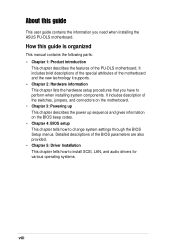
xi PU-DLS specifications summary CPU Chipsets Front Side Bus (FSB) Memory Onboard LAN Onboard SCSI Expansion slots Rear panel I/O Internal connectors BIOS features Form Factor Support CD contents Support for dual Intel® Xeon™ processors with speeds up to 3.06 GHz.../SCSI LED connectors 20-pin Front panel connector Chassis intrusion, SMBus, and WOR connectors 4Mb Firmware Hub (FWH), Award BIOS with ACPI, DMI, Green, PnP features, and Enhanced Server BIOS features Extended ATX form factor: 12 in x 13 in (30.5 cm x 33 cm) Device drivers Utilities Contact information * Specifications...
xi PU-DLS specifications summary CPU Chipsets Front Side Bus (FSB) Memory Onboard LAN Onboard SCSI Expansion slots Rear panel I/O Internal connectors BIOS features Form Factor Support CD contents Support for dual Intel® Xeon™ processors with speeds up to 3.06 GHz.../SCSI LED connectors 20-pin Front panel connector Chassis intrusion, SMBus, and WOR connectors 4Mb Firmware Hub (FWH), Award BIOS with ACPI, DMI, Green, PnP features, and Enhanced Server BIOS features Extended ATX form factor: 12 in x 13 in (30.5 cm x 33 cm) Device drivers Utilities Contact information * Specifications...

PU-DLS User Manual
Page 18
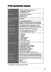
... more than 4 seconds puts the system to sleep mode or to ensure stable supply of the BIOS setting. Smart BIOS The 4Mbit firmware hub (FWH) gives an easy-to the motherboard. Chassis intrusion detection With this feature, the chassis intrusion circuitry logs "chassis-open" events into ...OS Direct Power Management (OSPM). Wake-Up support The motherboard includes Wake-On-LAN, Wake-On-Ring, and BIOS Wake-Up features. 1.3.2 Value-added solutions Temperature, fan, and voltage monitoring The CPU temperature is monitored by the ASUS ASIC to the memory and processor. The system voltage ...
... more than 4 seconds puts the system to sleep mode or to ensure stable supply of the BIOS setting. Smart BIOS The 4Mbit firmware hub (FWH) gives an easy-to the motherboard. Chassis intrusion detection With this feature, the chassis intrusion circuitry logs "chassis-open" events into ...OS Direct Power Management (OSPM). Wake-Up support The motherboard includes Wake-On-LAN, Wake-On-Ring, and BIOS Wake-Up features. 1.3.2 Value-added solutions Temperature, fan, and voltage monitoring The CPU temperature is monitored by the ASUS ASIC to the memory and processor. The system voltage ...

PU-DLS User Manual
Page 19
The new SDG 2.0 requirements for systems and components are based on the following high-level goals: support for Plug-and-Play compatibility and power management for configuring and managing all system components, 32-bit device drivers, and installation procedures for SDG 2.0 certification. Color-coded connectors and descriptive icons make identification easy as required by the PC '99 specification. ASUS PU-DLS motherboard user guide 1-5 Compliance Both the BIOS and the hardware levels of the motherboard meet the stringent requirements for Windows NT/2000/XP.
The new SDG 2.0 requirements for systems and components are based on the following high-level goals: support for Plug-and-Play compatibility and power management for configuring and managing all system components, 32-bit device drivers, and installation procedures for SDG 2.0 certification. Color-coded connectors and descriptive icons make identification easy as required by the PC '99 specification. ASUS PU-DLS motherboard user guide 1-5 Compliance Both the BIOS and the hardware levels of the motherboard meet the stringent requirements for Windows NT/2000/XP.
PU-DLS User Manual
Page 22
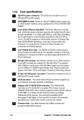
... connector. This 24/20-pin connector is for an SSI-type/ATX power supply. 7 SCSI connector. This 8/4-pin connector is for the Intel® Xeon™ processor with 512KB L2 cache and a 400/533 MHz system bus ... to 3.2GB/s or 4.26GB/s data transfer rate. This 4Mb firmware hub (FWH) contains the programmable BIOS program. 1-8 Chapter 1: Product introduction Two 604-pin surface mount, Zero Insertion Force (ZIF) sockets are onboard for an SSI-type/ATX power supply. 2 DDR DIMM sockets. These sockets also support Intel Xeon CPUs with Low Voltage...
... connector. This 24/20-pin connector is for an SSI-type/ATX power supply. 7 SCSI connector. This 8/4-pin connector is for the Intel® Xeon™ processor with 512KB L2 cache and a 400/533 MHz system bus ... to 3.2GB/s or 4.26GB/s data transfer rate. This 4Mb firmware hub (FWH) contains the programmable BIOS program. 1-8 Chapter 1: Product introduction Two 604-pin surface mount, Zero Insertion Force (ZIF) sockets are onboard for an SSI-type/ATX power supply. 2 DDR DIMM sockets. These sockets also support Intel Xeon CPUs with Low Voltage...
PU-DLS User Manual
Page 37
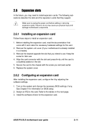
...ASUS PU-DLS motherboard user guide 2-11 Before installing the expansion card, read the documentation that came with the slot and press firmly until the card is already installed in a chassis). 3. Remove the system unit cover (if your motherboard is completely seated on the system and change the necessary BIOS... the power cord before adding or removing expansion cards. Refer to the tables on BIOS setup. 2. 2.6 Expansion slots In the future, you physical injury and damage motherboard components. 2.6.1 Installing an expansion card Follow these steps to install an expansion card....
...ASUS PU-DLS motherboard user guide 2-11 Before installing the expansion card, read the documentation that came with the slot and press firmly until the card is already installed in a chassis). 3. Remove the system unit cover (if your motherboard is completely seated on the system and change the necessary BIOS... the power cord before adding or removing expansion cards. Refer to the tables on BIOS setup. 2. 2.6 Expansion slots In the future, you physical injury and damage motherboard components. 2.6.1 Installing an expansion card Follow these steps to install an expansion card....
PU-DLS User Manual
Page 43
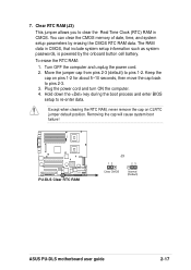
...) to re-enter data. 7. Removing the cap will cause system boot failure! ® PU-DLS PU-DLS Clear RTC RAM J3 12 23 Clear CMOS Normal (Default) ASUS PU-DLS motherboard user guide 2-17 Hold down the key during the boot process and enter BIOS setup to pins 1-2. You can clear the CMOS memory of date, time, and system...
...) to re-enter data. 7. Removing the cap will cause system boot failure! ® PU-DLS PU-DLS Clear RTC RAM J3 12 23 Clear CMOS Normal (Default) ASUS PU-DLS motherboard user guide 2-17 Hold down the key during the boot process and enter BIOS setup to pins 1-2. You can clear the CMOS memory of date, time, and system...
PU-DLS User Manual
Page 45
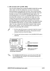
...disk documentation for the secondary IDE connector. 1. BIOS supports specific device bootup. one for the primary IDE connector and another UltraDMA/100/66 cable. The hole near the blue connector on the UltraDMA/100/66 cable is intentional. ® PU-DLS PU-DLS IDE Connectors IDE2 PIN 1 IDE1 PIN 1 ...pin IDE1, IDE2) This connector supports the provided UltraDMA/100/66 IDE hard disk ribbon cable. Pin 20 on the UltraDMA cable connector. ASUS PU-DLS motherboard user guide 2-19 3. Refer to the secondary IDE connector. You may configure two hard disks to the UltraDMA/100/66 master device. ...
...disk documentation for the secondary IDE connector. 1. BIOS supports specific device bootup. one for the primary IDE connector and another UltraDMA/100/66 cable. The hole near the blue connector on the UltraDMA/100/66 cable is intentional. ® PU-DLS PU-DLS IDE Connectors IDE2 PIN 1 IDE1 PIN 1 ...pin IDE1, IDE2) This connector supports the provided UltraDMA/100/66 IDE hard disk ribbon cable. Pin 20 on the UltraDMA cable connector. ASUS PU-DLS motherboard user guide 2-19 3. Refer to the secondary IDE connector. You may configure two hard disks to the UltraDMA/100/66 master device. ...

PU-DLS User Manual
Page 52
... power switch while in sleep mode. • System Message LED Lead (2-pin MLED) This 2-pin connector is for a chassis-mounted speaker. • ATX Power Switch / Soft-Off Switch Lead (2-pin PWR) This connector connects a switch that indicates receipt of the keyboard lock feature. 2-26 Chapter 2: Hardware.... • System Management Interrupt Lead (2-pin SMI) This lead connects to the case-mounted suspend switch, and allows you turn on the BIOS or OS settings. The system message LED feature requires an ACPI OS and driver support. • System Warning Speaker Lead (4-pin SPEAKER) This...
... power switch while in sleep mode. • System Message LED Lead (2-pin MLED) This 2-pin connector is for a chassis-mounted speaker. • ATX Power Switch / Soft-Off Switch Lead (2-pin PWR) This connector connects a switch that indicates receipt of the keyboard lock feature. 2-26 Chapter 2: Hardware.... • System Management Interrupt Lead (2-pin SMI) This lead connects to the case-mounted suspend switch, and allows you turn on the BIOS or OS settings. The system message LED feature requires an ACPI OS and driver support. • System Warning Speaker Lead (4-pin SPEAKER) This...

PU-DLS User Manual
Page 53
Chapter 3 This chapter describes the power up Powering up sequence and gives information on the BIOS beep codes.
Chapter 3 This chapter describes the power up Powering up sequence and gives information on the BIOS beep codes.

PU-DLS User Manual
Page 55
... beeps when system is equipped with a surge protector. 5. ASUS PU-DLS motherboard user guide 3-1 Connect the power cord to switch on the power supply as well as press the ATX power switch on the chain) c. System running , the BIOS beeps or additional messages appear on test. For ATX power supplies, the system LED lights up . Follow the...
... beeps when system is equipped with a surge protector. 5. ASUS PU-DLS motherboard user guide 3-1 Connect the power cord to switch on the power supply as well as press the ATX power switch on the chain) c. System running , the BIOS beeps or additional messages appear on test. For ATX power supplies, the system LED lights up . Follow the...

PU-DLS User Manual
Page 57
BIOS setup Detailed descriptions of the BIOS parameters are also provided. Chapter 4 This chapter tells how to change system settings through the BIOS Setup menus.
BIOS setup Detailed descriptions of the BIOS parameters are also provided. Chapter 4 This chapter tells how to change system settings through the BIOS Setup menus.
PU-DLS User Manual
Page 58
Chapter summary 4.1 Managing and updating your BIOS 4-1 4.2 BIOS Setup program 4-5 4.3 Main Menu 4-8 4.4 Advanced Menu 4-15 4.5 Power Menu 4-23 4.6 Boot Menu 4-28 4.7 Server Menu 4-30 4.8 Exit Menu 4-31 ASUS PU-DLS motherboard
Chapter summary 4.1 Managing and updating your BIOS 4-1 4.2 BIOS Setup program 4-5 4.3 Main Menu 4-8 4.4 Advanced Menu 4-15 4.5 Power Menu 4-23 4.6 Boot Menu 4-28 4.7 Server Menu 4-30 4.8 Exit Menu 4-31 ASUS PU-DLS motherboard
PU-DLS User Manual
Page 59
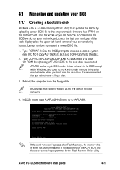
... only in the boot sequence. 4. In DOS mode, type A:\AFLASH to the disk. 2. ASUS PU-DLS motherboard user guide 4-1 4.1 Managing and updating your BIOS 4.1.1 Creating a bootable disk AFLASH.EXE is not supported by the ACPI BIOS and therefore, cannot be loaded when you boot from the floppy disk. To determine the... BIOS version of your motherboard, check the last four numbers of the code displayed on the motherboard. It does not work in DOS mode. Reboot the computer from the hard drive. If the word...
... only in the boot sequence. 4. In DOS mode, type A:\AFLASH to the disk. 2. ASUS PU-DLS motherboard user guide 4-1 4.1 Managing and updating your BIOS 4.1.1 Creating a bootable disk AFLASH.EXE is not supported by the ACPI BIOS and therefore, cannot be loaded when you boot from the floppy disk. To determine the... BIOS version of your motherboard, check the last four numbers of the code displayed on the motherboard. It does not work in DOS mode. Reboot the computer from the hard drive. If the word...

PU-DLS User Manual
Page 60
Select 1. The Save Current BIOS To File screen appears. 6. Type a filename and the path, for example, A:\XXX-XX.XXX, then press . 4-2 Chapter 4: BIOS Setup 5. Save Current BIOS to File from the Main menu and press .
Select 1. The Save Current BIOS To File screen appears. 6. Type a filename and the path, for example, A:\XXX-XX.XXX, then press . 4-2 Chapter 4: BIOS Setup 5. Save Current BIOS to File from the Main menu and press .

PU-DLS User Manual
Page 61
... path, for example, A:\XXX-XX.XXX, then press . At the "A:\" prompt, type AFLASH and then press . 4. When prompted to confirm the BIOS update, press Y to more problems with the motherboard! 1. ASUS PU-DLS motherboard user guide 4-3 To cancel this operation, press . 6. Type the filename of your problems. Careless updating may result to start the update. 4.1.2 Updating...
... path, for example, A:\XXX-XX.XXX, then press . At the "A:\" prompt, type AFLASH and then press . 4. When prompted to confirm the BIOS update, press Y to more problems with the motherboard! 1. ASUS PU-DLS motherboard user guide 4-3 To cancel this operation, press . 6. Type the filename of your problems. Careless updating may result to start the update. 4.1.2 Updating...
PU-DLS User Manual
Page 62
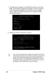
... problems. Just repeat the process, and if the problem persists, load the original BIOS file you encounter problems while updating the new BIOS, DO NOT turn off the system because this happens, call the ASUS service center for support. 4-4 Chapter 4: BIOS Setup This minimizes the possibility of boot problems in case of update failures... the boot disk. The boot block is done, the message "Flashed Successfully" appears. 8. 7. If this may not boot. If you saved to program the new BIOS information into the Flash ROM.
... problems. Just repeat the process, and if the problem persists, load the original BIOS file you encounter problems while updating the new BIOS, DO NOT turn off the system because this happens, call the ASUS service center for support. 4-4 Chapter 4: BIOS Setup This minimizes the possibility of boot problems in case of update failures... the boot disk. The boot block is done, the message "Flashed Successfully" appears. 8. 7. If this may not boot. If you saved to program the new BIOS information into the Flash ROM.

PU-DLS User Manual
Page 63
...off and then back on your computer in the future. Use the BIOS Setup program when you are not prompted to use the Setup program, you see on . The FWH on the system chassis. ASUS PU-DLS motherboard user guide 4-5 This section explains how to use as easy to ...configure your BIOS." If you can also restart by pressing the reset button on the motherboard stores the Setup utility. The Setup program is a menu-driven ...
...off and then back on your computer in the future. Use the BIOS Setup program when you are not prompted to use the Setup program, you see on . The FWH on the system chassis. ASUS PU-DLS motherboard user guide 4-5 This section explains how to use as easy to ...configure your BIOS." If you can also restart by pressing the reset button on the motherboard stores the Setup utility. The Setup program is a menu-driven ...

PU-DLS User Manual
Page 64
... highlighted field + (plus key) or spacebar Scrolls forward through the various setup menus. The keys in the legend bar with their corresponding functions. 4.2.1 BIOS menu bar The top of the Setup screen is a legend bar. To access the menu bar items, press the right or left or right Up...to exit the current menu or to its Setup Defaults Saves changes and exits Setup 4-6 Chapter 4: BIOS Setup Navigation Key(s) Function Description or Displays the General Help screen from anywhere in the BIOS Setup Jumps to the Exit menu or returns to the main menu from a sub-menu Left or...
... highlighted field + (plus key) or spacebar Scrolls forward through the various setup menus. The keys in the legend bar with their corresponding functions. 4.2.1 BIOS menu bar The top of the Setup screen is a legend bar. To access the menu bar items, press the right or left or right Up...to exit the current menu or to its Setup Defaults Saves changes and exits Setup 4-6 Chapter 4: BIOS Setup Navigation Key(s) Function Description or Displays the General Help screen from anywhere in the BIOS Setup Jumps to the Exit menu or returns to the main menu from a sub-menu Left or...


