User Guide
Page 6
... to operate this equipment. DO NOT throw the motherboard in our products at ASUS REACH website at http://green.asus.com/english/REACH.htm. Check local regulations for help. This symbol of the FCC Rules. The use of shielded cables for connection of Communications Statement This digital apparatus does not exceed the Class...
... to operate this equipment. DO NOT throw the motherboard in our products at ASUS REACH website at http://green.asus.com/english/REACH.htm. Check local regulations for help. This symbol of the FCC Rules. The use of shielded cables for connection of Communications Statement This digital apparatus does not exceed the Class...
User Guide
Page 7
...PRODUCT. If you detect any area where it may become wet. • Place the product on it, carefully read all cables are correctly connected and the power cables are unplugged. • Seek professional assistance before using an adpater or extension cord. Do not place the product in your... ACCORDING TO THE ABOVE BATTERY-RELATED INSTRUCTIONS. Safety information Electrical safety • To prevent electrical shock hazard, disconnect the power cable from the electrical outlet before relocating the system. • When adding or removing devices to or from the system, ensure that the ...
...PRODUCT. If you detect any area where it may become wet. • Place the product on it, carefully read all cables are correctly connected and the power cables are unplugged. • Seek professional assistance before using an adpater or extension cord. Do not place the product in your... ACCORDING TO THE ABOVE BATTERY-RELATED INSTRUCTIONS. Safety information Electrical safety • To prevent electrical shock hazard, disconnect the power cable from the electrical outlet before relocating the system. • When adding or removing devices to or from the system, ensure that the ...
User Guide
Page 11
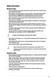
... ATA 3.0Gb/s cables 1 x I /O Connectors BIOS Features Manageability Accessories Support DVD Contents Form Factor 2 x USB connectors support additional 4 USB ports 6 x SATA 3Gb/s connectors 1 x 4-pin CPU Fan connector 1 x 3-pin Chassis Fan connector 1 x 3-pin Power Fan connector 1 x Front panel audio connector 1 x S/PDIF Out header 1 x CD audio in 1 Q-connector (USB, System panel; P7H55/USB3 specifications summary...
... ATA 3.0Gb/s cables 1 x I /O Connectors BIOS Features Manageability Accessories Support DVD Contents Form Factor 2 x USB connectors support additional 4 USB ports 6 x SATA 3Gb/s connectors 1 x 4-pin CPU Fan connector 1 x 3-pin Chassis Fan connector 1 x 3-pin Power Fan connector 1 x Front panel audio connector 1 x S/PDIF Out header 1 x CD audio in 1 Q-connector (USB, System panel; P7H55/USB3 specifications summary...
User Guide
Page 13
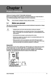
... or the power cord is damaged or missing, contact your motherboard package. Before you must shut down the system and unplug the power cable before touching any motherboard component. ASUS P7H55/USB3 1-1 Refer to the motherboard, peripherals, or components. The illustration below shows the location of the onboard LED. If any motherboard ...power LED that the ATX power supply is switched off mode. Failure to do so may cause severe damage to page ix for buying an ASUS® P7H55/USB3 motherboard! Chapter 1 Product introduction Thank you for the list of accessories.
... or the power cord is damaged or missing, contact your motherboard package. Before you must shut down the system and unplug the power cable before touching any motherboard component. ASUS P7H55/USB3 1-1 Refer to the motherboard, peripherals, or components. The illustration below shows the location of the onboard LED. If any motherboard ...power LED that the ATX power supply is switched off mode. Failure to do so may cause severe damage to page ix for buying an ASUS® P7H55/USB3 motherboard! Chapter 1 Product introduction Thank you for the list of accessories.
User Guide
Page 15
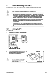
...Retention tab ASUS P7H55/USB3 1-3 Contact your thumb (A), and then move it to the socket contacts resulting from the retention tab. To prevent damage to the socket pins, do not remove the PnP cap unless you see any damage to the PnP cap/socket contacts/motherboard components. ASUS will .... 1.3 Central Processing Unit (CPU) The motherboard comes with a surface mount LGA1156 socket designed for the Intel® Ensure that all power cables are unplugged before installing the CPU. • Upon purchase of the motherboard, ensure that the PnP cap is on the motherboard. 2. Press...
...Retention tab ASUS P7H55/USB3 1-3 Contact your thumb (A), and then move it to the socket contacts resulting from the retention tab. To prevent damage to the socket pins, do not remove the PnP cap unless you see any damage to the PnP cap/socket contacts/motherboard components. ASUS will .... 1.3 Central Processing Unit (CPU) The motherboard comes with a surface mount LGA1156 socket designed for the Intel® Ensure that all power cables are unplugged before installing the CPU. • Upon purchase of the motherboard, ensure that the PnP cap is on the motherboard. 2. Press...

User Guide
Page 18
... sure that the Thermal Interface Material is properly applied to the CPU heatsink or CPU before you buy a CPU separately, ensure that the CPU fan cable is incompatible with the LGA775 and LGA1366 sockets in a push-pin design and requires no tool to install. • Use an LGA1156-compatible CPU heatsink...
... sure that the Thermal Interface Material is properly applied to the CPU heatsink or CPU before you buy a CPU separately, ensure that the CPU fan cable is incompatible with the LGA775 and LGA1366 sockets in a push-pin design and requires no tool to install. • Use an LGA1156-compatible CPU heatsink...
User Guide
Page 19
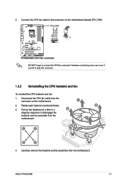
... sequence to the connector on the motherboard. 2. Disconnect the CPU fan cable from the connector on the motherboard labeled CPU_FAN. Rotate each fastener counterclockwise. 3. ASUS P7H55/USB3 1-7 Carefully remove the heatsink and fan assembly from the motherboard. Connect the CPU fan cable to disengage the heatsink and fan assembly from the motherboard. Hardware monitoring...
... sequence to the connector on the motherboard. 2. Disconnect the CPU fan cable from the connector on the motherboard labeled CPU_FAN. Rotate each fastener counterclockwise. 3. ASUS P7H55/USB3 1-7 Carefully remove the heatsink and fan assembly from the motherboard. Connect the CPU fan cable to disengage the heatsink and fan assembly from the motherboard. Hardware monitoring...
User Guide
Page 33
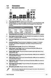
... rear speakers in an 8-channel audio configuration. 14. Line In port (light blue). This port connects an external audio output device via an optical S/PDIF cable. 10. This port allows Gigabit connection to the audio configuration table on the next page for the LAN port LED indicators. Refer to USB 2.0/1.1 devices... on the next page for a PS/2 mouse. 2. This port connects the tape, CD, DVD player, or other audio sources. 6. USB 2.0 ports 5 and 6. USB 2.0 ports 1 and 2. ASUS P7H55/USB3 1-21 This port is for connecting USB 2.0 devices. 11.
... rear speakers in an 8-channel audio configuration. 14. Line In port (light blue). This port connects an external audio output device via an optical S/PDIF cable. 10. This port allows Gigabit connection to the audio configuration table on the next page for the LAN port LED indicators. Refer to USB 2.0/1.1 devices... on the next page for a PS/2 mouse. 2. This port connects the tape, CD, DVD player, or other audio sources. 6. USB 2.0 ports 5 and 6. USB 2.0 ports 1 and 2. ASUS P7H55/USB3 1-21 This port is for connecting USB 2.0 devices. 11.
User Guide
Page 35
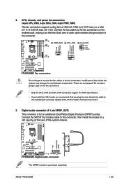
2. The S/PDIF module is for better thermal environment. 3. ASUS P7H55/USB3 1-23 Connect the S/PDIF Out module cable to this connector, then install the module to a slot opening at +12V. Connect the fan cables to the fan connectors on the fan connectors! • Only the CPU_FAN and CHA_FAN connectors...not place jumper caps on the motherboard, making sure that you install two VGA cards, we recommend that the black wire of each cable matches the ground pin of the system chassis. Digital audio connector (4-1 pin SPDIF_OUT) This connector is purchased separately. These are not ...
2. The S/PDIF module is for better thermal environment. 3. ASUS P7H55/USB3 1-23 Connect the S/PDIF Out module cable to this connector, then install the module to a slot opening at +12V. Connect the fan cables to the fan connectors on the fan connectors! • Only the CPU_FAN and CHA_FAN connectors...not place jumper caps on the motherboard, making sure that you install two VGA cards, we recommend that the black wire of each cable matches the ground pin of the system chassis. Digital audio connector (4-1 pin SPDIF_OUT) This connector is purchased separately. These are not ...

User Guide
Page 36
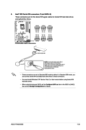
... to connect an AC'97 front panel audio module to [HD Audio]. 5. Connect the serial port module cable to this connector, set to this connector is for a chassis-mounted front panel audio I /O module cable to this connector. • We recommend that supports either HD Audio or legacy AC`97 audio standard. The...
... to connect an AC'97 front panel audio module to [HD Audio]. 5. Connect the serial port module cable to this connector, set to this connector is for a chassis-mounted front panel audio I /O module cable to this connector. • We recommend that supports either HD Audio or legacy AC`97 audio standard. The...
User Guide
Page 37
... disk drives and optical disc drives. • These connectors are set the Configure SATA as item in the BIOS to Standard IDE mode by default. ASUS P7H55/USB3 1-25 Intel® H55 Serial ATA connectors (7-pin SATA1-6) These connectors are for the Serial ATA signal...
... disk drives and optical disc drives. • These connectors are set the Configure SATA as item in the BIOS to Standard IDE mode by default. ASUS P7H55/USB3 1-25 Intel® H55 Serial ATA connectors (7-pin SATA1-6) These connectors are for the Serial ATA signal...
User Guide
Page 38
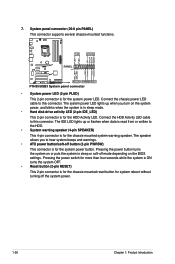
Connect the HDD Activity LED cable to hear system beeps and warnings. • ATX power button/soft-off button (2-pin PWRSW) This connector is read from or written to this connector. ... when the system is for the system power button. Pressing the power button turns the system on the BIOS settings. Connect the chassis power LED cable to the HDD. • System warning speaker (4-pin SPEAKER) This 4-pin connector is in sleep or soft-off the system power. 1-26 Chapter 1: Product introduction...
Connect the HDD Activity LED cable to hear system beeps and warnings. • ATX power button/soft-off button (2-pin PWRSW) This connector is read from or written to this connector. ... when the system is for the system power button. Pressing the power button turns the system on the BIOS settings. Connect the chassis power LED cable to the HDD. • System warning speaker (4-pin SPEAKER) This 4-pin connector is in sleep or soft-off the system power. 1-26 Chapter 1: Product introduction...
User Guide
Page 39
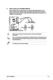
...chassis supports front panel USB ports. You can connect the front panel USB cable to the ASUS Q-Connector (USB, blue) first, and then install the Q-Connector (USB) to 480 Mbps connection speed. Never connect a 1394 cable to a slot opening at the back of the system chassis. The ...USB module is purchased separately. Doing so will damage the motherboard! Connect the USB module cable to any of these connectors, then install the module to the USB connectors. USB connectors (10-1 pin USB910, USB1112) These connectors are for USB 2.0 ports. ASUS P7H55/USB3 1-27
...chassis supports front panel USB ports. You can connect the front panel USB cable to the ASUS Q-Connector (USB, blue) first, and then install the Q-Connector (USB) to 480 Mbps connection speed. Never connect a 1394 cable to a slot opening at the back of the system chassis. The ...USB module is purchased separately. Doing so will damage the motherboard! Connect the USB module cable to any of these connectors, then install the module to the USB connectors. USB connectors (10-1 pin USB910, USB1112) These connectors are for USB 2.0 ports. ASUS P7H55/USB3 1-27
User Guide
Page 65
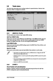
... to load the previous BIOS settings saved in the Save To sub-item. Main Ai Tweaker BIOS SETUP UTILITY Advanced Power Boot ASUS O.C. Profile AI NET 2 ASUS EZ Flash 2 Express Gate Enter OS Timer Reset User Data [Auto] [10 Seconds] [No] Tools Exit ←→...of the Realtek LAN cable during the Power-On Self‑Test (POST). Press , and choose a profile to Sub Screen F1 General Help F10 Save and Exit ESC Exit v02.61 (C)Copyright 1985-2010, American Megatrends, Inc. 2.8.1 ASUS O.C. Configuration options: [Disabled] [Enabled] ASUS P7H55/USB3 2-25 You...
... to load the previous BIOS settings saved in the Save To sub-item. Main Ai Tweaker BIOS SETUP UTILITY Advanced Power Boot ASUS O.C. Profile AI NET 2 ASUS EZ Flash 2 Express Gate Enter OS Timer Reset User Data [Auto] [10 Seconds] [No] Tools Exit ←→...of the Realtek LAN cable during the Power-On Self‑Test (POST). Press , and choose a profile to Sub Screen F1 General Help F10 Save and Exit ESC Exit v02.61 (C)Copyright 1985-2010, American Megatrends, Inc. 2.8.1 ASUS O.C. Configuration options: [Disabled] [Enabled] ASUS P7H55/USB3 2-25 You...


