
Motherboard Installation Guide
Page 17
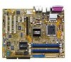
... features and latest technologies, making it , check the items in your package with the list below. 1.2 Package contents Check your retailer. ASUS P5RD1-V Deluxe 1-1 1.1 Welcome! Before you for the following items. Motherboard ASUS P5RD1-V Deluxe motherboard I/O modules 1 x TV-out/capture-in module 1 x Serial port module 1 x IEEE 1394a (1 port) module 1 x USB 2.0 (2 ports) and Game (1 port) module Cables...
... features and latest technologies, making it , check the items in your package with the list below. 1.2 Package contents Check your retailer. ASUS P5RD1-V Deluxe 1-1 1.1 Welcome! Before you for the following items. Motherboard ASUS P5RD1-V Deluxe motherboard I/O modules 1 x TV-out/capture-in module 1 x Serial port module 1 x IEEE 1394a (1 port) module 1 x USB 2.0 (2 ports) and Game (1 port) module Cables...
Motherboard Installation Guide
Page 19
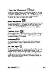
...) data interfacing between computers, peripherals, and consumer electronic devices such as camcorders, VCRs, printers,TVs, and digital cameras. See pages 2-24 and 2-33 for details. ASUS P5RD1-V Deluxe 1-3 The SATA specification allows for details. See page 5-35 for details. The IEEE 1394a interface allows up to meet your computer to home theater decoders...
...) data interfacing between computers, peripherals, and consumer electronic devices such as camcorders, VCRs, printers,TVs, and digital cameras. See pages 2-24 and 2-33 for details. ASUS P5RD1-V Deluxe 1-3 The SATA specification allows for details. See page 5-35 for details. The IEEE 1394a interface allows up to meet your computer to home theater decoders...
Motherboard Installation Guide
Page 21
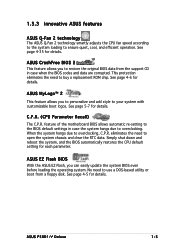
... to the system loading to overclocking, C.P.R. ASUS CrashFree BIOS 2 This feature allows you to use a DOS-based utility or boot from the support CD in case the system hangs due to your system with customizable boot logos. ASUS P5RD1-V Deluxe 1-5 No need to restore the original BIOS... data from a floppy disk. See page 4-35 for each parameter. ASUS MyLogo™ 2 This feature allows you can easily update the system BIOS ...
... to the system loading to overclocking, C.P.R. ASUS CrashFree BIOS 2 This feature allows you to use a DOS-based utility or boot from the support CD in case the system hangs due to your system with customizable boot logos. ASUS P5RD1-V Deluxe 1-5 No need to restore the original BIOS... data from a floppy disk. See page 4-35 for each parameter. ASUS MyLogo™ 2 This feature allows you can easily update the system BIOS ...

Motherboard Installation Guide
Page 24
Chapter summary 2 2.1 Before you proceed 2-1 2.2 Motherboard overview 2-2 2.3 Central Processing Unit (CPU 2-6 2.4 System memory 2-13 2.5 Expansion slots 2-18 2.6 Jumpers 2-21 2.7 Connectors 2-24 ASUS P5RD1-V Deluxe
Chapter summary 2 2.1 Before you proceed 2-1 2.2 Motherboard overview 2-2 2.3 Central Processing Unit (CPU 2-6 2.4 System memory 2-13 2.5 Expansion slots 2-18 2.6 Jumpers 2-21 2.7 Connectors 2-24 ASUS P5RD1-V Deluxe
Motherboard Installation Guide
Page 25
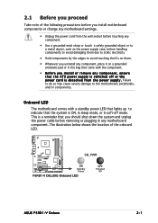
... or in the bag that came with a standby power LED that lights up to the motherboard, peripherals, and/or components. P5RD1-V ® SB_PWR ON Standby Power P5RD1-V DELUXE Onboard LED OFF Powered Off ASUS P5RD1-V Deluxe 2-1 The illustration below shows the location of the following precautions before you install motherboard components or change any motherboard settings...
... or in the bag that came with a standby power LED that lights up to the motherboard, peripherals, and/or components. P5RD1-V ® SB_PWR ON Standby Power P5RD1-V DELUXE Onboard LED OFF Powered Off ASUS P5RD1-V Deluxe 2-1 The illustration below shows the location of the following precautions before you install motherboard components or change any motherboard settings...

Motherboard Installation Guide
Page 29
...) - Reset switch (Blue 2-pin RESET) Page 2-26 2-27 2-28 2-29 2-29 2-29 2-30 2-30 2-31 2-31 2-32 2-32 2-33 2-33 2-34 2-34 2-35 2-35 2-36 ASUS P5RD1-V Deluxe 2-5 IDE connectors (40-1 pin PRI_IDE, 40-1 pin SEC IDE) 3. Serial port connector (10-1 pin COM1) 8. Optical drive audio connector (4-pin CD) 12. Chassis intrusion connector...
...) - Reset switch (Blue 2-pin RESET) Page 2-26 2-27 2-28 2-29 2-29 2-29 2-30 2-30 2-31 2-31 2-32 2-32 2-33 2-33 2-34 2-34 2-35 2-35 2-36 ASUS P5RD1-V Deluxe 2-5 IDE connectors (40-1 pin PRI_IDE, 40-1 pin SEC IDE) 3. Serial port connector (10-1 pin COM1) 8. Optical drive audio connector (4-pin CD) 12. Chassis intrusion connector...

Motherboard Installation Guide
Page 31
... is on the bottom-left corner of the arrow to a B 100º angle (A), then push the PnP cap from the retention tab. 2. Gold triangle mark ASUS P5RD1-V Deluxe A 2-7
... is on the bottom-left corner of the arrow to a B 100º angle (A), then push the PnP cap from the retention tab. 2. Gold triangle mark ASUS P5RD1-V Deluxe A 2-7
Motherboard Installation Guide
Page 33
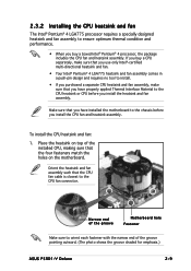
... CPU before you install the CPU fan and heatsink assembly. Narrow end of the groove pointing outward. (The photo shows the groove shaded for emphasis.) ASUS P5RD1-V Deluxe 2-9 If you buy a CPU separately, make sure that you use only Intel®-certified multi-directional heatsink and fan. • Your Intel® Pentium®...
... CPU before you install the CPU fan and heatsink assembly. Narrow end of the groove pointing outward. (The photo shows the groove shaded for emphasis.) ASUS P5RD1-V Deluxe 2-9 If you buy a CPU separately, make sure that you use only Intel®-certified multi-directional heatsink and fan. • Your Intel® Pentium®...

Motherboard Installation Guide
Page 35
Rotate each fastener counterclockwise. 3. Pull up two fasteners at a time in a diagonal sequence to disengage the heatsink B and fan assembly from the connector on the motherboard. 2. Disconnect the CPU fan cable from the A motherboard. A B A B B A ASUS P5RD1-V Deluxe 2-11 2.3.3 Uninstalling the CPU heatsink and fan To uninstall the CPU heatsink and fan: 1.
Rotate each fastener counterclockwise. 3. Pull up two fasteners at a time in a diagonal sequence to disengage the heatsink B and fan assembly from the connector on the motherboard. 2. Disconnect the CPU fan cable from the A motherboard. A B A B B A ASUS P5RD1-V Deluxe 2-11 2.3.3 Uninstalling the CPU heatsink and fan To uninstall the CPU heatsink and fan: 1.
Motherboard Installation Guide
Page 37
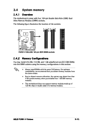
...memory when you installed four 1 GB DDR memory modules. • This motherboard does not support memory modules made up of the sockets: P5RD1-V ® P5RD1-V DELUXE 184-pin DDR DIMM sockets 2.4.2 Memory Configurations You may install 256 MB, 512 MB, and 1 GB unbuffered non-ECC DDR DIMMs ... in this section. • Always install DIMMs with four 184-pin Double Data Rate (DDR) Dual Inline Memory Modules (DIMM) sockets. ASUS P5RD1-V Deluxe 2-13 The following figure illustrates the location of 128 Mb chips or double sided x16 memory modules. DIMM_A1 DIMM_A2 DIMM_B1 DIMM_B2 2.4 System memory...
...memory when you installed four 1 GB DDR memory modules. • This motherboard does not support memory modules made up of the sockets: P5RD1-V ® P5RD1-V DELUXE 184-pin DDR DIMM sockets 2.4.2 Memory Configurations You may install 256 MB, 512 MB, and 1 GB unbuffered non-ECC DDR DIMMs ... in this section. • Always install DIMMs with four 184-pin Double Data Rate (DDR) Dual Inline Memory Modules (DIMM) sockets. ASUS P5RD1-V Deluxe 2-13 The following figure illustrates the location of 128 Mb chips or double sided x16 memory modules. DIMM_A1 DIMM_A2 DIMM_B1 DIMM_B2 2.4 System memory...
Motherboard Installation Guide
Page 41
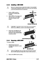
... when it fits in place and the DIMM is keyed with a notch so that it flips out with your fingers when pressing the retaining clips. ASUS P5RD1-V Deluxe 2-17 Failure to do so may cause severe damage to unplug the power supply before adding or removing DIMMs or other system components. Firmly insert...
... when it fits in place and the DIMM is keyed with a notch so that it flips out with your fingers when pressing the retaining clips. ASUS P5RD1-V Deluxe 2-17 Failure to do so may cause severe damage to unplug the power supply before adding or removing DIMMs or other system components. Firmly insert...
Motherboard Installation Guide
Page 43
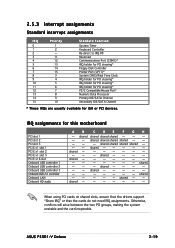
... slot 3 PCI E x16 slot Onboard USB controller 1 Onboard USB controller 2 Onboard USB controller 3 Onboard USB 2.0 controller Onboard LAN Onboard HD audio A B C D E F G H - shared shared shared shared - ASUS P5RD1-V Deluxe 2-19
... slot 3 PCI E x16 slot Onboard USB controller 1 Onboard USB controller 2 Onboard USB controller 3 Onboard USB 2.0 controller Onboard LAN Onboard HD audio A B C D E F G H - shared shared shared shared - ASUS P5RD1-V Deluxe 2-19

Motherboard Installation Guide
Page 45
... CMOS RTC RAM data. Keep the cap on CLRTC jumper default position. For system failure due to pins 1-2. 4. P5RD1-V ® CLRTC 2 1 Normal (Default) 3 2 Clear CMOS P5RD1-V DELUXE Clear RTC RAM You do not need to clear the RTC when the system hangs due to default values. You can...remove the cap on pins 2-3 for about 5~10 seconds, then move the cap back to overclocking, use the C.P.R. (CPU Parameter Recall) feature. ASUS P5RD1-V Deluxe 2-21 Clear RTC RAM (CLRTC) This jumper allows you to clear the Real Time Clock (RTC) RAM in CMOS, which include system setup information...
... CMOS RTC RAM data. Keep the cap on CLRTC jumper default position. For system failure due to pins 1-2. 4. P5RD1-V ® CLRTC 2 1 Normal (Default) 3 2 Clear CMOS P5RD1-V DELUXE Clear RTC RAM You do not need to clear the RTC when the system hangs due to default values. You can...remove the cap on pins 2-3 for about 5~10 seconds, then move the cap back to overclocking, use the C.P.R. (CPU Parameter Recall) feature. ASUS P5RD1-V Deluxe 2-21 Clear RTC RAM (CLRTC) This jumper allows you to clear the Real Time Clock (RTC) RAM in CMOS, which include system setup information...
Motherboard Installation Guide
Page 47
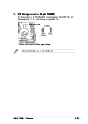
ASUS P5RD1-V Deluxe 2-23 3 . CPU Fan type selector (3-pin FANSEL) Set this jumper to 1-2 (Default) if you are using a 3-pin CPU fan. FANSEL P5RD1-V ® 2 1 4-pin CPU fan (Default) 3 2 3-pin CPU fan P5RD1-V DELUXE CPU Fan type setting We recommend the use of a 4-pin CPU fan. Set this jumper to 2-3 if you are using a 4-pin CPU fan.
ASUS P5RD1-V Deluxe 2-23 3 . CPU Fan type selector (3-pin FANSEL) Set this jumper to 1-2 (Default) if you are using a 3-pin CPU fan. FANSEL P5RD1-V ® 2 1 4-pin CPU fan (Default) 3 2 3-pin CPU fan P5RD1-V DELUXE CPU Fan type setting We recommend the use of a 4-pin CPU fan. Set this jumper to 2-3 if you are using a 4-pin CPU fan.
Motherboard Installation Guide
Page 49
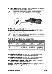
... Center/Subwoofer 8-channel Line In Front Speaker Out Mic In Rear Speaker Out Side Speaker Out Center/Subwoofer 1 1 . This port is for connecting USB 2.0 devices. 1 2 . ASUS P5RD1-V Deluxe 2-25 T V I n p o r t . P S / 2 k e y b o a r d p o r t ( p u r p l e ) . C e n t e r / S u b w o o f e r p o r t ( y e l l o w o r a n g e ) . Refer to watch and record live TV on your desktop computer. U S B 2 . 0 p o r t s 1 a n d 2 . V i d e o G r a p h i c s A d a p t e r ( V G A ) p o r t . This port is for the function of the audio ports in your motherboard...
... Center/Subwoofer 8-channel Line In Front Speaker Out Mic In Rear Speaker Out Side Speaker Out Center/Subwoofer 1 1 . This port is for connecting USB 2.0 devices. 1 2 . ASUS P5RD1-V Deluxe 2-25 T V I n p o r t . P S / 2 k e y b o a r d p o r t ( p u r p l e ) . C e n t e r / S u b w o o f e r p o r t ( y e l l o w o r a n g e ) . Refer to watch and record live TV on your desktop computer. U S B 2 . 0 p o r t s 1 a n d 2 . V i d e o G r a p h i c s A d a p t e r ( V G A ) p o r t . This port is for the function of the audio ports in your motherboard...
Motherboard Installation Guide
Page 51
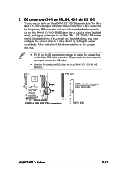
...hard disk drives, you connect the IDE cable. • Use the 80-conductor IDE cable for Ultra DMA 133/100/66 IDE devices. SEC_IDE ASUS P5RD1-V Deluxe 2-27 This prevents incorrect insertion when you must configure the second drive as a slave device by setting its jumper accordingly. IDE connectors (40-1... • Pin 20 on the IDE connector is for an Ultra DMA 133/100/66 IDE master device (hard disk drive). PRI_IDE P5RD1-V ® PIN 1 P5RD1-V DELUXE IDE connectors NOTE: Orient the red markings (usually zigzag) on the Ultra DMA cable connector. The Ultra DMA 133/100/66 signal ...
...hard disk drives, you connect the IDE cable. • Use the 80-conductor IDE cable for Ultra DMA 133/100/66 IDE devices. SEC_IDE ASUS P5RD1-V Deluxe 2-27 This prevents incorrect insertion when you must configure the second drive as a slave device by setting its jumper accordingly. IDE connectors (40-1... • Pin 20 on the IDE connector is for an Ultra DMA 133/100/66 IDE master device (hard disk drive). PRI_IDE P5RD1-V ® PIN 1 P5RD1-V DELUXE IDE connectors NOTE: Orient the red markings (usually zigzag) on the Ultra DMA cable connector. The Ultra DMA 133/100/66 signal ...
Motherboard Installation Guide
Page 53
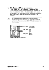
... forget to connect the fan cables to the fan connectors on the fan connectors. P5RD1-V ® CPU_FAN CHA_FAN1 PWR_FAN CPU_FAN CPU FAN PWM CPU FAN IN CPU FAN PWR CHA_FAN1 Rotation +12V GND PWR_FAN GND +12V Rotation P5RD1-V DELUXE Fan connectors ASUS P5RD1-V Deluxe 2-29 4 . Insufficient air flow inside the system may damage the motherboard components...
... forget to connect the fan cables to the fan connectors on the fan connectors. P5RD1-V ® CPU_FAN CHA_FAN1 PWR_FAN CPU_FAN CPU FAN PWM CPU FAN IN CPU FAN PWR CHA_FAN1 Rotation +12V GND PWR_FAN GND +12V Rotation P5RD1-V DELUXE Fan connectors ASUS P5RD1-V Deluxe 2-29 4 . Insufficient air flow inside the system may damage the motherboard components...
Motherboard Installation Guide
Page 55
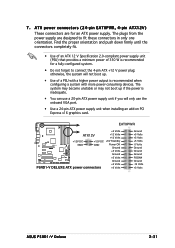
... ATX12V +12 Volts +12 Volts +12V DC +12V DC +5V Standby P5RD1-V ® GND GND Power OK Ground +5 Volts Ground +5 Volts Ground P5RD1-V DELUXE ATX power connectors +3 Volts +3 Volts Ground +5 Volts +5 Volts +5 Volts -5 Volts Ground Ground Ground PSON# Ground -12 Volts +3 Volts ASUS P5RD1-V Deluxe 2-31 ATX power connectors (24-pin EATXPWR, 4-pin ATX12V) These connectors...
... ATX12V +12 Volts +12 Volts +12V DC +12V DC +5V Standby P5RD1-V ® GND GND Power OK Ground +5 Volts Ground +5 Volts Ground P5RD1-V DELUXE ATX power connectors +3 Volts +3 Volts Ground +5 Volts +5 Volts +5 Volts -5 Volts Ground Ground Ground PSON# Ground -12 Volts +3 Volts ASUS P5RD1-V Deluxe 2-31 ATX power connectors (24-pin EATXPWR, 4-pin ATX12V) These connectors...

Motherboard Installation Guide
Page 57
... or switch. IEEE 1394a connector (10-1 pin IE1394_1) This connector is removed or replaced. Remove the jumper caps only when you intend to this connector. ASUS P5RD1-V Deluxe 2-33 By default, the pins labeled "Chassis Signal" and "Ground" are shorted with a jumper cap. The chassis intrusion sensor or switch sends a high-level signal...
... or switch. IEEE 1394a connector (10-1 pin IE1394_1) This connector is removed or replaced. Remove the jumper caps only when you intend to this connector. ASUS P5RD1-V Deluxe 2-33 By default, the pins labeled "Chassis Signal" and "Ground" are shorted with a jumper cap. The chassis intrusion sensor or switch sends a high-level signal...
Motherboard Installation Guide
Page 59
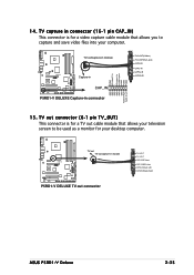
... capture cable module that allows your television screen to capture and save video files into your desktop computer. TV-out/capture-in module P5RD1-V ® Capture-in CAP_IN P5RD1-V DELUXE Capture-in connector GND S-video C-in S-video Y-in CVBS inputs GND GND GND TV S-OUT(S-Video) TV C-OUT(RCA Jack) ...IN GND GND GND GND GND GND Audio in Right Audio in module P5RD1-V DELUXE TV-out connector TV S-OUT TV C-OUT CAP S-IN(S Video) CAP C-IN(RCA Jack) CAP AL-IN(Audio Left) CAP AR-IN(Audio Right) ASUS P5RD1-V Deluxe 2-35 TV out connector (6-1 pin TV_OUT) This connector is for your ...
... capture cable module that allows your television screen to capture and save video files into your desktop computer. TV-out/capture-in module P5RD1-V ® Capture-in CAP_IN P5RD1-V DELUXE Capture-in connector GND S-video C-in S-video Y-in CVBS inputs GND GND GND TV S-OUT(S-Video) TV C-OUT(RCA Jack) ...IN GND GND GND GND GND GND Audio in Right Audio in module P5RD1-V DELUXE TV-out connector TV S-OUT TV C-OUT CAP S-IN(S Video) CAP C-IN(RCA Jack) CAP AL-IN(Audio Left) CAP AR-IN(Audio Right) ASUS P5RD1-V Deluxe 2-35 TV out connector (6-1 pin TV_OUT) This connector is for your ...


