
User Manual
Page 1
P5QPL-AM Motherboard
P5QPL-AM Motherboard

User Manual
Page 3
Contents Notices...vi Safety information vii About this guide vii P5QPL-AM specifications summary ix Chapter 1: Product introduction 1.1 Welcome 1-1 1.2 Package contents 1-1 1.3 Special features 1-1 1.3.1 Product highlights 1-1 1.3.2 Innovative ASUS features 1-2 1.4 Before you proceed 1-4 1.5 Motherboard overview 1-5 1.5.1 Placement direction 1-5 1.5.2 Screw holes 1-5 1.5.3 Motherboard layout 1-6 1.5.4 Layout contents 1-6 1.6 Central Processing Unit (CPU 1-7 1.6.1 Installing the CPU 1-7 1.6.2 Installing the CPU heatsink and fan 1-10...
Contents Notices...vi Safety information vii About this guide vii P5QPL-AM specifications summary ix Chapter 1: Product introduction 1.1 Welcome 1-1 1.2 Package contents 1-1 1.3 Special features 1-1 1.3.1 Product highlights 1-1 1.3.2 Innovative ASUS features 1-2 1.4 Before you proceed 1-4 1.5 Motherboard overview 1-5 1.5.1 Placement direction 1-5 1.5.2 Screw holes 1-5 1.5.3 Motherboard layout 1-6 1.5.4 Layout contents 1-6 1.6 Central Processing Unit (CPU 1-7 1.6.1 Installing the CPU 1-7 1.6.2 Installing the CPU heatsink and fan 1-10...
User Manual
Page 6
... is connected. • Consult the dealer or an experienced radio/TV technician for disposal of Communications. DO NOT throw the motherboard in accordance with manufacturer's instructions, may cause harmful interference to radio communications. This product has been designed to an outlet on...two conditions: • This device may cause undesired operation. Changes or modifications to Part 15 of the FCC Rules. Notices ASUS REACH Complying with the REACH (Registration, Evaluation, Authorisation, and Restriction of Chemicals) regulatory framework, we published the chemical substances in...
... is connected. • Consult the dealer or an experienced radio/TV technician for disposal of Communications. DO NOT throw the motherboard in accordance with manufacturer's instructions, may cause harmful interference to radio communications. This product has been designed to an outlet on...two conditions: • This device may cause undesired operation. Changes or modifications to Part 15 of the FCC Rules. Notices ASUS REACH Complying with the REACH (Registration, Evaluation, Authorisation, and Restriction of Chemicals) regulatory framework, we published the chemical substances in...

User Manual
Page 7
... the manuals that all cables are correctly connected and the power cables are not damaged. If you need when installing and configuring the motherboard. How this guide This user guide contains the information you detect any area where it may become wet. • Place the product... on it by yourself. Detailed descriptions of the motherboard and the new technology it supports. • Chapter 2: BIOS information This chapter tells how to change system settings through the BIOS Setup menus...
... the manuals that all cables are correctly connected and the power cables are not damaged. If you need when installing and configuring the motherboard. How this guide This user guide contains the information you detect any area where it may become wet. • Place the product... on it by yourself. Detailed descriptions of the motherboard and the new technology it supports. • Chapter 2: BIOS information This chapter tells how to change system settings through the BIOS Setup menus...

User Manual
Page 11
... for multitasking, multimedia, and enthusiastic gamers with the list below. 1.2 Package contents Check your motherboard package for the following items. Motherboard Cables Accessories Application DVD Documentation ASUS P5QPL-AM motherboard 1 x Serial ATA cable 1 x Ultra DMA 133/100/66 cable 1 x I/O shield ASUS motherboard support DVD User Manual If any of the above items is damaged or missing, contact...
... for multitasking, multimedia, and enthusiastic gamers with the list below. 1.2 Package contents Check your motherboard package for the following items. Motherboard Cables Accessories Application DVD Documentation ASUS P5QPL-AM motherboard 1 x Serial ATA cable 1 x Ultra DMA 133/100/66 cable 1 x I/O shield ASUS motherboard support DVD User Manual If any of the above items is damaged or missing, contact...

User Manual
Page 12
...supports the Windows® Vista Premium OS. It is enhanced with the next-generation Intel® Graphics Media Acceleratior X4500. ASUS EZ Flash 2 ASUS EZ Flash 2 is an auto-recovery tool that allows you to convert your screen. It especially includes Intel® ... using an OS-based utility. 1-2 Chapter 1: Product introduction Innovative ASUS features ASUS MyLogo2™ This feature allows you to provide efficient power management for advanced operating systems. Serial ATA 3Gb/s technology This motherboard supports hard drives based on your favorite photo into the audio I/O...
...supports the Windows® Vista Premium OS. It is enhanced with the next-generation Intel® Graphics Media Acceleratior X4500. ASUS EZ Flash 2 ASUS EZ Flash 2 is an auto-recovery tool that allows you to convert your screen. It especially includes Intel® ... using an OS-based utility. 1-2 Chapter 1: Product introduction Innovative ASUS features ASUS MyLogo2™ This feature allows you to provide efficient power management for advanced operating systems. Serial ATA 3Gb/s technology This motherboard supports hard drives based on your favorite photo into the audio I/O...

User Manual
Page 13
... Turbo Key can boost performances without interrupting ongoing work or games-with the ASUS vision of Hazardous Substances (RoHS). This is in line with just one touch! ASUS AI NET2 ASUS AI NET2 remotely detects the cable connection immediately after you to 100 meters ... C.P.R. C.P.R. Simply shut down and reboot the system, and the BIOS automatically restores the CPU parameters to overclocking failure. ASUS P5QPL-AM 1-3 Green ASUS This motherboard and its packaging comply with the European Union's Restriction on the system and any faulty cable connections are reported back up...
... Turbo Key can boost performances without interrupting ongoing work or games-with the ASUS vision of Hazardous Substances (RoHS). This is in line with just one touch! ASUS AI NET2 ASUS AI NET2 remotely detects the cable connection immediately after you to 100 meters ... C.P.R. C.P.R. Simply shut down and reboot the system, and the BIOS automatically restores the CPU parameters to overclocking failure. ASUS P5QPL-AM 1-3 Green ASUS This motherboard and its packaging comply with the European Union's Restriction on the system and any faulty cable connections are reported back up...

User Manual
Page 14
..., place it on a grounded antistatic pad or in the bag that came with a standby power LED that the ATX power supply is ON, in sleep mode, or in any motherboard component. This is a reminder that you must shut down the system and unplug the power cable before removing or ... in soft-off or the power cord is detached from the wall socket before you install motherboard components or change any motherboard settings. • Unplug the power cord from the power supply. Onboard LED The motherboard comes with the component. • Before you install or remove any component, ensure that ...
..., place it on a grounded antistatic pad or in the bag that came with a standby power LED that the ATX power supply is ON, in sleep mode, or in any motherboard component. This is a reminder that you must shut down the system and unplug the power cable before removing or ... in soft-off or the power cord is detached from the wall socket before you install motherboard components or change any motherboard settings. • Unplug the power cord from the power supply. Onboard LED The motherboard comes with the component. • Before you install or remove any component, ensure that ...

User Manual
Page 15
... screws! Place this side towards the rear of the chassis ASUS P5QPL-AM 1-5 Ensure that you place it . The edge with external ports goes to the rear part of the chassis as indicated in the correct orientation. 1.5 Motherboard overview Before you install the motherboard, study the configuration of your chassis to ensure that the...
... screws! Place this side towards the rear of the chassis ASUS P5QPL-AM 1-5 Ensure that you place it . The edge with external ports goes to the rear part of the chassis as indicated in the correct orientation. 1.5 Motherboard overview Before you install the motherboard, study the configuration of your chassis to ensure that the...

User Manual
Page 16
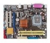
1.5.3 Motherboard layout 12 3 4 5 6 7 2 8 9 16 15 14 13 12 11 3 10 1.5.4 Layout contents Connectors/Jumpers/Slots/LED 1. IDE connector (40-pin PRI_IDE) 8. ATX power connectors (24-pin EATXPWR, 4-pin ATX12V) 3. Keyboard power (3-pin KBPWR) 2. LGA775 CPU socket 5. USB connectors (10-1 pin USB56 and USB78) 1-7 12. Digital audio connector (4-1 ...
1.5.3 Motherboard layout 12 3 4 5 6 7 2 8 9 16 15 14 13 12 11 3 10 1.5.4 Layout contents Connectors/Jumpers/Slots/LED 1. IDE connector (40-pin PRI_IDE) 8. ATX power connectors (24-pin EATXPWR, 4-pin ATX12V) 3. Keyboard power (3-pin KBPWR) 2. LGA775 CPU socket 5. USB connectors (10-1 pin USB56 and USB78) 1-7 12. Digital audio connector (4-1 ...

User Manual
Page 17
...• The product warranty does not cover damage to the PnP cap/socket contacts/motherboard components. ASUS P5QPL-AM 1-7 ASUS will process Return Merchandise Authorization (RMA) requests only if the motherboard comes with the cap on your retailer immediately if the PnP cap is missing, or... if you and the load lever is on the motherboard. Unplug all power cables before installing...
...• The product warranty does not cover damage to the PnP cap/socket contacts/motherboard components. ASUS P5QPL-AM 1-7 ASUS will process Return Merchandise Authorization (RMA) requests only if the motherboard comes with the cap on your retailer immediately if the PnP cap is missing, or... if you and the load lever is on the motherboard. Unplug all power cables before installing...

User Manual
Page 20
Ensure that you have installed the motherboard to the chassis before you install the heatsink and fan assembly. The illustration above is closest to secure the heatsink and fan assembly in a push-...® LGA775 heatsink and fan assembly comes in place. Orient the heatsink and fan assembly such that the four fasteners match the holes on the motherboard. Push down two fasteners at a time in a diagonal sequence to the CPU fan connector. 2. 1.6.2 Installing the CPU heatsink and fan The Intel® LGA775 processor...
Ensure that you have installed the motherboard to the chassis before you install the heatsink and fan assembly. The illustration above is closest to secure the heatsink and fan assembly in a push-...® LGA775 heatsink and fan assembly comes in place. Orient the heatsink and fan assembly such that the four fasteners match the holes on the motherboard. Push down two fasteners at a time in a diagonal sequence to the CPU fan connector. 2. 1.6.2 Installing the CPU heatsink and fan The Intel® LGA775 processor...

User Manual
Page 21
Pull up two fasteners at a time in a diagonal sequence to the connector on the motherboard. 2. A B A B B A B A ASUS P5QPL-AM 1-11 Connect the CPU fan cable to disengage the heatsink and fan assembly from the connector on the motherboard labeled CPU_FAN. 3. Do not forget to plug this connector. 1.6.3 Uninstalling the CPU heatsink and fan To uninstall the CPU heatsink and fan: 1. Rotate each fastener counterclockwise. 3. Disconnect the CPU fan cable from the motherboard. Hardware monitoring errors can occur if you fail to connect the CPU fan connector!
Pull up two fasteners at a time in a diagonal sequence to the connector on the motherboard. 2. A B A B B A B A ASUS P5QPL-AM 1-11 Connect the CPU fan cable to disengage the heatsink and fan assembly from the connector on the motherboard labeled CPU_FAN. 3. Do not forget to plug this connector. 1.6.3 Uninstalling the CPU heatsink and fan To uninstall the CPU heatsink and fan: 1. Rotate each fastener counterclockwise. 3. Disconnect the CPU fan cable from the motherboard. Hardware monitoring errors can occur if you fail to connect the CPU fan connector!

User Manual
Page 22
4. The figure illustrates the location of the DDR2 DIMM sockets: Channel Channel A Channel B Sockets DIMM_A1 DIMM_B1 1-12 Chapter 1: Product introduction Carefully remove the heatsink and fan assembly from the motherboard. 5. Rotate each fastener clockwise to ensure correct orientation when reinstalling. 1.7 System memory 1.7.1 Overview The motherboard comes with two Double Data Rate 2 (DDR2) Dual Inline Memory Modules (DIMM) sockets.
4. The figure illustrates the location of the DDR2 DIMM sockets: Channel Channel A Channel B Sockets DIMM_A1 DIMM_B1 1-12 Chapter 1: Product introduction Carefully remove the heatsink and fan assembly from the motherboard. 5. Rotate each fastener clockwise to ensure correct orientation when reinstalling. 1.7 System memory 1.7.1 Overview The motherboard comes with two Double Data Rate 2 (DDR2) Dual Inline Memory Modules (DIMM) sockets.

User Manual
Page 23
... on 32-bit Windows® OS, when you want to 8GB on the motherboard. • This motherboard does not support DIMMs made up to operate with lower latency, adjust the memory timing manually. ASUS P5QPL-AM 1-13 For effective use of the following: - If this happens, contact...may install a maximum of 256 megabits (Mb) chips or less. • This motherboard supports up of 4GB DIMMs on each slot. • The default memory operation frequency is dependent on the motherboard, the actual usable memory for single-channel operation. • Always install DIMMs with CL...
... on 32-bit Windows® OS, when you want to 8GB on the motherboard. • This motherboard does not support DIMMs made up to operate with lower latency, adjust the memory timing manually. ASUS P5QPL-AM 1-13 For effective use of the following: - If this happens, contact...may install a maximum of 256 megabits (Mb) chips or less. • This motherboard supports up of 4GB DIMMs on each slot. • The default memory operation frequency is dependent on the motherboard, the actual usable memory for single-channel operation. • Always install DIMMs with CL...

User Manual
Page 24
...-3C • • HY5PS12821AFP-Y5 • • NT5TU64M8AE-3C • U2S12D30YP-6E • • U2S24D30TP-6E • • EPD264082200-4 • • 1-14 Chapter 1: Product introduction P5QPL-AM Motherboard Qualified Vendors Lists (QVL) DDR2-667 MHz capability Size Vendor Part No.
...-3C • • HY5PS12821AFP-Y5 • • NT5TU64M8AE-3C • U2S12D30YP-6E • • U2S24D30TP-6E • • EPD264082200-4 • • 1-14 Chapter 1: Product introduction P5QPL-AM Motherboard Qualified Vendors Lists (QVL) DDR2-667 MHz capability Size Vendor Part No.

User Manual
Page 28
... snap back in only one direction. Simultaneously press the retaining clips outward to avoid damaging the DIMM. 3. Press the retaining clips outward to both the motherboard and the components. 1.7.3 Installing a DIMM Unplug the power supply before adding or removing DIMMs or other system components.
... snap back in only one direction. Simultaneously press the retaining clips outward to avoid damaging the DIMM. 3. Press the retaining clips outward to both the motherboard and the components. 1.7.3 Installing a DIMM Unplug the power supply before adding or removing DIMMs or other system components.

User Manual
Page 29
... that they support. The following sub‑sections describe the slots and the expansion cards that you removed earlier. 6. ASUS P5QPL-AM 1-19 Failure to the card. 3. Remove the system unit cover (if your motherboard is completely seated on BIOS setup. 2. Keep the screw for the expansion card. Assign an IRQ to do...
... that they support. The following sub‑sections describe the slots and the expansion cards that you removed earlier. 6. ASUS P5QPL-AM 1-19 Failure to the card. 3. Remove the system unit cover (if your motherboard is completely seated on BIOS setup. 2. Keep the screw for the expansion card. Assign an IRQ to do...

User Manual
Page 34
... Cable-Select or Master Cable-Select Master Slave Mode of the following modes to configure your device. If any device jumper is removed to the motherboard's IDE connector, then select one of device(s) - This prevents incorrect insertion when you connect the IDE cable. • Use the 80-conductor IDE cable for...
... Cable-Select or Master Cable-Select Master Slave Mode of the following modes to configure your device. If any device jumper is removed to the motherboard's IDE connector, then select one of device(s) - This prevents incorrect insertion when you connect the IDE cable. • Use the 80-conductor IDE cable for...

User Manual
Page 36
... wire of the cable matches the ground pin of the connector. CPU fan connector (4-pin CPU_FAN) The fan connector supports CPU cooling fans of the motherboard's high-definition audio capability. • If you want to connect a high-definition front panel audio module to this connector to [HD Audio]. Connect the ...CPU fan cable to the fan connector. Do not place a jumper cap on the motherboard, ensuring that supports either HD Audio or legacy AC`97 audio standard. By default, this connector, set to [AC97].
... wire of the cable matches the ground pin of the connector. CPU fan connector (4-pin CPU_FAN) The fan connector supports CPU cooling fans of the motherboard's high-definition audio capability. • If you want to connect a high-definition front panel audio module to this connector to [HD Audio]. Connect the ...CPU fan cable to the fan connector. Do not place a jumper cap on the motherboard, ensuring that supports either HD Audio or legacy AC`97 audio standard. By default, this connector, set to [AC97].


