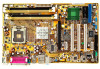
P5PL2 User's Manual for English Edition
Page 3
Contents Notices vi Safety information vii About this guide viii P5PL2 specifications summary x Chapter 1: Product introduction 1.1 Welcome 1-1 1.2 Package contents 1-1 1.3 Special features 1-2 1.3.1 Product highlights 1-2 1.3.2 Innovative ASUS features 1-3 Chapter 2: Hardware information 2.1 Before you proceed 2-1 2.2 Motherboard overview 2-2 2.2.1 Placement direction 2-2 2.2.2 Screw holes 2-2 2.2.3 Motherboard layout 2-3 2.2.4 Layout contents 2-4 2.3 Central Processing Unit (CPU 2-6 2.3.1 Installing the CPU 2-6 2.3.2 Installing the CPU heatsink...
P5PL2 User's Manual for English Edition
Page 7
...are not sure about the voltage of the electrical outlet you add a device. • Before connecting or removing signal cables from the motherboard, ensure that all power cables are not damaged. If you encounter technical problems with the package. • Before using the product, ...possible, disconnect all the manuals that came with the product, contact a qualified service technician or your retailer. Operation safety • Before installing the motherboard and adding devices on a stable surface. • If you detect any area where it may become wet. • Place the product on...
P5PL2 User's Manual for English Edition
Page 8
... Setup menus. Optional documentation Your product package may have to the ASUS contact information. 2. viii It includes description of the standard package. ASUS websites The ASUS website provides updated information on the motherboard. • Chapter 3: Powering up This chapter describes the power ...software updates. 1. These documents are also provided. • Chapter 5: Software support This chapter describes the contents of the motherboard and the new technology it supports. • Chapter 2: Hardware information This chapter lists the hardware setup procedures that you ...
P5PL2 User's Manual for English Edition
Page 13
This chapter describes the motherboard features and the new technologies it supports. 1Product introduction
P5PL2 User's Manual for English Edition
Page 15
... long line of the above items is damaged or missing, contact your retailer. Before you for the following items. Motherboard ASUS P5PL2 motherboard I /O shield Application CDs ASUS motherboard support CD Documentation User guide If any of ASUS quality motherboards! ASUS P5PL2 1-1 The motherboard delivers a host of new features and latest technologies, making it , check the items in your package with the...
P5PL2 User's Manual for English Edition
Page 16
...capability. 64-bit CPU support 64-bit computing, the next generation technology to 300 MB/s data transfer rate. Serial ATA technology The motherboard supports the Serial ATA technology through the Serial ATA interfaces. Dual Channel DDRII 533 DDR2 is one of 400 and 533MHz, DDR2 memory...Core CPU Enjoy the extraordinary CPU power from Intel in LGA775 package. 1.3 Special features 1.3.1 Product highlights Intel® LGA775 Pentium 4 CPU This motherboard supports the latest Pentium 4 CPU from the latest dual-core CPU. With 800/533MHz FSB, Hyper-Threading Technology and corespeeds up to 3.8GHz ...
P5PL2 User's Manual for English Edition
Page 17
... the BIOS default settings in the motherboard allows you to adjust the CPU multiplier to restore the original BIOS data from the support CD in packets. Simply shut down and reboot the system, and the BIOS automatically restores the CPU default setting for each parameter. ASUS P5PL2 1-3 S/PDIF-out on Back I /O interconnect technology...
P5PL2 User's Manual for English Edition
Page 19
It includes description of the jumpers and connectors on the motherboard. 2 Hardware information This chapter lists the hardware setup procedures that you have to perform when installing system components.
P5PL2 User's Manual for English Edition
Page 20
Chapter summary 2 2.1 Before you proceed 2-1 2.2 Motherboard overview 2-2 2.3 Central Processing Unit (CPU 2-6 2.4 System memory 2-13 2.5 Expansion slots 2-16 2.6 Jumpers 2-19 2.7 Connectors 2-21 ASUS P5PL2
P5PL2 User's Manual for English Edition
Page 21
... illustration below shows the location of the following precautions before you install motherboard components or change any motherboard settings. • Unplug the power cord from the wall socket before touching any motherboard component. P5PL2 R P5PL2 Onboard LED SB_PWR ON Standby Power OFF Powered Off ASUS P5PL2 2-1 2.1 Before you proceed Take note of the onboard LED. Failure to...
P5PL2 User's Manual for English Edition
Page 22
Place this side towards the rear of the chassis R P5PL2 2-2 Chapter 2: Hardware information Make sure to the chassis. Do not overtighten the screws! Doing so can cause you place it . Failure to do so can damage the motherboard. The edge with external ports goes to the rear part of the ...chassis as indicated in the image below. 2.2.2 Screw holes Place seven (7) screws into the chassis in the correct orientation. 2.2 Motherboard overview Before you install the motherboard, study the configuration of your chassis to ensure that you physical injury and damage...
P5PL2 User's Manual for English Edition
Page 26
...the load lever is shipment/ transit-related. • Keep the cap after installing the motherboard. ASUS will shoulder the cost of the PnP cap. 2.3.1 Installing the CPU To install a CPU: 1. R P5PL2 CPU Socket 775 Before installing the CPU, make sure that the cam box is on ...socket. • The product warranty does not cover damage to the PnP cap/socket contacts/motherboard components. Contact your left. ASUS will process Return Merchandise Authorization (RMA) requests only if the motherboard comes with a surface mount LGA775 socket designed for the Intel® Pentium® 4 ...
P5PL2 User's Manual for English Edition
Page 28
Refer to prevent bending the connectors on these CPU features. 2-8 Chapter 2: Hardware information DO NOT force the CPU into the retention tab. B The motherboard supports Intel® Pentium® 4 LGA775 processors with the Intel® Enhanced Memory 64 Technology (EM64T), Enhanced Intel SpeedStep® Technology (EIST), and Hyper-Threading Technology. Close the load plate (A), then A push the load lever (B) until it snaps into the socket to the Appendix for more information on the socket and damaging the CPU! 6. The CPU fits in only one correct orientation.
P5PL2 User's Manual for English Edition
Page 29
... • If you purchased a separate CPU heatsink and fan assembly, make sure that you have installed the motherboard to the chassis before you install the heatsink and fan assembly. If you install the CPU fan and heatsink ... the CPU fan and heatsink assembly. To install the CPU heatsink and fan: 1. Narrow end of the groove Motherboard hole Fastener Make sure to the CPU fan connector. Make sure that the CPU fan cable is closest to orient...the groove pointing outward. (The photo shows the groove shaded for emphasis.) ASUS P5PL2 2-9 Place the heatsink on the motherboard.
P5PL2 User's Manual for English Edition
Page 30
Connect the CPU fan cable to plug this connector. 2-10 Chapter 2: Hardware information Hardware monitoring errors can occur if you fail to the connector on the motherboard labeled CPU_FAN. CPU_FAN GND CPU FAN PWR CPU FAN IN CPU FAN PWM R P5PL2 P5PL2 CPU Fan Connectors Do not forget to secure the heatsink and fan B assembly in a diagonal sequence to connect the CPU fan connector! 2. Push down two fasteners at a time in place. A A A B B B A 3.
P5PL2 User's Manual for English Edition
Page 31
Pull up two fasteners at a time in a diagonal sequence to disengage the heatsink and fan assembly from the motherboard. B A B ASUS P5PL2 2-11 A B B A 4. Carefully remove the heatsink and fan assembly from the A motherboard. Disconnect the CPU fan cable from the connector on the motherboard. 2. 2.3.3 Uninstalling the CPU heatsink and fan To uninstall the CPU heatsink and fan: 1. Rotate each fastener counterclockwise. 3.
P5PL2 User's Manual for English Edition
Page 33
...DIMM) sockets. Refer to the 184-pin DDR DIMM. The figure illustrates the location of the DDR2 DIMM sockets: 112 pins P5PL2 128 pins DIMM_A1 DIMM_A2 R DIMM_B1 DIMM_B2 P5PL2 240-pin DDR2 DIMM sockets Channel Channel A Channel B Sockets DIMM_A1 and DIMM_A2 DIMM_B1 and DIMM_B2 2.4.2 Memory configurations You may install 128...Qualified Vendors List on a DDR DIMM socket. For optimum compatibility, it is recommended that you obtain memory modules from the same vendor. ASUS P5PL2 2-13 2.4 System memory 2.4.1 Overview The motherboard comes with the same CAS latency.
P5PL2 User's Manual for English Edition
Page 35
...notch so that the notch on the DIMM matches the break on 1 the socket. 3. Simultaneously press the retaining clips outward to both the motherboard and the components. 2.4.3 Installing a DIMM Unplug the power supply before adding or removing DIMMs or other system components. Firmly insert the DIMM... sockets do so can cause severe damage to unlock the DIMM. The DIMM might get damaged when it fits in only one direction. ASUS P5PL2 2-15 Support the DIMM lightly with extra force. 2 1 DDR2 DIMM notch 2. Unlock a DIMM socket by pressing 3 the retaining clips outward...