User Manual
Page 4
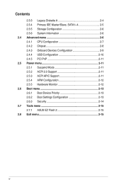
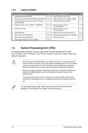
Contents 2.3.3 Legacy Diskette A 2-4 2.3.4 Primary IDE Master/Slave, SATA1~4 2-5 2.3.5 Storage Configuration 2-6 2.3.6 System Information 2-6 2.4 Advanced menu 2-6 2.4.1 CPU Configuration 2-7 2.4.2 Chipset 2-8 2.4.3 Onboard Devices Configuration 2-9 2.4.4 USB Configuration 2-10 2.4.5 PCI PnP 2-11 2.5 Power menu 2-11 2.5.1 Suspend Mode 2-11 2.5.2 ACPI 2.0 Support 2-11 2.5.3 ACPI APIC Support 2-11 2.5.4 APM Configuration 2-12 2.5.5 Hardware Monitor 2-12 2.6 Boot ...
Contents 2.3.3 Legacy Diskette A 2-4 2.3.4 Primary IDE Master/Slave, SATA1~4 2-5 2.3.5 Storage Configuration 2-6 2.3.6 System Information 2-6 2.4 Advanced menu 2-6 2.4.1 CPU Configuration 2-7 2.4.2 Chipset 2-8 2.4.3 Onboard Devices Configuration 2-9 2.4.4 USB Configuration 2-10 2.4.5 PCI PnP 2-11 2.5 Power menu 2-11 2.5.1 Suspend Mode 2-11 2.5.2 ACPI 2.0 Support 2-11 2.5.3 ACPI APIC Support 2-11 2.5.4 APM Configuration 2-12 2.5.5 Hardware Monitor 2-12 2.6 Boot ...
User Manual
Page 8
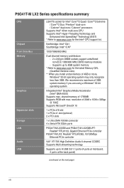
... P5G41T-M LX2/GB/LPT: Realtek® RTL8112L Gigabit Ethernet PCIe controller P5G41T-M LX2: Realtek® RTL8103EL 10/100Mbps Ethernet PCIe controller VIA® VT1705 High Definition Audio 6-channel CODEC Supports Multi-streaming technology Supports up to 8GB system memory * Refer to www.asus.com for...Integrated Intel® Graphics Media Accelerator (Intel® GMA 4500) Supports max. P5G41T-M LX2 Series specifications summary CPU Chipset Front Side Bus Memory Graphics Expansion slots Storage LAN Audio USB LGA775 socket for Intel® Core™2 Quad / Core™2 Extreme / Core&#...
... P5G41T-M LX2/GB/LPT: Realtek® RTL8112L Gigabit Ethernet PCIe controller P5G41T-M LX2: Realtek® RTL8103EL 10/100Mbps Ethernet PCIe controller VIA® VT1705 High Definition Audio 6-channel CODEC Supports Multi-streaming technology Supports up to 8GB system memory * Refer to www.asus.com for...Integrated Intel® Graphics Media Accelerator (Intel® GMA 4500) Supports max. P5G41T-M LX2 Series specifications summary CPU Chipset Front Side Bus Memory Graphics Expansion slots Storage LAN Audio USB LGA775 socket for Intel® Core™2 Quad / Core™2 Extreme / Core&#...
User Manual
Page 9
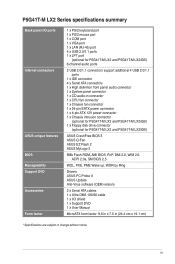
... specifications summary Back panel I/O ports Internal connectors ASUS unique features BIOS Manageability Support DVD Accessories Form factor 1 x PS/2 keyboard port 1 x PS/2 mouse port 1 x COM port 1 x VGA port 1 x LAN (RJ-45) port 4 x USB 2.0/1.1 ports 1 x LPT port (optional for P5G41T-M LX2 and P5G41T-M LX2/GB) 6-channel audio ports 2 USB 2.0/1.1 connectors support additional 4 USB 2.0/1.1 ports 1 x IDE connector 4 x Serial ATA connectors 1 x High...
... specifications summary Back panel I/O ports Internal connectors ASUS unique features BIOS Manageability Support DVD Accessories Form factor 1 x PS/2 keyboard port 1 x PS/2 mouse port 1 x COM port 1 x VGA port 1 x LAN (RJ-45) port 4 x USB 2.0/1.1 ports 1 x LPT port (optional for P5G41T-M LX2 and P5G41T-M LX2/GB) 6-channel audio ports 2 USB 2.0/1.1 connectors support additional 4 USB 2.0/1.1 ports 1 x IDE connector 4 x Serial ATA connectors 1 x High...
User Manual
Page 12
...the PnP cap/socket contacts/motherboard components. ATX power connectors (24-pin EATXPWR, 4-pin ATX12V) 3. USB connectors (10-1 pin USB56, USB78) 1-11 12. Standby power LED (SB_PWR) 1-8 13. USB device wake-up (3-pin USBPW1-4, USBPW5-8) 5. System panel connector (10-1 pin F_PANEL) Page Connectors... Unit (CPU) This motherboard comes with the Intel® Enhanced Intel SpeedStep® Technology (EIST) and Hyper-Threading Technology. 1-3 ASUS P5G41T-M LX2 Series DDR3 DIMM slots 7. Front panel audio connector (10-1 pin AAFP) 1-11 17. Chassis intrusion connector (4-1 pin CHASSIS) 1-3 14...
...the PnP cap/socket contacts/motherboard components. ATX power connectors (24-pin EATXPWR, 4-pin ATX12V) 3. USB connectors (10-1 pin USB56, USB78) 1-11 12. Standby power LED (SB_PWR) 1-8 13. USB device wake-up (3-pin USBPW1-4, USBPW5-8) 5. System panel connector (10-1 pin F_PANEL) Page Connectors... Unit (CPU) This motherboard comes with the Intel® Enhanced Intel SpeedStep® Technology (EIST) and Hyper-Threading Technology. 1-3 ASUS P5G41T-M LX2 Series DDR3 DIMM slots 7. Front panel audio connector (10-1 pin AAFP) 1-11 17. Chassis intrusion connector (4-1 pin CHASSIS) 1-3 14...
User Manual
Page 15
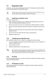
... the two PCI groups, making the system unstable and the card inoperable. 1.5.3 PCI slots The PCI slot supports cards such as a LAN card, SCSI card, USB card, and other cards that comply with the PCI Express specifications. Assign an IRQ to install expansion cards. Chapter 1: Product introduction 1-6 Remove the system unit...
... the two PCI groups, making the system unstable and the card inoperable. 1.5.3 PCI slots The PCI slot supports cards such as a LAN card, SCSI card, USB card, and other cards that comply with the PCI Express specifications. Assign an IRQ to install expansion cards. Chapter 1: Product introduction 1-6 Remove the system unit...
User Manual
Page 17
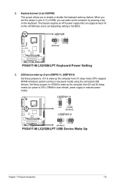
KBPWR 12 23 +5V +5VSB (Default) P5G41T-M LX2/GB/LPT P5G41T-M LX2/GB/LPT Keyboard Power Setting 3. When you set this jumper to pins... Keyboard power (3-pin KBPWR) This jumper allows you can supply at least 1A on the keyboard. USB device wake-up (3-pin USBPW1-4, USBPW5-8) Set these jumpers to +5VSB to wake up the computer ...system running in reduced power mode). USBPW1-4 12 23 +5V +5VSB (Default) USBPW5-8 P5G41T-M LX2/GB/LPT 12 23 +5V +5VSB (Default) P5G41T-M LX2/GB/LPT USB Device Wake Up Chapter 1: Product introduction 1-8 2. Set these jumpers to +5V to CPU, DRAM...
KBPWR 12 23 +5V +5VSB (Default) P5G41T-M LX2/GB/LPT P5G41T-M LX2/GB/LPT Keyboard Power Setting 3. When you set this jumper to pins... Keyboard power (3-pin KBPWR) This jumper allows you can supply at least 1A on the keyboard. USB device wake-up (3-pin USBPW1-4, USBPW5-8) Set these jumpers to +5VSB to wake up the computer ...system running in reduced power mode). USBPW1-4 12 23 +5V +5VSB (Default) USBPW5-8 P5G41T-M LX2/GB/LPT 12 23 +5V +5VSB (Default) P5G41T-M LX2/GB/LPT USB Device Wake Up Chapter 1: Product introduction 1-8 2. Set these jumpers to +5V to CPU, DRAM...

User Manual
Page 19
... Standby +5 Volts Power OK -5 Volts PIN 1 GND +5 Volts GND GND GND GND GND GND P5G41T-M LX2/GB/LPT +5 Volts GND PSON# GND +3 Volts -12 Volts +3 Volts +3 Volts PIN 1 P5G41T-M LX2/GB/LPT ATX power connectors • For a fully configured system, we recommend that you use a power supply unit ... In 6-channel Rear Speaker Out Front Speaker Out Bass/Center 7. USB 2.0 ports 1 and 2. These two 4-pin Universal Serial Bus (USB) ports are designed to the Recommended Power Supply Wattage Calculator at http://support.asus. Video Graphics Adapter (VGA) port. PS/2 keyboard port (purple...
... Standby +5 Volts Power OK -5 Volts PIN 1 GND +5 Volts GND GND GND GND GND GND P5G41T-M LX2/GB/LPT +5 Volts GND PSON# GND +3 Volts -12 Volts +3 Volts +3 Volts PIN 1 P5G41T-M LX2/GB/LPT ATX power connectors • For a fully configured system, we recommend that you use a power supply unit ... In 6-channel Rear Speaker Out Front Speaker Out Bass/Center 7. USB 2.0 ports 1 and 2. These two 4-pin Universal Serial Bus (USB) ports are designed to the Recommended Power Supply Wattage Calculator at http://support.asus. Video Graphics Adapter (VGA) port. PS/2 keyboard port (purple...
User Manual
Page 22
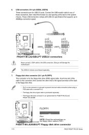
... when using a FDD cable with USB 2.0 specification that supports up to the USB connectors. USB+5V USB_P8USB_P8+ GND NC USB+5V USB_P6USB_P6+ GND NC P5G41T-M LX2/GB/LPT USB56 PIN 1 USB78 PIN 1 USB+5V USB_P7USB_P7+ GND USB+5V USB_P5USB_P5+ GND P5G41T-M LX2/GB/LPT USB2.0 connectors Never connect a 1394 cable to 480Mbps connection speed. P5G41T-M LX2/GB/LPT Floppy disk drive connector 1-13 ASUS P5G41T-M LX2 Series
... when using a FDD cable with USB 2.0 specification that supports up to the USB connectors. USB+5V USB_P8USB_P8+ GND NC USB+5V USB_P6USB_P6+ GND NC P5G41T-M LX2/GB/LPT USB56 PIN 1 USB78 PIN 1 USB+5V USB_P7USB_P7+ GND USB+5V USB_P5USB_P5+ GND P5G41T-M LX2/GB/LPT USB2.0 connectors Never connect a 1394 cable to 480Mbps connection speed. P5G41T-M LX2/GB/LPT Floppy disk drive connector 1-13 ASUS P5G41T-M LX2 Series
User Manual
Page 26
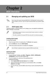
...from the Internet, then click Next. Follow the onscreen instructions to download then click Next. 2-1 ASUS P5G41T-M LX2 Series From the dropdown list, select any of the original motherboard BIOS file to a USB flash disk in the future. b. Updating the BIOS To update the BIOS: 1. Click the ...Utilities tab, then click ASUS Update. 3. Quit all Windows® applications before you to restore the...
...from the Internet, then click Next. Follow the onscreen instructions to download then click Next. 2-1 ASUS P5G41T-M LX2 Series From the dropdown list, select any of the original motherboard BIOS file to a USB flash disk in the future. b. Updating the BIOS To update the BIOS: 1. Click the ...Utilities tab, then click ASUS Update. 3. Quit all Windows® applications before you to restore the...
User Manual
Page 27
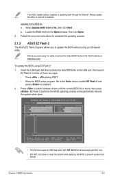
... a BIOS file a. b. Press to prevent system boot failure! ASUSTek EZ Flash 2 BIOS ROM Utility V3.44 FLASH TYPE: MXIC 25L8005 Current ROM BOARD:P5G41T-M LX2/GB/LPT VER:0305 (H:00 B:00) DATE: 10/29/2009 Update ROM BOARD: Unknown VER: Unknown DATE: Unknown PATH: A:\ A: Note [Enter] Select or Load [... itself through the Internet. Insert the USB flash disk that contains the latest BIOS file to update the BIOS without using an OS‑based utility. EZ Flash 2 performs the BIOS updating process and automatically reboots the system when done. The ASUS Update utility is found, then press ...
... a BIOS file a. b. Press to prevent system boot failure! ASUSTek EZ Flash 2 BIOS ROM Utility V3.44 FLASH TYPE: MXIC 25L8005 Current ROM BOARD:P5G41T-M LX2/GB/LPT VER:0305 (H:00 B:00) DATE: 10/29/2009 Update ROM BOARD: Unknown VER: Unknown DATE: Unknown PATH: A:\ A: Note [Enter] Select or Load [... itself through the Internet. Insert the USB flash disk that contains the latest BIOS file to update the BIOS without using an OS‑based utility. EZ Flash 2 performs the BIOS updating process and automatically reboots the system when done. The ASUS Update utility is found, then press ...
User Manual
Page 28
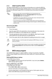
...and brief online help to guide you do not press , POST continues with motherboard models. Download the latest BIOS file from the ASUS website at startup: • Press during the updating process. The utility automatically checks the devices for details. 2.2 BIOS setup ... (POST). For motherboards without the floppy connector, prepare a USB flash disk before using this utility, rename the BIOS file in the removable device into PG41TML2.ROM (P5G41T-M LX2) / PG41TMLG.ROM (P5G41T-M LX2/GB) / PG41TMLP.ROM (P5G41T-M LX2/GB/LPT). • The BIOS file in using the BIOS Setup program...
...and brief online help to guide you do not press , POST continues with motherboard models. Download the latest BIOS file from the ASUS website at startup: • Press during the updating process. The utility automatically checks the devices for details. 2.2 BIOS setup ... (POST). For motherboards without the floppy connector, prepare a USB flash disk before using this utility, rename the BIOS file in the removable device into PG41TML2.ROM (P5G41T-M LX2) / PG41TMLG.ROM (P5G41T-M LX2/GB) / PG41TMLP.ROM (P5G41T-M LX2/GB/LPT). • The BIOS file in using the BIOS Setup program...
User Manual
Page 31
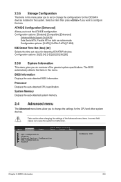
... to configure the item. Configuration options: [S-ATA] [S-ATA+P-ATA] [P-ATA]. Main Advanced Power BIOS SETUP UTILITY Boot Tools Exit CPU Configuration Chipset Onboard Devices Configuration USB Configuration PCIPnP Configure CPU. Chapter 2: BIOS information 2-6 IDE Detect Time Out (Sec) [35] Selects the time out value for the CPU and other system devices...
... to configure the item. Configuration options: [S-ATA] [S-ATA+P-ATA] [P-ATA]. Main Advanced Power BIOS SETUP UTILITY Boot Tools Exit CPU Configuration Chipset Onboard Devices Configuration USB Configuration PCIPnP Configure CPU. Chapter 2: BIOS information 2-6 IDE Detect Time Out (Sec) [35] Selects the time out value for the CPU and other system devices...
User Manual
Page 35
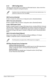
...[Disabled] [Enabled] USB 2.0 Controller [Enabled] Enables or disables USB 2.0 controller. Setting this menu allows you to set the maximum time that the BIOS waits for Legacy USB storage devices, including USB flash drives and USB hard drives. If detected, the USB controller legacy mode is ...plugged in. Configuration options: [FullSpeed] [HiSpeed] The following items only appear when a USB storage device is enabled. Configuration options:...
...[Disabled] [Enabled] USB 2.0 Controller [Enabled] Enables or disables USB 2.0 controller. Setting this menu allows you to set the maximum time that the BIOS waits for Legacy USB storage devices, including USB flash drives and USB hard drives. If detected, the USB controller legacy mode is ...plugged in. Configuration options: [FullSpeed] [HiSpeed] The following items only appear when a USB storage device is enabled. Configuration options:...


