User Manual
Page 3
... an expansion card 1-6 1.5.3 PCI slots 1-6 1.5.4 PCI Express x16 slot 1-6 1.6 Jumpers 1-7 1.7 Connectors 1-9 1.7.1 Rear panel ports 1-9 1.7.2 Internal connectors 1-10 1.8 Software support 1-16 1.8.1 Installing an operating system 1-16 1.8.2 Support DVD information 1-16 Chapter 2: BIOS information 2.1 Managing and updating your BIOS 2-1 2.1.1 ASUS Update utility 2-1 2.1.2 ASUS EZ Flash 2 2-2 2.1.3 ASUS CrashFree BIOS 2-3 2.2 BIOS setup program 2-3 2.3 Main menu 2-4 2.3.1 System Time 2-4 2.3.2 System Date...
... an expansion card 1-6 1.5.3 PCI slots 1-6 1.5.4 PCI Express x16 slot 1-6 1.6 Jumpers 1-7 1.7 Connectors 1-9 1.7.1 Rear panel ports 1-9 1.7.2 Internal connectors 1-10 1.8 Software support 1-16 1.8.1 Installing an operating system 1-16 1.8.2 Support DVD information 1-16 Chapter 2: BIOS information 2.1 Managing and updating your BIOS 2-1 2.1.1 ASUS Update utility 2-1 2.1.2 ASUS EZ Flash 2 2-2 2.1.3 ASUS CrashFree BIOS 2-3 2.2 BIOS setup program 2-3 2.3 Main menu 2-4 2.3.1 System Time 2-4 2.3.2 System Date...

User Manual
Page 6
... damage, contact your retailer. Contact a qualified service technician or your dealer immediately. • To avoid short circuits, keep paper clips, screws, and staples away from connectors, slots, sockets and circuitry. • Avoid dust, humidity, and temperature extremes. Operation safety • Before installing the motherboard and adding devices on a stable surface. •...
... damage, contact your retailer. Contact a qualified service technician or your dealer immediately. • To avoid short circuits, keep paper clips, screws, and staples away from connectors, slots, sockets and circuitry. • Avoid dust, humidity, and temperature extremes. Operation safety • Before installing the motherboard and adding devices on a stable surface. •...
User Manual
Page 8
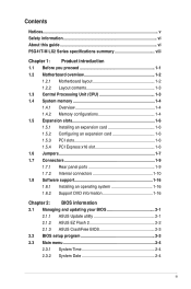
... 1 x PCIe x1 slot (optional) 2 x PCI slots 1 x Ultra DMA 100/66 connector 4 x Serial ATA 3Gb/s ports P5G41T-M LX2/GB and P5G41T-M LX2/GB/LPT: Realtek® RTL8112L Gigabit Ethernet PCIe controller P5G41T-M LX2: Realtek® RTL8103EL 10/100Mbps Ethernet PCIe controller VIA® VT1705 High Definition Audio 6-channel ...; 45nm multi-core CPU Supports Intel® Hyper-Threading Technology and Enhanced Intel SpeedStep® Technology (EIST) * Refer to www.asus.com for the latest Memory QVL (Qualified Vendors Lists). ** When you are using a Windows® 32-bit operating system. Northbridge...
... 1 x PCIe x1 slot (optional) 2 x PCI slots 1 x Ultra DMA 100/66 connector 4 x Serial ATA 3Gb/s ports P5G41T-M LX2/GB and P5G41T-M LX2/GB/LPT: Realtek® RTL8112L Gigabit Ethernet PCIe controller P5G41T-M LX2: Realtek® RTL8103EL 10/100Mbps Ethernet PCIe controller VIA® VT1705 High Definition Audio 6-channel ...; 45nm multi-core CPU Supports Intel® Hyper-Threading Technology and Enhanced Intel SpeedStep® Technology (EIST) * Refer to www.asus.com for the latest Memory QVL (Qualified Vendors Lists). ** When you are using a Windows® 32-bit operating system. Northbridge...
User Manual
Page 9
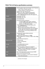
... Back panel I/O ports Internal connectors ASUS unique features BIOS Manageability Support DVD Accessories Form factor 1 x PS/2 keyboard port 1 x PS/2 mouse port 1 x COM port 1 x VGA port 1 x LAN (RJ-45) port 4 x USB 2.0/1.1 ports 1 x LPT port (optional for P5G41T-M LX2 and P5G41T-M LX2/GB) 6-channel audio ports 2 USB 2.0/1.1 connectors support additional 4 USB 2.0/1.1 ports 1 x IDE connector 4 x Serial ATA connectors 1 x High definition front panel...
... Back panel I/O ports Internal connectors ASUS unique features BIOS Manageability Support DVD Accessories Form factor 1 x PS/2 keyboard port 1 x PS/2 mouse port 1 x COM port 1 x VGA port 1 x LAN (RJ-45) port 4 x USB 2.0/1.1 ports 1 x LPT port (optional for P5G41T-M LX2 and P5G41T-M LX2/GB) 6-channel audio ports 2 USB 2.0/1.1 connectors support additional 4 USB 2.0/1.1 ports 1 x IDE connector 4 x Serial ATA connectors 1 x High definition front panel...
User Manual
Page 11
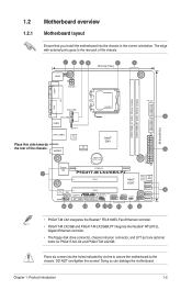
...Intel® G41 Lithium Cell CMOS Power PRI_IDE 7 2 24.4cm(9.6in) EATXPWR Super PCIEX16 I/O 17 P5G41T-M LX2/GB/LPT SATA4 SATA3 8Mb PCI1 Intel® SATA2 BIOS SATA1 ICH7 PCI2 8 VIA VT1705 CD FLOPPY SB_PWR USBPW5-8 USB56 ...• P5G41T-M LX2 integrates the Realtek® RTL8103EL Fast Ethernet controller. • P5G41T-M LX2/GB and P5G41T-M LX2/GB/LPT integrate the Realtek® RTL8112L Gigabit Ethernet controller. • The floppy disk drive connector, chassis intrusion connector, and LPT port are optional items for P5G41T-M LX2 and P5G41T-M LX2/GB. Place six screws...
...Intel® G41 Lithium Cell CMOS Power PRI_IDE 7 2 24.4cm(9.6in) EATXPWR Super PCIEX16 I/O 17 P5G41T-M LX2/GB/LPT SATA4 SATA3 8Mb PCI1 Intel® SATA2 BIOS SATA1 ICH7 PCI2 8 VIA VT1705 CD FLOPPY SB_PWR USBPW5-8 USB56 ...• P5G41T-M LX2 integrates the Realtek® RTL8103EL Fast Ethernet controller. • P5G41T-M LX2/GB and P5G41T-M LX2/GB/LPT integrate the Realtek® RTL8112L Gigabit Ethernet controller. • The floppy disk drive connector, chassis intrusion connector, and LPT port are optional items for P5G41T-M LX2 and P5G41T-M LX2/GB. Place six screws...
User Manual
Page 12
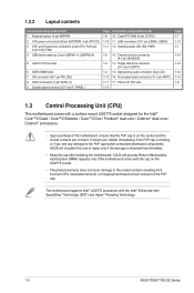
... removal of the PnP cap. IDE connector (40-1 pin PRI_IDE) 8. PCIe x16 / PCI slots 1-15 Page 1-7 1-13 1-1 1-14 1-13 1-12 1-14 1-6 1.3 Central Processing Unit (CPU) This motherboard comes with the Intel® Enhanced Intel SpeedStep® Technology (EIST) and Hyper-Threading Technology. 1-3 ASUS P5G41T-M LX2 Series 1.2.2 Layout contents Connectors/Jumpers/Slots/LED 1. Keyboard power...
... removal of the PnP cap. IDE connector (40-1 pin PRI_IDE) 8. PCIe x16 / PCI slots 1-15 Page 1-7 1-13 1-1 1-14 1-13 1-12 1-14 1-6 1.3 Central Processing Unit (CPU) This motherboard comes with the Intel® Enhanced Intel SpeedStep® Technology (EIST) and Hyper-Threading Technology. 1-3 ASUS P5G41T-M LX2 Series 1.2.2 Layout contents Connectors/Jumpers/Slots/LED 1. Keyboard power...
User Manual
Page 15
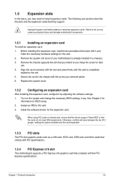
... press firmly until the card is already installed in a chassis). 3. Chapter 1: Product introduction 1-6 Turn on the slot. 5. Assign an IRQ to use . 4. Align the card connector with it by adjusting the software settings. 1. See Chapter 2 for the card. 2. When using PCI cards on BIOS setup. 2. Before installing the expansion card, read...
... press firmly until the card is already installed in a chassis). 3. Chapter 1: Product introduction 1-6 Turn on the slot. 5. Assign an IRQ to use . 4. Align the card connector with it by adjusting the software settings. 1. See Chapter 2 for the card. 2. When using PCI cards on BIOS setup. 2. Before installing the expansion card, read...
User Manual
Page 18
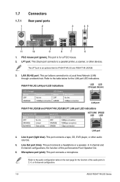
...Green) Status OFF GREEN Description No link 10Mbps connection LED LED (Orange) (Green) LAN port P5G41T-M LX2/GB and P5G41T-M LX2/GB/LPT LAN port LED indications Activity/Link LED Status Description OFF No link ORANGE Linked BLINKING Data activity Speed LED ... LED indications. In 4-channel and 6-channel configurations, the function of the audio ports in 2, 4, or 6-channel configuration. 1-9 ASUS P5G41T-M LX2 Series Line In port (light blue). 1.7 1.7.1 1 Connectors Rear panel ports 2 3 45 11 10 9 8 7 6 1. This port allows connection to a parallel printer, a scanner...
...Green) Status OFF GREEN Description No link 10Mbps connection LED LED (Orange) (Green) LAN port P5G41T-M LX2/GB and P5G41T-M LX2/GB/LPT LAN port LED indications Activity/Link LED Status Description OFF No link ORANGE Linked BLINKING Data activity Speed LED ... LED indications. In 4-channel and 6-channel configurations, the function of the audio ports in 2, 4, or 6-channel configuration. 1-9 ASUS P5G41T-M LX2 Series Line In port (light blue). 1.7 1.7.1 1 Connectors Rear panel ports 2 3 45 11 10 9 8 7 6 1. This port allows connection to a parallel printer, a scanner...

User Manual
Page 19
...Volts Power OK -5 Volts PIN 1 GND +5 Volts GND GND GND GND GND GND P5G41T-M LX2/GB/LPT +5 Volts GND PSON# GND +3 Volts -12 Volts +3 Volts +3 Volts PIN 1 P5G41T-M LX2/GB/LPT ATX power connectors • For a fully configured system, we recommend that complies with ATX 12V Specification 2.0 or ... power is for your system, refer to fit these connectors in only one orientation. These two 4-pin Universal Serial Bus (USB) ports are designed to the Recommended Power Supply Wattage Calculator at http://support.asus. The power supply plugs are available for details. USB...
...Volts Power OK -5 Volts PIN 1 GND +5 Volts GND GND GND GND GND GND P5G41T-M LX2/GB/LPT +5 Volts GND PSON# GND +3 Volts -12 Volts +3 Volts +3 Volts PIN 1 P5G41T-M LX2/GB/LPT ATX power connectors • For a fully configured system, we recommend that complies with ATX 12V Specification 2.0 or ... power is for your system, refer to fit these connectors in only one orientation. These two 4-pin Universal Serial Bus (USB) ports are designed to the Recommended Power Supply Wattage Calculator at http://support.asus. The power supply plugs are available for details. USB...
User Manual
Page 20
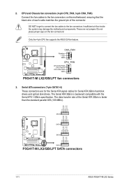
... GND RSATA_RXN2 RSATA_RXP2 GND RSATA_TXN2 RSATA_TXP2 GND GND RSATA_RXN1 RSATA_RXP1 GND RSATA_TXN1 RSATA_TXP1 GND P5G41T-M LX2/GB/LPT SATA2 SATA1 P5G41T-M LX2/GB/LPT SATA connectors 1-11 ASUS P5G41T-M LX2 Series DO NOT forget to connect the fan cables to the fan connectors on the fan connectors! The Serial ATA 3Gb/s is faster than the standard parallel ATA (133 MB/s). P5G41T...
... GND RSATA_RXN2 RSATA_RXP2 GND RSATA_TXN2 RSATA_TXP2 GND GND RSATA_RXN1 RSATA_RXP1 GND RSATA_TXN1 RSATA_TXP1 GND P5G41T-M LX2/GB/LPT SATA2 SATA1 P5G41T-M LX2/GB/LPT SATA connectors 1-11 ASUS P5G41T-M LX2 Series DO NOT forget to connect the fan cables to the fan connectors on the fan connectors! The Serial ATA 3Gb/s is faster than the standard parallel ATA (133 MB/s). P5G41T...
User Manual
Page 21
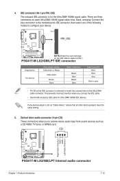
... cable to configure your device. PIN1 PRI_IDE P5G41T-M LX2/GB/LPT NOTE:Orient the red markings on the IDE connector is for Ultra DMA 100/66 IDE devices. IDE connector (40-1 pin PRI_IDE) The onboard IDE connector is removed to receive stereo audio input from sound ...same setting. 5. CD Right Audio Channel GND GND Left Audio Channel P5G41T-M LX2/GB/LPT P5G41T-M LX2/GB/LPT Internal audio connector Chapter 1: Product introduction 1-12 There are three connectors on the Ultra DMA cable connector. This prevents incorrect insertion when you to match the covered hole on each Ultra...
... cable to configure your device. PIN1 PRI_IDE P5G41T-M LX2/GB/LPT NOTE:Orient the red markings on the IDE connector is for Ultra DMA 100/66 IDE devices. IDE connector (40-1 pin PRI_IDE) The onboard IDE connector is removed to receive stereo audio input from sound ...same setting. 5. CD Right Audio Channel GND GND Left Audio Channel P5G41T-M LX2/GB/LPT P5G41T-M LX2/GB/LPT Internal audio connector Chapter 1: Product introduction 1-12 There are three connectors on the Ultra DMA cable connector. This prevents incorrect insertion when you to match the covered hole on each Ultra...
User Manual
Page 22
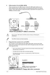
...+5V USB_P8USB_P8+ GND NC USB+5V USB_P6USB_P6+ GND NC P5G41T-M LX2/GB/LPT USB56 PIN 1 USB78 PIN 1 USB+5V USB_P7USB_P7+ GND USB+5V USB_P5USB_P5+ GND P5G41T-M LX2/GB/LPT USB2.0 connectors Never connect a 1394 cable to 480Mbps connection speed. P5G41T-M LX2/GB/LPT Floppy disk drive connector 1-13 ASUS P5G41T-M LX2 Series These USB connectors comply with a covered Pin 5. • The floppy disk drive...
...+5V USB_P8USB_P8+ GND NC USB+5V USB_P6USB_P6+ GND NC P5G41T-M LX2/GB/LPT USB56 PIN 1 USB78 PIN 1 USB+5V USB_P7USB_P7+ GND USB+5V USB_P5USB_P5+ GND P5G41T-M LX2/GB/LPT USB2.0 connectors Never connect a 1394 cable to 480Mbps connection speed. P5G41T-M LX2/GB/LPT Floppy disk drive connector 1-13 ASUS P5G41T-M LX2 Series These USB connectors comply with a covered Pin 5. • The floppy disk drive...
User Manual
Page 23
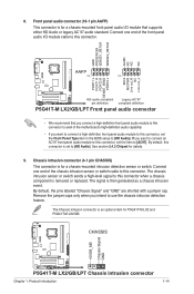
...for a chassis-mounted intrusion detection sensor or switch. The Chassis intrusion connector is for P5G41T-M LX2 and P5G41T-M LX2/GB. CHASSIS +5VSB_MB Chassis Signal GND P5G41T-M LX2/GB/LPT P5G41T-M LX2/GB/LPT Chassis intrusion connector Chapter 1: Product introduction 1-14 Connect one end of the front panel...NC Line out_L PORT1 L PORT1 R PORT2 R SENSE_SEND PORT2 L P5G41T-M LX2/GB/LPT HD-audio-compliant Legacy AC'97 pin definition compliant definition P5G41T-M LX2/GB/LPT Front panel audio connector • We recommend that supports either HD Audio or legacy AC`97 audio...
...for a chassis-mounted intrusion detection sensor or switch. The Chassis intrusion connector is for P5G41T-M LX2 and P5G41T-M LX2/GB. CHASSIS +5VSB_MB Chassis Signal GND P5G41T-M LX2/GB/LPT P5G41T-M LX2/GB/LPT Chassis intrusion connector Chapter 1: Product introduction 1-14 Connect one end of the front panel...NC Line out_L PORT1 L PORT1 R PORT2 R SENSE_SEND PORT2 L P5G41T-M LX2/GB/LPT HD-audio-compliant Legacy AC'97 pin definition compliant definition P5G41T-M LX2/GB/LPT Front panel audio connector • We recommend that supports either HD Audio or legacy AC`97 audio...
User Manual
Page 24
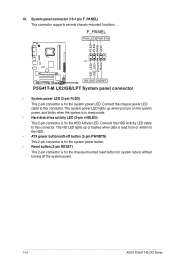
... the system power. 1-15 ASUS P5G41T-M LX2 Series PLED+ PLEDPWR GND IDE_LED+ IDE_LED- F_PANEL PWR LED PWR BTN PIN 1 P5G41T-M LX2/GB/LPT HD LED RESET P5G41T-M LX2/GB/LPT System panel connector • System power LED (2-pin PLED) This 2-pin connector is read from or written to this connector. System panel connector (10-1 pin F_PANEL) This connector supports several chassis-mounted functions...
... the system power. 1-15 ASUS P5G41T-M LX2 Series PLED+ PLEDPWR GND IDE_LED+ IDE_LED- F_PANEL PWR LED PWR BTN PIN 1 P5G41T-M LX2/GB/LPT HD LED RESET P5G41T-M LX2/GB/LPT System panel connector • System power LED (2-pin PLED) This 2-pin connector is read from or written to this connector. System panel connector (10-1 pin F_PANEL) This connector supports several chassis-mounted functions...
User Manual
Page 28
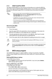
...The removable devices that ASUS CrashFree BIOS support vary with its parameters. For motherboards without the floppy connector, prepare a USB flash disk before using this utility, rename the BIOS file in the removable device into PG41TML2.ROM (P5G41T-M LX2) / PG41TMLG.ROM (P5G41T-M LX2/GB) / PG41TMLP.ROM (P5G41T-M LX2/GB/LPT). • The... device that contains the BIOS file to the USB port or to enter BIOS Setup using the first two options. 2-3 ASUS P5G41T-M LX2 Series Select the Load Setup Defaults item under the Exit menu. Entering BIOS Setup after POST To enter BIOS Setup after ...
...The removable devices that ASUS CrashFree BIOS support vary with its parameters. For motherboards without the floppy connector, prepare a USB flash disk before using this utility, rename the BIOS file in the removable device into PG41TML2.ROM (P5G41T-M LX2) / PG41TMLG.ROM (P5G41T-M LX2/GB) / PG41TMLP.ROM (P5G41T-M LX2/GB/LPT). • The... device that contains the BIOS file to the USB port or to enter BIOS Setup using the first two options. 2-3 ASUS P5G41T-M LX2 Series Select the Load Setup Defaults item under the Exit menu. Entering BIOS Setup after POST To enter BIOS Setup after ...


