
Motherboard DIY Troubleshooting Guide
Page 39
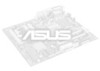
ON 12345 ON 12345 ON 12345 DSW1 CPU 100.00MHz AGP 67.00MHz PCI 33.00MHz 105.00MHz 70.00MHz 35.00MHz 110.00MHz 73.00MHz 37.00MHz ON 12345 ON 12345 ON 12345 CPU 115.00MHz AGP 77.00MHz PCI 38.00MHz 120.00MHz 80.00MHz 40.00MHz 133.00MHz 67.00MHz 33.00MHz P4T533 ® ON 12345 ON 12345 ON 12345 P4T533 CPU External Frequency Selection CPU 136.00MHz AGP 68.00MHz PCI 34.00MHz 140.00MHz 70.00MHz 35.00MHz 145.00MHz 73.00MHz 36.00MHz 23
ON 12345 ON 12345 ON 12345 DSW1 CPU 100.00MHz AGP 67.00MHz PCI 33.00MHz 105.00MHz 70.00MHz 35.00MHz 110.00MHz 73.00MHz 37.00MHz ON 12345 ON 12345 ON 12345 CPU 115.00MHz AGP 77.00MHz PCI 38.00MHz 120.00MHz 80.00MHz 40.00MHz 133.00MHz 67.00MHz 33.00MHz P4T533 ® ON 12345 ON 12345 ON 12345 P4T533 CPU External Frequency Selection CPU 136.00MHz AGP 68.00MHz PCI 34.00MHz 140.00MHz 70.00MHz 35.00MHz 145.00MHz 73.00MHz 36.00MHz 23

Motherboard DIY Troubleshooting Guide
Page 40
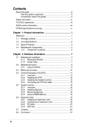
P4T533 ® P4T533 CPU Frequency Multiple Selection DSW (P4 533MHZ) ON ON ON 1234 12.0x ON 1234 13.0x ON 1234 16.0x ON 1234 19.0x 1234 20.0x 1234 21.0x DSW (P4 400MHZ) ON ON ON 1234 16.0x ON 1234 17.0x ON 1234 18.0x ON 1234 21.0x 1234 22.0x 1234 23.0x ON 1234 17.0x ON 1234 22.0x ON 1234 19.0x ON 1234 24.0x ON 1234 18.0x ON 1234 23.0x ON 1234 20.0x 24
P4T533 ® P4T533 CPU Frequency Multiple Selection DSW (P4 533MHZ) ON ON ON 1234 12.0x ON 1234 13.0x ON 1234 16.0x ON 1234 19.0x 1234 20.0x 1234 21.0x DSW (P4 400MHZ) ON ON ON 1234 16.0x ON 1234 17.0x ON 1234 18.0x ON 1234 21.0x 1234 22.0x 1234 23.0x ON 1234 17.0x ON 1234 22.0x ON 1234 19.0x ON 1234 24.0x ON 1234 18.0x ON 1234 23.0x ON 1234 20.0x 24
P4T533 User Manual
Page 4
... iii How this guide is organized iii Conventions used in this guide iii Safety information vi FCC/CDC statements vii ASUS contact information viii P4T533 specifications summary ix Chapter 1: Product introduction 1 Welcome 1 1.1 Package contents 1 1.2 Core Specifications 2 1.3 Special Features... 8 2.2.1 Layout contents 9 2.3 Before you proceed 10 2.4 Central Processing Unit (CPU 11 2.4.1 Overview 11 2.4.2 Installing the CPU 12 2.4.3 Installing the heatsink and fan 13 2.4.4 Connecting the CPU fan cable 15 2.5 System memory 16 2.5.1 Overview 16 2.5.2 Installing Memory 17 2.5.3...
... iii How this guide is organized iii Conventions used in this guide iii Safety information vi FCC/CDC statements vii ASUS contact information viii P4T533 specifications summary ix Chapter 1: Product introduction 1 Welcome 1 1.1 Package contents 1 1.2 Core Specifications 2 1.3 Special Features... 8 2.2.1 Layout contents 9 2.3 Before you proceed 10 2.4 Central Processing Unit (CPU 11 2.4.1 Overview 11 2.4.2 Installing the CPU 12 2.4.3 Installing the heatsink and fan 13 2.4.4 Connecting the CPU fan cable 15 2.5 System memory 16 2.5.1 Overview 16 2.5.2 Installing Memory 17 2.5.3...

P4T533 User Manual
Page 9
...IDE controller Intel® 8256ET ethernet controller (optional) ASUS JumperFree™ mode ASUS POST Reporter™ ASUS EZ Plug™ ASUS EZ Flash ASUS MyLogo2™ ASUS Q-Fan ASUS Multi-language BIOS S/PDIF In/Out Module bundled (optional) Power Loss Restart Adjustable CPU VCORE AGP warning LED Rear panel I/O 1 x Parallel... 2 x 232-pin 32-bit RIMM4200/3200-compliant Rambus DRAMs (RDRAMs) up to 2GB. P4T533 specifications summary CPU Socket 478 for 2 additional USB ports CPU/Power/Chassis fan connectors 20-pin/4-pin ATX power connectors IDE LED/Power LED connectors Chassis intrusion...
...IDE controller Intel® 8256ET ethernet controller (optional) ASUS JumperFree™ mode ASUS POST Reporter™ ASUS EZ Plug™ ASUS EZ Flash ASUS MyLogo2™ ASUS Q-Fan ASUS Multi-language BIOS S/PDIF In/Out Module bundled (optional) Power Loss Restart Adjustable CPU VCORE AGP warning LED Rear panel I/O 1 x Parallel... 2 x 232-pin 32-bit RIMM4200/3200-compliant Rambus DRAMs (RDRAMs) up to 2GB. P4T533 specifications summary CPU Socket 478 for 2 additional USB ports CPU/Power/Chassis fan connectors 20-pin/4-pin ATX power connectors IDE LED/Power LED connectors Chassis intrusion...
P4T533 User Manual
Page 13
...Intel® Pentium® 4 Processor coupled with the Intel 850E chipset to set a new benchmark for an effective desktop platform solution. ~ CPU Thermal Protection ~ Up to 2GB of system memory of RIMM4200/RIMM3200 RDRAM ~ High-resolution graphics via an AGP Pro slot ~ Digital Audio...eight more Before installing the motherboard, check the items in your package: 1.1 Package contents Check your P4T533 package for the following items. ASUS P4T533 motherboard (ATX form factor: 12-in x 9.6-in) ASUS P4T533 support CD 3x 80-conductor ribbon cable for UltraDMA/33/66/100 IDE drives 40-conductor IDE ...
...Intel® Pentium® 4 Processor coupled with the Intel 850E chipset to set a new benchmark for an effective desktop platform solution. ~ CPU Thermal Protection ~ Up to 2GB of system memory of RIMM4200/RIMM3200 RDRAM ~ High-resolution graphics via an AGP Pro slot ~ Digital Audio...eight more Before installing the motherboard, check the items in your package: 1.1 Package contents Check your P4T533 package for the following items. ASUS P4T533 motherboard (ATX form factor: 12-in x 9.6-in) ASUS P4T533 support CD 3x 80-conductor ribbon cable for UltraDMA/33/66/100 IDE drives 40-conductor IDE ...
P4T533 User Manual
Page 18
...23, 24 and 66.) • Adjustable Vcore Voltage (See page 27 and 66.) Temperature, Fan and Voltage Monitoring: ASUS ASIC and the CPU's internal thermal diode monitors temperature to accommodate the S/PDIF (Sony/Philips Digital Interface Output module -- Chassis intrusion detection The ...motherboard supports chassis intrusion monitoring through the ASUS ASIC. Auto fan off The system fans power off mode, depending on the...
...23, 24 and 66.) • Adjustable Vcore Voltage (See page 27 and 66.) Temperature, Fan and Voltage Monitoring: ASUS ASIC and the CPU's internal thermal diode monitors temperature to accommodate the S/PDIF (Sony/Philips Digital Interface Output module -- Chassis intrusion detection The ...motherboard supports chassis intrusion monitoring through the ASUS ASIC. Auto fan off The system fans power off mode, depending on the...

P4T533 User Manual
Page 23
... USB Device Wake-up (+5V / +5VSB) 6) BCS1, BCS2 p. 26 Bass Center Setting (Bass Center / Center Bass) 7) KBPWR p. 26 Keyboard Wake Up (+5V, +5VSB) 8) OVER_VOLT p. 27 CPU Over Voltage Setting (Normal / OverVoltage) 9) SPEECH p. 27 Speaker Selector (Buzzer / Lineout) 10) RAID_SW p. 28 RAID IDE Setting (Enable / Disable) 11) CLRTC p. 29 Clear RTC RAM...) USB20_34 p. 39 USB 2.0 Headers (10-1 pin) 17) CD, AUX, MODEM p. 40 Internal Audio Connectors (Three 4-1 pin) (optional) 18) CHASSIS p. 40 Chassis Open Alarm Lead (4-1 pin) ASUS P4T533 motherboard user guide 9
... USB Device Wake-up (+5V / +5VSB) 6) BCS1, BCS2 p. 26 Bass Center Setting (Bass Center / Center Bass) 7) KBPWR p. 26 Keyboard Wake Up (+5V, +5VSB) 8) OVER_VOLT p. 27 CPU Over Voltage Setting (Normal / OverVoltage) 9) SPEECH p. 27 Speaker Selector (Buzzer / Lineout) 10) RAID_SW p. 28 RAID IDE Setting (Enable / Disable) 11) CLRTC p. 29 Clear RTC RAM...) USB20_34 p. 39 USB 2.0 Headers (10-1 pin) 17) CD, AUX, MODEM p. 40 Internal Audio Connectors (Three 4-1 pin) (optional) 18) CHASSIS p. 40 Chassis Open Alarm Lead (4-1 pin) ASUS P4T533 motherboard user guide 9

P4T533 User Manual
Page 25
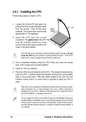
... the socket may bend the pins and severely damage the CPU! This mark indicates the processor Pin 1 that the CPU has a gold triangular mark on one corner. Incorrect installation of 4.2 GB/s and 3.2GB/s. P4T533 ® Gold Arrow P4T533 Socket 478 The Intel Pentium 4 Processor in the illustration ...that should match a specific corner of the CPU socket. Gold Mark Note in the 478-pin package uses the Flip-Chip Pin Grid Array 2 (FC-PGA2) package technology, and includes the Intel® NetBurst™ micro-architecture. ASUS P4T533 motherboard user guide 11 This socket is ...
... the socket may bend the pins and severely damage the CPU! This mark indicates the processor Pin 1 that the CPU has a gold triangular mark on one corner. Incorrect installation of 4.2 GB/s and 3.2GB/s. P4T533 ® Gold Arrow P4T533 Socket 478 The Intel Pentium 4 Processor in the illustration ...that should match a specific corner of the CPU socket. Gold Mark Note in the 478-pin package uses the Flip-Chip Pin Grid Array 2 (FC-PGA2) package technology, and includes the Intel® NetBurst™ micro-architecture. ASUS P4T533 motherboard user guide 11 This socket is ...
P4T533 User Manual
Page 26
... locking brace to scrape the motherboard surface when mounting a clampstyle processor fan, or else damage may occur! Once completely inserted, press the CPU firmly and close the socket lever until it by pulling the lever gently sideways away from the socket. When mounting a heatsink onto your ...Chapter 2: Hardware information Then lift the lever upwards. The heatsink should drop easily into the socket to 100 degrees). 2. Do not force the CPU into place. Install an Intel fan heatsink. 5. The gold arrow of the lever handle. Locate the Socket 478 and open it snaps into ...
... locking brace to scrape the motherboard surface when mounting a clampstyle processor fan, or else damage may occur! Once completely inserted, press the CPU firmly and close the socket lever until it by pulling the lever gently sideways away from the socket. When mounting a heatsink onto your ...Chapter 2: Hardware information Then lift the lever upwards. The heatsink should drop easily into the socket to 100 degrees). 2. Do not force the CPU into place. Install an Intel fan heatsink. 5. The gold arrow of the lever handle. Locate the Socket 478 and open it snaps into ...

P4T533 User Manual
Page 27
2.4.3 Installing the heatsink and fan The Intel® Pentium® 4 478 Processor requires a specially designed heatsink and fan assembly to install the CPU heatsink and fan. 1. Follow these steps to ensure optimum thermal condition and performance. ASUS P4T533 motherboard user guide 13 The retention module base is already installed on the retention module base...
2.4.3 Installing the heatsink and fan The Intel® Pentium® 4 478 Processor requires a specially designed heatsink and fan assembly to install the CPU heatsink and fan. 1. Follow these steps to ensure optimum thermal condition and performance. ASUS P4T533 motherboard user guide 13 The retention module base is already installed on the retention module base...

P4T533 User Manual
Page 29
When secure, the retention locks should point to opposite directions. 2.4.4 Connecting the CPU fan cable When the fan, heatsink, and the retention mechanism are in place, connect the CPU fan cable to the connector on the retention mechanism to secure the heatsink and fan to the module base. ASUS P4T533 motherboard user guide 15 3. Push down the locks on the motherboard labeled CPUFAN1. CPU Fan Connector (CPUFAN1) Don't forget to plug this connector. Hardware monitoring errors may occur if you fail to connect the CPU fan connector!
When secure, the retention locks should point to opposite directions. 2.4.4 Connecting the CPU fan cable When the fan, heatsink, and the retention mechanism are in place, connect the CPU fan cable to the connector on the retention mechanism to secure the heatsink and fan to the module base. ASUS P4T533 motherboard user guide 15 3. Push down the locks on the motherboard labeled CPUFAN1. CPU Fan Connector (CPUFAN1) Don't forget to plug this connector. Hardware monitoring errors may occur if you fail to connect the CPU fan connector!
P4T533 User Manual
Page 37
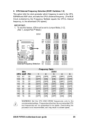
...77.00MHz PCI 38.00MHz 120.00MHz 80.00MHz 40.00MHz 133.00MHz 67.00MHz 33.00MHz P4T533 ® ON 12345 ON 12345 ON 12345 P4T533 CPU External Frequency Selection CPU 136.00MHz AGP 68.00MHz PCI 34.00MHz 140.00MHz 70.00MHz 35.00MHz 145.00MHz ... BUS Clock multiplied by the Frequency Multiple equals the CPU's Internal frequency, or, the advertised CPU speed.) IMPORTANT: 1. CPU External Frequency Selection (DSW1 Switches 1-5) This option tells the clock generator which frequency to send to the recommended settings. ASUS P4T533 motherboard user guide 23 Overclocking the processor is not ...
...77.00MHz PCI 38.00MHz 120.00MHz 80.00MHz 40.00MHz 133.00MHz 67.00MHz 33.00MHz P4T533 ® ON 12345 ON 12345 ON 12345 P4T533 CPU External Frequency Selection CPU 136.00MHz AGP 68.00MHz PCI 34.00MHz 140.00MHz 70.00MHz 35.00MHz 145.00MHz ... BUS Clock multiplied by the Frequency Multiple equals the CPU's Internal frequency, or, the advertised CPU speed.) IMPORTANT: 1. CPU External Frequency Selection (DSW1 Switches 1-5) This option tells the clock generator which frequency to send to the recommended settings. ASUS P4T533 motherboard user guide 23 Overclocking the processor is not ...

P4T533 User Manual
Page 38
... your processor and the bus frequency (133/100MHz). IMPORTANT: 1. 3. Set the DSW switches according to Jumper Mode, [1-2]. (See 1, JumperFree™ Mode.) P4T533 P4T533 CPU Frequency Multiple Selection DSW ON 1234 16.0x ON 1234 21.0x ON 1234 17.0x ON 1234 22.0x ON 1234 18.0x ON...] [OFF] [OFF] [ON] [OFF] [ON] [OFF] [OFF] [OFF] [OFF] [OFF] 4 [ON] [OFF] [OFF] [OFF] [OFF] [OFF] [OFF] [OFF] [OFF] 24 Chapter 2: Hardware information CPU Frequency Multiple Setting (DSW Switches 1-4) Set DSW switches (1-4) to use this feature, JEN must be set to the internal speed of bus speeds with...
... your processor and the bus frequency (133/100MHz). IMPORTANT: 1. 3. Set the DSW switches according to Jumper Mode, [1-2]. (See 1, JumperFree™ Mode.) P4T533 P4T533 CPU Frequency Multiple Selection DSW ON 1234 16.0x ON 1234 21.0x ON 1234 17.0x ON 1234 22.0x ON 1234 18.0x ON...] [OFF] [OFF] [ON] [OFF] [ON] [OFF] [OFF] [OFF] [OFF] [OFF] 4 [ON] [OFF] [OFF] [OFF] [OFF] [OFF] [OFF] [OFF] [OFF] 24 Chapter 2: Hardware information CPU Frequency Multiple Setting (DSW Switches 1-4) Set DSW switches (1-4) to use this feature, JEN must be set to the internal speed of bus speeds with...

P4T533 User Manual
Page 41
... in the chassis). Set to pins [1-2] to the CPU. The default setting, [1-2], permits extra voltage for the ASUS POST Reporter function. OVER_VOLT 12 23 Normal (Default) Over Voltage P4T533 ® P4T533 OVER_VOLT Setting 9. P4T533 ® P4T533 Speaker Selector SPEECH 12 23 BUZZER LINEOUT (Default) ASUS P4T533 motherboard user guide 27 CPU Over Voltage Setting (3 pin OVER_VOLT) This jumper controls...
... in the chassis). Set to pins [1-2] to the CPU. The default setting, [1-2], permits extra voltage for the ASUS POST Reporter function. OVER_VOLT 12 23 Normal (Default) Over Voltage P4T533 ® P4T533 OVER_VOLT Setting 9. P4T533 ® P4T533 Speaker Selector SPEECH 12 23 BUZZER LINEOUT (Default) ASUS P4T533 motherboard user guide 27 CPU Over Voltage Setting (3 pin OVER_VOLT) This jumper controls...
P4T533 User Manual
Page 51
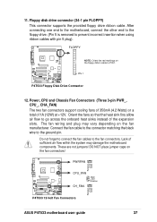
...caps on the fan manufacturer. PWRFAN Rotation +12V GND CPU_FAN GND +12V Rotation P4T533 ® CH_FAN Rotation +12V GND P4T533 12-Volt Fan Connectors ASUS P4T533 motherboard user guide 37 P4T533 ® PIN 1 P4T533 Floppy Disk Drive Connector 12. FLOPPY NOTE: Orient the red markings on the ...5 is removed to PIN 1. Floppy disk drive connector (34-1 pin FLOPPY) This connector supports the provided floppy drive ribbon cable. Power, CPU and Chassis Fan Connectors (Three 3-pin PWR_, CPU_, CHA_FAN) The two fan connectors support cooling fans of 350mA (4.2 Watts) or a ...
...caps on the fan manufacturer. PWRFAN Rotation +12V GND CPU_FAN GND +12V Rotation P4T533 ® CH_FAN Rotation +12V GND P4T533 12-Volt Fan Connectors ASUS P4T533 motherboard user guide 37 P4T533 ® PIN 1 P4T533 Floppy Disk Drive Connector 12. FLOPPY NOTE: Orient the red markings on the ...5 is removed to PIN 1. Floppy disk drive connector (34-1 pin FLOPPY) This connector supports the provided floppy drive ribbon cable. Power, CPU and Chassis Fan Connectors (Three 3-pin PWR_, CPU_, CHA_FAN) The two fan connectors support cooling fans of 350mA (4.2 Watts) or a ...
P4T533 User Manual
Page 52
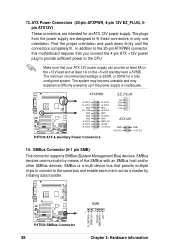
13. In addition to the CPU. Make sure that you connect the 4-pin ATX +12V power plug to provide sufficient power to the 20-pin ATXPWR connector, this motherboard requires that .... The system may become unstable and may experience difficulty powering up if the power supply is 230W, or 300W for an ATX 12V power supply. P4T533 ® P4T533 SMBus Connector SMB 1 FLOATING SMBCLK Ground SMBDATA +3V 38 Chapter 2: Hardware information ATX Power Connectors (20-pin ATXPWR, 4-pin 12V EZ_PLUG, 4pin ATX12V) These...
13. In addition to the CPU. Make sure that you connect the 4-pin ATX +12V power plug to provide sufficient power to the 20-pin ATXPWR connector, this motherboard requires that .... The system may become unstable and may experience difficulty powering up if the power supply is 230W, or 300W for an ATX 12V power supply. P4T533 ® P4T533 SMBus Connector SMB 1 FLOATING SMBCLK Ground SMBDATA +3V 38 Chapter 2: Hardware information ATX Power Connectors (20-pin ATXPWR, 4-pin 12V EZ_PLUG, 4pin ATX12V) These...
P4T533 User Manual
Page 63
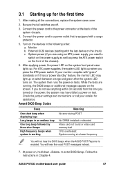
... frequency beeps when system is working Meaning No error during POST No DRAM installed or detected Video card not found or video card memory bad CPU overheated; Connect the power cord to switch on the power supply as well as press the ATX power switch on the chain) c. 3.1 Starting up... 1. Connect the power cord to enter BIOS Setup. While the tests are off. 3. System running , the BIOS beeps or additional messages appear on test. ASUS P4T533 motherboard user guide 47 If you do not see anything within 30 seconds from the time you press the ATX power switch. At power on...
... frequency beeps when system is working Meaning No error during POST No DRAM installed or detected Video card not found or video card memory bad CPU overheated; Connect the power cord to switch on the power supply as well as press the ATX power switch on the chain) c. 3.1 Starting up... 1. Connect the power cord to enter BIOS Setup. While the tests are off. 3. System running , the BIOS beeps or additional messages appear on test. ASUS P4T533 motherboard user guide 47 If you do not see anything within 30 seconds from the time you press the ATX power switch. At power on...
P4T533 User Manual
Page 64
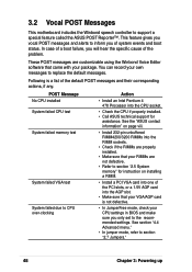
... "4.4 Advanced menu." • In jumper mode, refer to support a special feature called the ASUS POST Reporter™. You can record your package. Following is not defective. • In JumperFree mode, check your CPU settings in BIOS and make sure you of the PCI slots, or a 1.5V AGP card into... the CPU socket. • Check the CPU if properly installed. • Call ASUS technical support for instruction on page viii. • Install 232-pin unbuffered RIMM4200/3200 RIMMs into the RIMM sockets. • Check if...
... "4.4 Advanced menu." • In jumper mode, refer to support a special feature called the ASUS POST Reporter™. You can record your package. Following is not defective. • In JumperFree mode, check your CPU settings in BIOS and make sure you of the PCI slots, or a 1.5V AGP card into... the CPU socket. • Check the CPU if properly installed. • Call ASUS technical support for instruction on page viii. • Install 232-pin unbuffered RIMM4200/3200 RIMMs into the RIMM sockets. • Check if...
P4T533 User Manual
Page 65
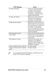
... Reporter in the BIOS setup. See the "ASUS contact information" on the motherboard. • See section "2.8 Connectors." No floppy disk detected • Make sure you have connected an IDE hard disk drive to the system. CPU voltage out of range • Check your keyboard if ...8226; Make sure you have connected a floppy disk to the optional onboard IDE/ RAID controller connector(s), then ignore this message. ASUS P4T533 motherboard user guide 49 See section "4.4.2 I/O Device Configuration". CPU temperature too high • Check CPU fan if working properly.
... Reporter in the BIOS setup. See the "ASUS contact information" on the motherboard. • See section "2.8 Connectors." No floppy disk detected • Make sure you have connected an IDE hard disk drive to the system. CPU voltage out of range • Check your keyboard if ...8226; Make sure you have connected a floppy disk to the optional onboard IDE/ RAID controller connector(s), then ignore this message. ASUS P4T533 motherboard user guide 49 See section "4.4.2 I/O Device Configuration". CPU temperature too high • Check CPU fan if working properly.
P4T533 User Manual
Page 84
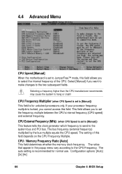
...send to set to [Manual]) This field is recommended for unlocked processors only. This field allows you want to make changes to the CPU Frequency. Select [Manual] if you to the system bus and PCI bus. The ratios that appear in the popup menu vary according ...to the two subsequent fields. CPU Frequency Multiplier (when CPU Speed is set the frequency multiple between the CPU's internal frequency (CPU speed) and external frequency. CPU / Memory Frequency Ratio [Auto] This field determines whether the memory clock frequency. The ...
...send to set to [Manual]) This field is recommended for unlocked processors only. This field allows you want to make changes to the CPU Frequency. Select [Manual] if you to the system bus and PCI bus. The ratios that appear in the popup menu vary according ...to the two subsequent fields. CPU Frequency Multiplier (when CPU Speed is set the frequency multiple between the CPU's internal frequency (CPU speed) and external frequency. CPU / Memory Frequency Ratio [Auto] This field determines whether the memory clock frequency. The ...


