User Manual
Page 1
® P4T-F Intel® 850 ATX Motherboard USER'S MANUAL
® P4T-F Intel® 850 ATX Motherboard USER'S MANUAL
User Manual
Page 4
HARDWARE SETUP 14 3.1 P4T-F Motherboard Layout 14 3.2 Layout Contents 15 3.3 Hardware Setup Procedure 16 3.4 Motherboard Settings 17 3.5 System Memory 23 3.5.1 CPU Installation 25 3.5 Central Processing Unit (CPU 25 3.5.2 CPU Heatsink Retention Module Installation 26 3.6 Expansion Cards ... 4.3.2 Keyboard Features 56 4.4 Advanced Menu 58 4.4.1 Chip Configuration 61 4.4.2 I/O Device Configuration 63 4.4.3 PCI Configuration 65 4.4.4 Shadow Configuration 67 4.5 Power Menu 68 4 ASUS P4T-F User's Manual FEATURES 8 2.1 The ASUS P4T-F 8 2.2 P4T-F Motherboard Components 12 3.
HARDWARE SETUP 14 3.1 P4T-F Motherboard Layout 14 3.2 Layout Contents 15 3.3 Hardware Setup Procedure 16 3.4 Motherboard Settings 17 3.5 System Memory 23 3.5.1 CPU Installation 25 3.5 Central Processing Unit (CPU 25 3.5.2 CPU Heatsink Retention Module Installation 26 3.6 Expansion Cards ... 4.3.2 Keyboard Features 56 4.4 Advanced Menu 58 4.4.1 Chip Configuration 61 4.4.2 I/O Device Configuration 63 4.4.3 PCI Configuration 65 4.4.4 Shadow Configuration 67 4.5 Power Menu 68 4 ASUS P4T-F User's Manual FEATURES 8 2.1 The ASUS P4T-F 8 2.2 P4T-F Motherboard Components 12 3.
User Manual
Page 5
SOFTWARE REFERENCE 80 6.1 ASUS Live Update 80 6.2 ASUS PC Probe 81 6.3 CyberLink PowerPlayer SE 86 6.4 CyberLink VideoLive Mail 87 7. APPENDIX 89 7.1 Glossary 89 INDEX 95 ASUS P4T-F User's Manual 5 CONTENTS 4.5.1 Power Up Control 70 4.5.2 Hardware Monitor 71 4.6 Boot Menu 72 4.7 Exit Menu 74 5. SOFTWARE SETUP 77 5.1 Install Operating System 77 5.2 Start Windows 77 5.3 P4T-F Motherboard Support CD 78 6.
SOFTWARE REFERENCE 80 6.1 ASUS Live Update 80 6.2 ASUS PC Probe 81 6.3 CyberLink PowerPlayer SE 86 6.4 CyberLink VideoLive Mail 87 7. APPENDIX 89 7.1 Glossary 89 INDEX 95 ASUS P4T-F User's Manual 5 CONTENTS 4.5.1 Power Up Control 70 4.5.2 Hardware Monitor 71 4.6 Boot Menu 72 4.7 Exit Menu 74 5. SOFTWARE SETUP 77 5.1 Install Operating System 77 5.2 Start Windows 77 5.3 P4T-F Motherboard Support CD 78 6.
User Manual
Page 7
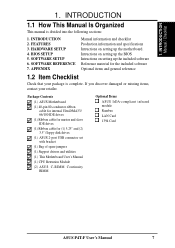
... Production information and specifications Intructions on setting up the motherboard. If you discover damaged or missing items, contact your package is divided into the following sections: 1. Package Contents (1) ASUS Motherboard (1) 40-pin 80-conductor ribbon cable for internal ... Bag of spare jumpers (1) Support drivers and utilities (1) This Motherboard User's Manual (1) CPU Retention Module (2) ASUS C-RIMM Continuity RIMM Optional Items ASUS IrDA-compliant infrared module Rambus LAN Card 1394 Card ASUS P4T-F User's Manual 7 INTRODUCTION 1.1 How This Manual Is Organized This...
... Production information and specifications Intructions on setting up the motherboard. If you discover damaged or missing items, contact your package is divided into the following sections: 1. Package Contents (1) ASUS Motherboard (1) 40-pin 80-conductor ribbon cable for internal ... Bag of spare jumpers (1) Support drivers and utilities (1) This Motherboard User's Manual (1) CPU Retention Module (2) ASUS C-RIMM Continuity RIMM Optional Items ASUS IrDA-compliant infrared module Rambus LAN Card 1394 Card ASUS P4T-F User's Manual 7 INTRODUCTION 1.1 How This Manual Is Organized This...

User Manual
Page 8
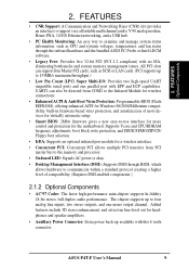
... the PCI bus. • AGP Pro Slot: Comes with an Accelerated Graphics Port Pro slot that support four IDE devices on two channels. FEATURES 2.1 The ASUS P4T-F The ASUS P4T-F motherboard is required. • Intel® Accelerated Hub Architecture: Features a dedicated high speed hub link between the ICH2 and MCH with two connectors that supports...
... the PCI bus. • AGP Pro Slot: Comes with an Accelerated Graphics Port Pro slot that support four IDE devices on two channels. FEATURES 2.1 The ASUS P4T-F The ASUS P4T-F motherboard is required. • Intel® Accelerated Hub Architecture: Features a dedicated high speed hub link between the ICH2 and MCH with two connectors that supports...
User Manual
Page 9
...Auxillary Power Connector: Extra power back-up to four analog line inputs, two stereo outputs, and one parallel port with EPP and ECP capabilities. ASUS P4T-F User's Manual 9 UART2 can support Bus Master PCI cards, such as CPU and systerm voltages, temperatures, and fan status through BIOS, which.... • Onboard LED: Signals AC power is okay. • Desktop Management Interface (DMI): Supports DMI through the onboard hardware and the bundled ASUS PC Probe or Intel LDCM software. • Legacy Free: Provides five 32-bit PCI (PCI 2.2 compliant) with this 6 tooth connector. Supports ...
...Auxillary Power Connector: Extra power back-up to four analog line inputs, two stereo outputs, and one parallel port with EPP and ECP capabilities. ASUS P4T-F User's Manual 9 UART2 can support Bus Master PCI cards, such as CPU and systerm voltages, temperatures, and fan status through BIOS, which.... • Onboard LED: Signals AC power is okay. • Desktop Management Interface (DMI): Supports DMI through the onboard hardware and the bundled ASUS PC Probe or Intel LDCM software. • Legacy Free: Provides five 32-bit PCI (PCI 2.2 compliant) with this 6 tooth connector. Supports ...
User Manual
Page 10
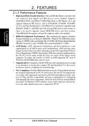
... is also implemented on the following high-level goals: support for Plug and Play compatibility and power management for configuring and managing all ASUS smart series motherboards. UltraDMA/100 is backward compatible with DMA/66, DMA/33, and DMA and with a peak bandwidth of ACPI, an ACPI-supported...UltraDMA/100/66, UltraDMA/33 (IDE DMA Mode 2), PIO Modes 3 & 4, and supports Enhanced IDE devices, such as required by PC 99. 10 ASUS P4T-F User's Manual Color-coded connectors and descriptive icons make identification easy as DVD-ROM, CD-ROM, CD-R/RW, LS-120, and Tape Backup drives. ...
... is also implemented on the following high-level goals: support for Plug and Play compatibility and power management for configuring and managing all ASUS smart series motherboards. UltraDMA/100 is backward compatible with DMA/66, DMA/33, and DMA and with a peak bandwidth of ACPI, an ACPI-supported...UltraDMA/100/66, UltraDMA/33 (IDE DMA Mode 2), PIO Modes 3 & 4, and supports Enhanced IDE devices, such as required by PC 99. 10 ASUS P4T-F User's Manual Color-coded connectors and descriptive icons make identification easy as DVD-ROM, CD-ROM, CD-R/RW, LS-120, and Tape Backup drives. ...
User Manual
Page 11
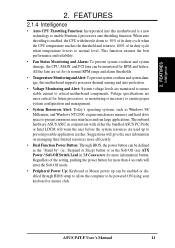
...8226; Temperature Monitoring andAlert: To prevent system overheat and system damage, this motherboard is enabled, the CPU with either the bundled ASUS PC Probe or Intel LDCM will give the user information on managing their ... stable current to normal level. FEATURES 2.1.4 Intelligence • Auto CPU Throttling Function: Incorporated into this motherboard supports processor thermal sensing and auto-protection. • Voltage Monitoring and Alert: System voltage levels are more...technology to present enormous user interfaces and run large applications. ASUS P4T-F User's Manual 11
...8226; Temperature Monitoring andAlert: To prevent system overheat and system damage, this motherboard is enabled, the CPU with either the bundled ASUS PC Probe or Intel LDCM will give the user information on managing their ... stable current to normal level. FEATURES 2.1.4 Intelligence • Auto CPU Throttling Function: Incorporated into this motherboard supports processor thermal sensing and auto-protection. • Voltage Monitoring and Alert: System voltage levels are more...technology to present enormous user interfaces and run large applications. ASUS P4T-F User's Manual 11
User Manual
Page 12
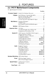
FEATURES 2.2 P4T-F Motherboard Components See opposite page for Pentium 4 Processors 2 Chipsets Intel 850 Memory Controller Hub (MCH 4 Intel I/O Controller Hub 2 (ICH2 11 2Mbit Firmware Hub (FWH 13 Low ... Microphone 2 Connector 21 1 Game/MIDI Connector Top) 22 1 Line Out Connector Bottom) 22 1 Line In Connector Bottom) 22 1 Line Microphone Connector Bottom) 22 Hardware Monitoring ASUS onboard chipset 10 Power ATX Power Supply Connector 1 ATX 12V Power Supply Connector 3 Special Feature Auxillary Power Connector 6 Onboard LED 14 Form Factor ATX 12...
FEATURES 2.2 P4T-F Motherboard Components See opposite page for Pentium 4 Processors 2 Chipsets Intel 850 Memory Controller Hub (MCH 4 Intel I/O Controller Hub 2 (ICH2 11 2Mbit Firmware Hub (FWH 13 Low ... Microphone 2 Connector 21 1 Game/MIDI Connector Top) 22 1 Line Out Connector Bottom) 22 1 Line In Connector Bottom) 22 1 Line Microphone Connector Bottom) 22 Hardware Monitoring ASUS onboard chipset 10 Power ATX Power Supply Connector 1 ATX 12V Power Supply Connector 3 Special Feature Auxillary Power Connector 6 Onboard LED 14 Form Factor ATX 12...
User Manual
Page 14
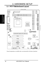
HARDWARE SETUP 3.1 P4T-F Motherboard Layout PS/2KBMS T: Mouse B: Keyboard USB T: Port1 B: Port2 COM1 24.4cm (9.60in) ATX Power Connector USBPWR RIMMB2 (16/18 bit, 184-pin module) RIMMB1 (16/... (ICH2) CLRTC HDDLED Super I/O PCI3 P4T-F PCI4 PCI5 LED CNR_SLOT IR ADN 2Mbit Firmware Hub J3J3+ USB2 ASUS ASIC with Hardware Monitor PCI_FAN JEN DIP Switches OC3 CHASSIS PANEL Grayed components are available only on certain models at the time of purchase. 14 ASUS P4T-F User's Manual 3. H/W SETUP Motherboard Layout 30.5cm (12.0in) AUX...
HARDWARE SETUP 3.1 P4T-F Motherboard Layout PS/2KBMS T: Mouse B: Keyboard USB T: Port1 B: Port2 COM1 24.4cm (9.60in) ATX Power Connector USBPWR RIMMB2 (16/18 bit, 184-pin module) RIMMB1 (16/... (ICH2) CLRTC HDDLED Super I/O PCI3 P4T-F PCI4 PCI5 LED CNR_SLOT IR ADN 2Mbit Firmware Hub J3J3+ USB2 ASUS ASIC with Hardware Monitor PCI_FAN JEN DIP Switches OC3 CHASSIS PANEL Grayed components are available only on certain models at the time of purchase. 14 ASUS P4T-F User's Manual 3. H/W SETUP Motherboard Layout 30.5cm (12.0in) AUX...
User Manual
Page 15
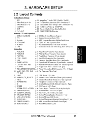
... Management Interrupt Switch Lead (2 pin) 23) PWRSW (PANEL) p.41 ATX Power / Soft-Off Switch Lead (2 pin) 24) RESET (PANEL) p.41 Reset Switch Lead (2 pin) ASUS P4T-F User's Manual 15 Freq. H/W SETUP Layout Contents 3. HARDWARE SETUP 3.2 Layout Contents Motherboard Settings 1) JEN p. 18 JumperFree™ Mode (JEN) (Disable / Enable) 2) SW1 (Switches 6-10) p. 19 CPU Ext. 3.
... Management Interrupt Switch Lead (2 pin) 23) PWRSW (PANEL) p.41 ATX Power / Soft-Off Switch Lead (2 pin) 24) RESET (PANEL) p.41 Reset Switch Lead (2 pin) ASUS P4T-F User's Manual 15 Freq. H/W SETUP Layout Contents 3. HARDWARE SETUP 3.2 Layout Contents Motherboard Settings 1) JEN p. 18 JumperFree™ Mode (JEN) (Disable / Enable) 2) SW1 (Switches 6-10) p. 19 CPU Ext. 3.
User Manual
Page 16
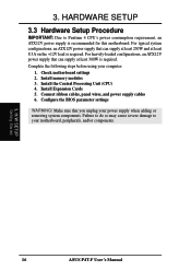
...cause severe damage to Pentium 4 CPU's power consumption requirement, an ATX12V power supply is required. Complete the following steps before using your motherboard, peripherals, and/or components. 3. Make sure that can supply at least 8.5A on the +12V lead is required. 3. Install... memory modules 3. H/W SETUP Getting Started 16 ASUS P4T-F User's Manual HARDWARE SETUP 3.3 Hardware Setup Procedure IMPORTANT: Due to your computer: 1. Install the Central Processing Unit (CPU) 4. For heavily...
...cause severe damage to Pentium 4 CPU's power consumption requirement, an ATX12V power supply is required. Complete the following steps before using your motherboard, peripherals, and/or components. 3. Make sure that can supply at least 8.5A on the +12V lead is required. 3. Install... memory modules 3. H/W SETUP Getting Started 16 ASUS P4T-F User's Manual HARDWARE SETUP 3.3 Hardware Setup Procedure IMPORTANT: Due to your computer: 1. Install the Central Processing Unit (CPU) 4. For heavily...

User Manual
Page 17
... components by the edges and try not to a metal object, such as the power supply case. 3. 3. To protect them against damage from the system. 5. H/W SETUP Motherboard Settings ASUS P4T-F User's Manual 17 WARNING! Unplug your computer when working on the bag that the ATX power supply is switched off before handling computer components...
... components by the edges and try not to a metal object, such as the power supply case. 3. 3. To protect them against damage from the system. 5. H/W SETUP Motherboard Settings ASUS P4T-F User's Manual 17 WARNING! Unplug your computer when working on the bag that the ATX power supply is switched off before handling computer components...
User Manual
Page 18
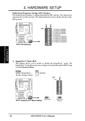
...Default) 18 ASUS P4T-F User's Manual Frequency Multiple 4. Frequency Selection 10. Frequency Selection 7. Frequency Selection 9. Frequency Selection 3. Frequency Selection 8. The JumperFree™ mode allows processor settings to enable or disable the JumperFree™ mode. H/W SETUP Motherboard Settings 1)... JumperFree™ Mode (JEN) This jumper allows you to be made through the DIP switches. P4T-F P4T-F DIP Switches ON 1 2 3 4 5 6 7 8 9 10 ON ...
...Default) 18 ASUS P4T-F User's Manual Frequency Multiple 4. Frequency Selection 10. Frequency Selection 7. Frequency Selection 9. Frequency Selection 3. Frequency Selection 8. The JumperFree™ mode allows processor settings to enable or disable the JumperFree™ mode. H/W SETUP Motherboard Settings 1)... JumperFree™ Mode (JEN) This jumper allows you to be made through the DIP switches. P4T-F P4T-F DIP Switches ON 1 2 3 4 5 6 7 8 9 10 ON ...
User Manual
Page 19
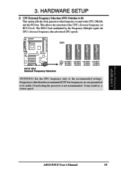
... not guaranteed to the CPU, DRAM, and the PCI bus. This allows the selection of the CPU's External frequency (or BUS Clock). ASUS P4T-F User's Manual 19 H/W SETUP Motherboard Settings 3. SW1 P4T-F P4T-F CPU External Frequency Selection CPU 100.0MHz 103.0MHz 105.0MHz 110.0MHz AGP 66.0MHz 68.0MHz 70.0MHz 73.0MHz...
... not guaranteed to the CPU, DRAM, and the PCI bus. This allows the selection of the CPU's External frequency (or BUS Clock). ASUS P4T-F User's Manual 19 H/W SETUP Motherboard Settings 3. SW1 P4T-F P4T-F CPU External Frequency Selection CPU 100.0MHz 103.0MHz 105.0MHz 110.0MHz AGP 66.0MHz 68.0MHz 70.0MHz 73.0MHz...
User Manual
Page 20
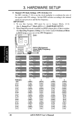
IMPORTANT: 1. When JumperFree mode is enabled, use this feature, JEN must be set to User Define under 4.4 Advanced Menu in 3, HARDWARE SETUP.) 2. H/W SETUP Motherboard Settings P4T-F CPU External Clock (BUS) Frequency P4T-F Selection ON ON ON ON 1 2 3 4 5 6 7 8 9 10 8.0x ON 1 2 3 4 5 6 7 8 9 10 13.0x ON 1 2 3 4 5 6 7 8 9 10 17.0x ON... [OFF] [OFF] [OFF] [OFF] [OFF] [OFF] [ON] [ON] [ON] [ON] [ON] [ON] [ON] [ON] 20 ASUS P4T-F User's Manual To use BIOS setup in place of these switches. (Set Operating Frequency Setting to Jumper Mode, [1-2]. (See 1, JumperFree™ Mode (JEN...
IMPORTANT: 1. When JumperFree mode is enabled, use this feature, JEN must be set to User Define under 4.4 Advanced Menu in 3, HARDWARE SETUP.) 2. H/W SETUP Motherboard Settings P4T-F CPU External Clock (BUS) Frequency P4T-F Selection ON ON ON ON 1 2 3 4 5 6 7 8 9 10 8.0x ON 1 2 3 4 5 6 7 8 9 10 13.0x ON 1 2 3 4 5 6 7 8 9 10 17.0x ON... [OFF] [OFF] [OFF] [OFF] [OFF] [OFF] [ON] [ON] [ON] [ON] [ON] [ON] [ON] [ON] 20 ASUS P4T-F User's Manual To use BIOS setup in place of these switches. (Set Operating Frequency Setting to Jumper Mode, [1-2]. (See 1, JumperFree™ Mode (JEN...
User Manual
Page 21
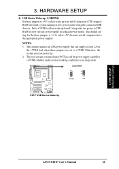
... to select +5V (because not all computers have the appropriate power supply). system running in sleep mode. power supply in slow refresh; USBPWR 2 1 +5VSB 3 2 +5V P4T-F P4T-F USB Device Wake Up 3. H/W SETUP Motherboard Settings ASUS P4T-F User's Manual 21 RAM refreshed; RAM in reduced power mode).
... to select +5V (because not all computers have the appropriate power supply). system running in sleep mode. power supply in slow refresh; USBPWR 2 1 +5VSB 3 2 +5V P4T-F P4T-F USB Device Wake Up 3. H/W SETUP Motherboard Settings ASUS P4T-F User's Manual 21 RAM refreshed; RAM in reduced power mode).
User Manual
Page 22
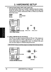
H/W SETUP Motherboard Settings P4T-F P4T-F AUDIO Setting ADN 2 1 ENABLE AUDIO 3 2 DISABLE AUDIO 6) USB2 / CNRUSB Selection (J3-J3-/OC3) The CNR slot can support an optional USB hub CNR card. P4T-F A7V266 CNR/USB Selection 12 J3J3+ 2 1 OC3 USB2 23 J3J3+ 3 2 OC3 CNRUSB 22 ASUS P4T-F User's Manual IMPORTANT! Always set all three jumpers accordingly when selecting a device...
H/W SETUP Motherboard Settings P4T-F P4T-F AUDIO Setting ADN 2 1 ENABLE AUDIO 3 2 DISABLE AUDIO 6) USB2 / CNRUSB Selection (J3-J3-/OC3) The CNR slot can support an optional USB hub CNR card. P4T-F A7V266 CNR/USB Selection 12 J3J3+ 2 1 OC3 USB2 23 J3J3+ 3 2 OC3 CNRUSB 22 ASUS P4T-F User's Manual IMPORTANT! Always set all three jumpers accordingly when selecting a device...

User Manual
Page 23
When C-RIMMs are required, it is recommended that they be used in this motherboard. C-RIMM 128MB RDRAM C-RIMM 128MB RDRAM RIMMB2 RIMMB1 RIMMA2 RIMMA1 NOTE: When using only two memory modules, it is recommended that are... Direct RDRAM technologies. b. 128MB RDRAM RIMMB2 C-RIMM RIMMB1 128MB RDRAM C-RIMM RIMMA2 RIMMA1 c. 128MB RDRAM RIMMB2 128MB RDRAM RIMMB1 128MB RDRAM 128MB RDRAM RIMMA2 RIMMA1 ASUS P4T-F User's Manual 23 Location Memory Module Subtotal RIMMA1 (Rows 0&1) RDRAM x 1 C-RIMM (use when socket will not be populated) RIMMA2 (Rows 2&3) RDRAM x 1...
When C-RIMMs are required, it is recommended that they be used in this motherboard. C-RIMM 128MB RDRAM C-RIMM 128MB RDRAM RIMMB2 RIMMB1 RIMMA2 RIMMA1 NOTE: When using only two memory modules, it is recommended that are... Direct RDRAM technologies. b. 128MB RDRAM RIMMB2 C-RIMM RIMMB1 128MB RDRAM C-RIMM RIMMA2 RIMMA1 c. 128MB RDRAM RIMMB2 128MB RDRAM RIMMB1 128MB RDRAM 128MB RDRAM RIMMA2 RIMMA1 ASUS P4T-F User's Manual 23 Location Memory Module Subtotal RIMMA1 (Rows 0&1) RDRAM x 1 C-RIMM (use when socket will not be populated) RIMMA2 (Rows 2&3) RDRAM x 1...
User Manual
Page 78
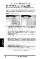
... Controller - S/W SETUP Support CD • INF Update Utility for Intel 850 Chipset: Installs INF files in PDF format. SOFTWARE SETUP 5.3 P4T-F Motherboard Support CD NOTE: The support CD contents are subject to view information about your CD-ROM drive and the support CD installation menu should appear...change at any time without notice. To begin using your support CD disc, just insert it into your motherboard, such as product name, BIOS version, and CPU. (TO SEE THE FOLLOWING ITEMS, CLICK RIGHT ARROW ON THE LOWERRIGHT CORNER OF THE MAIN MENU) 78 ASUS P4T-F User's Manual 5.
... Controller - S/W SETUP Support CD • INF Update Utility for Intel 850 Chipset: Installs INF files in PDF format. SOFTWARE SETUP 5.3 P4T-F Motherboard Support CD NOTE: The support CD contents are subject to view information about your CD-ROM drive and the support CD installation menu should appear...change at any time without notice. To begin using your support CD disc, just insert it into your motherboard, such as product name, BIOS version, and CPU. (TO SEE THE FOLLOWING ITEMS, CLICK RIGHT ARROW ON THE LOWERRIGHT CORNER OF THE MAIN MENU) 78 ASUS P4T-F User's Manual 5.


