User Manual
Page 4
FEATURES 8 2.1 The ASUS P4T-F 8 2.2 P4T-F Motherboard Components 12 3. CONTENTS 1. HARDWARE SETUP 14 3.1 P4T-F Motherboard Layout 14 3.2 Layout Contents 15 3.3 Hardware Setup Procedure 16 3.4 Motherboard Settings 17 3.5 System Memory 23 3.5.1 CPU Installation 25 3.5 Central Processing Unit (CPU 25 3.5.2 CPU Heatsink Retention Module Installation... Configuration 61 4.4.2 I/O Device Configuration 63 4.4.3 PCI Configuration 65 4.4.4 Shadow Configuration 67 4.5 Power Menu 68 4 ASUS P4T-F User's Manual INTRODUCTION 7 1.1 How This Manual Is Organized 7 1.2 Item Checklist 7 2.
FEATURES 8 2.1 The ASUS P4T-F 8 2.2 P4T-F Motherboard Components 12 3. CONTENTS 1. HARDWARE SETUP 14 3.1 P4T-F Motherboard Layout 14 3.2 Layout Contents 15 3.3 Hardware Setup Procedure 16 3.4 Motherboard Settings 17 3.5 System Memory 23 3.5.1 CPU Installation 25 3.5 Central Processing Unit (CPU 25 3.5.2 CPU Heatsink Retention Module Installation... Configuration 61 4.4.2 I/O Device Configuration 63 4.4.3 PCI Configuration 65 4.4.4 Shadow Configuration 67 4.5 Power Menu 68 4 ASUS P4T-F User's Manual INTRODUCTION 7 1.1 How This Manual Is Organized 7 1.2 Item Checklist 7 2.

User Manual
Page 8
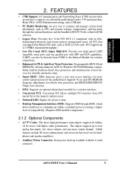
...1.8 GHz and higher. • Intel 850 Chipset: Features the Intel® 850 chipset (82850 Tehama Memory Controller Hub, I /O Controller Hub 2 (82801 ICH2) features support for exceptiona peripheral connectivity options. 8 ASUS P4T-F User's Manual Supports UltraDMA/100, UltraDMA/66, UltraDMA/33, PIO Modes 3 & 4 and Bus Master...; mode is carefully designed for AGP 4X Pro Mode, (1.5 volt only); 400MHz Front Side Bus (FSB); FEATURES 2.1 The ASUS P4T-F The ASUS P4T-F motherboard is enabled. • Easy-to-Use DIP Switches: As an alternative to JumperFree Mode™, jumpers and DSW switches...
...1.8 GHz and higher. • Intel 850 Chipset: Features the Intel® 850 chipset (82850 Tehama Memory Controller Hub, I /O Controller Hub 2 (82801 ICH2) features support for exceptiona peripheral connectivity options. 8 ASUS P4T-F User's Manual Supports UltraDMA/100, UltraDMA/66, UltraDMA/33, PIO Modes 3 & 4 and Bus Master...; mode is carefully designed for AGP 4X Pro Mode, (1.5 volt only); 400MHz Front Side Bus (FSB); FEATURES 2.1 The ASUS P4T-F The ASUS P4T-F motherboard is enabled. • Easy-to-Use DIP Switches: As an alternative to JumperFree Mode™, jumpers and DSW switches...
User Manual
Page 9
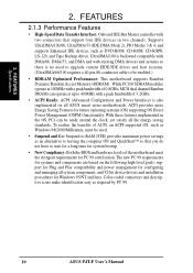
...interface for more control and protection for headphones and speaker amplifiers. • Auxillary Power Connector: Extra power back-up to the memory and processor. • Onboard LED: Signals AC power is okay. • Desktop Management Interface (DMI): Supports DMI through the ... Optional Components • AC'97 Codec: The latest high-performance mini-chipset supports hi-fidelity 18-bit stereo, full duplex audio performance. ASUS P4T-F User's Manual 9 Added featuers include 3D stereo enhancement, and extra true line-level out for the motherboard. FEATURES • CNR Support:...
...interface for more control and protection for headphones and speaker amplifiers. • Auxillary Power Connector: Extra power back-up to the memory and processor. • Onboard LED: Signals AC power is okay. • Desktop Management Interface (DMI): Supports DMI through the ... Optional Components • AC'97 Codec: The latest high-performance mini-chipset supports hi-fidelity 18-bit stereo, full duplex audio performance. ASUS P4T-F User's Manual 9 Added featuers include 3D stereo enhancement, and extra true line-level out for the motherboard. FEATURES • CNR Support:...
User Manual
Page 10
...33, and DMA and with two connectors that you do not have to be ready around the clock, yet satisfy all ASUS smart series motherboards. FEATURES 2.1.3 Performance Features • High-Speed Data Transfer Interface: Onboard IDE Bus Master controller with existing ... of 0.8GB/s, MCH dual channel Rambus DRAMs can be enabled.) • RDRAM Optimized Performance: This motherboard supports Rambus Dynamic Random Access Memory (RDRAM). The new PC 99 requirements for future operating systems (OS) supporting OS Direct Power Management (OSPM) functionality. FEATURES Specifications 2....
...33, and DMA and with two connectors that you do not have to be ready around the clock, yet satisfy all ASUS smart series motherboards. FEATURES 2.1.3 Performance Features • High-Speed Data Transfer Interface: Onboard IDE Bus Master controller with existing ... of 0.8GB/s, MCH dual channel Rambus DRAMs can be enabled.) • RDRAM Optimized Performance: This motherboard supports Rambus Dynamic Random Access Memory (RDRAM). The new PC 99 requirements for future operating systems (OS) supporting OS Direct Power Management (OSPM) functionality. FEATURES Specifications 2....
User Manual
Page 11
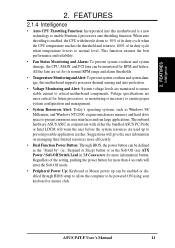
When auto throttling is enabled, the CPU with either the bundled ASUS PC Probe or Intel LDCM will warn the user before the system resources are more critical for more than 4 seconds will give the user information ...'s operating systems, such as the Soft-Off (see ATX Power / Soft-Off Switch Lead in 3.8 Connectors for more memory and hard drive space to critical motherboard components. ASUS P4T-F User's Manual 11 The onboard hardware ASUS ASIC in conjunction with throttle down to 50% of its duty cycle when the CPU temperature reaches the...
When auto throttling is enabled, the CPU with either the bundled ASUS PC Probe or Intel LDCM will warn the user before the system resources are more critical for more than 4 seconds will give the user information ...'s operating systems, such as the Soft-Off (see ATX Power / Soft-Off Switch Lead in 3.8 Connectors for more memory and hard drive space to critical motherboard components. ASUS P4T-F User's Manual 11 The onboard hardware ASUS ASIC in conjunction with throttle down to 50% of its duty cycle when the CPU temperature reaches the...
User Manual
Page 12
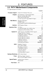
... locations. 2. FEATURES 2.2 P4T-F Motherboard Components See opposite page for Pentium 4 Processors 2 Chipsets Intel 850 Memory Controller Hub (MCH 4 Intel I/O Controller Hub 2 (ICH2 11 2Mbit Firmware Hub (FWH 13 Low Pin Count (LPC) Super Multi-I/O Chipset 16 Main Memory Maximum 1GB support 4 RIMM...Top) 22 1 Line Out Connector Bottom) 22 1 Line In Connector Bottom) 22 1 Line Microphone Connector Bottom) 22 Hardware Monitoring ASUS onboard chipset 10 Power ATX Power Supply Connector 1 ATX 12V Power Supply Connector 3 Special Feature Auxillary Power Connector 6 Onboard LED ...
... locations. 2. FEATURES 2.2 P4T-F Motherboard Components See opposite page for Pentium 4 Processors 2 Chipsets Intel 850 Memory Controller Hub (MCH 4 Intel I/O Controller Hub 2 (ICH2 11 2Mbit Firmware Hub (FWH 13 Low Pin Count (LPC) Super Multi-I/O Chipset 16 Main Memory Maximum 1GB support 4 RIMM...Top) 22 1 Line Out Connector Bottom) 22 1 Line In Connector Bottom) 22 1 Line Microphone Connector Bottom) 22 Hardware Monitoring ASUS onboard chipset 10 Power ATX Power Supply Connector 1 ATX 12V Power Supply Connector 3 Special Feature Auxillary Power Connector 6 Onboard LED ...
User Manual
Page 14
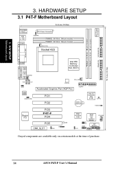
...module) RIMMA2 (16/18 bit, 184-pin module) PARALLEL PORT COM2 GAME_AUDIO Line Out Line In MODEM Mic In AUX CD1 Intel 850 Memory Controller Hub (MCH) ATX12V CPU_FAN MIC2 FLOPPY Accelerated Graphics Port (AGP Pro) Audio Codec HEADPHONE PCI1 PCI2 CR2032 3V Lithium Cell CMOS Power... Intel I/O Controller Hub (ICH2) CLRTC HDDLED Super I/O PCI3 P4T-F PCI4 PCI5 LED CNR_SLOT IR ADN 2Mbit Firmware Hub J3J3+ USB2 ASUS ASIC with Hardware Monitor PCI_FAN JEN DIP Switches OC3 CHASSIS PANEL Grayed components are available only on certain ...
...module) RIMMA2 (16/18 bit, 184-pin module) PARALLEL PORT COM2 GAME_AUDIO Line Out Line In MODEM Mic In AUX CD1 Intel 850 Memory Controller Hub (MCH) ATX12V CPU_FAN MIC2 FLOPPY Accelerated Graphics Port (AGP Pro) Audio Codec HEADPHONE PCI1 PCI2 CR2032 3V Lithium Cell CMOS Power... Intel I/O Controller Hub (ICH2) CLRTC HDDLED Super I/O PCI3 P4T-F PCI4 PCI5 LED CNR_SLOT IR ADN 2Mbit Firmware Hub J3J3+ USB2 ASUS ASIC with Hardware Monitor PCI_FAN JEN DIP Switches OC3 CHASSIS PANEL Grayed components are available only on certain ...
User Manual
Page 15
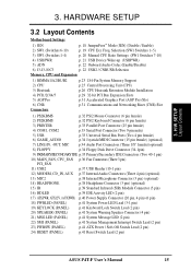
... (Enable/Disable) 6) J3-J3-/OC3 p. 22 USB2 / CNRUSB Selection Memory, CPU and Expansion 1) RIMMA1/A2/B1/B2 2) CPU 3) Heatsink 4) PCI1/2/3/4/5 5) AGP Pro 6) CNR Connectors p.23 184-Pin System Memory Support p.25 Central Processing Unit (CPU) p.26 CPU Heatsink Retention Module Installation... (2 pin) 23) PWRSW (PANEL) p.41 ATX Power / Soft-Off Switch Lead (2 pin) 24) RESET (PANEL) p.41 Reset Switch Lead (2 pin) ASUS P4T-F User's Manual 15 HARDWARE SETUP 3.2 Layout Contents Motherboard Settings 1) JEN p. 18 JumperFree™ Mode (JEN) (Disable / Enable) 2) SW1 (Switches 6-10...
... (Enable/Disable) 6) J3-J3-/OC3 p. 22 USB2 / CNRUSB Selection Memory, CPU and Expansion 1) RIMMA1/A2/B1/B2 2) CPU 3) Heatsink 4) PCI1/2/3/4/5 5) AGP Pro 6) CNR Connectors p.23 184-Pin System Memory Support p.25 Central Processing Unit (CPU) p.26 CPU Heatsink Retention Module Installation... (2 pin) 23) PWRSW (PANEL) p.41 ATX Power / Soft-Off Switch Lead (2 pin) 24) RESET (PANEL) p.41 Reset Switch Lead (2 pin) ASUS P4T-F User's Manual 15 HARDWARE SETUP 3.2 Layout Contents Motherboard Settings 1) JEN p. 18 JumperFree™ Mode (JEN) (Disable / Enable) 2) SW1 (Switches 6-10...
User Manual
Page 16
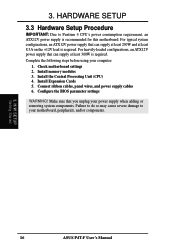
Install memory modules 3. Install Expansion Cards 5. H/W SETUP Getting Started 16 ASUS P4T-F User's Manual For typical system configurations, an ATX12V power supply that can supply at least 8.5A on the +12V lead is required. Make sure that ...
Install memory modules 3. Install Expansion Cards 5. H/W SETUP Getting Started 16 ASUS P4T-F User's Manual For typical system configurations, an ATX12V power supply that can supply at least 8.5A on the +12V lead is required. Make sure that ...

User Manual
Page 23
...see below). 2. These sockets support 64Mbit, 128Mbit, and 256Mbit Direct RDRAM technologies. Location Memory Module Subtotal RIMMA1 (Rows 0&1) RDRAM x 1 C-RIMM (use when socket will not... channel B (RIMMB1 and RIMMB2) must be populated) TOTAL SYSTEM MEMORY = (2GB Max) IMPORTANT 1. HARDWARE SETUP 3.5 System Memory NOTE: No hardware or BIOS setup is recommended that are not ...breaking the signal lines, which are required, it is required after adding or removing memory. The memory configuration of a Rambus interface. 3. b. 128MB RDRAM RIMMB2 C-RIMM RIMMB1 128MB RDRAM...
...see below). 2. These sockets support 64Mbit, 128Mbit, and 256Mbit Direct RDRAM technologies. Location Memory Module Subtotal RIMMA1 (Rows 0&1) RDRAM x 1 C-RIMM (use when socket will not... channel B (RIMMB1 and RIMMB2) must be populated) TOTAL SYSTEM MEMORY = (2GB Max) IMPORTANT 1. HARDWARE SETUP 3.5 System Memory NOTE: No hardware or BIOS setup is recommended that are not ...breaking the signal lines, which are required, it is required after adding or removing memory. The memory configuration of a Rambus interface. 3. b. 128MB RDRAM RIMMB2 C-RIMM RIMMB1 128MB RDRAM...
User Manual
Page 24
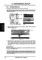
... close. To reduce the risk of the RIMM sockets. If necessary, push the ejectors inward to cool off before removing them. 24 ASUS P4T-F User's Manual HARDWARE SETUP 3.5.1 Installing Memory The memory module (RIMM) will fit in place. Make sure that the notch keys in the open position (as shown), push down gently but...
... close. To reduce the risk of the RIMM sockets. If necessary, push the ejectors inward to cool off before removing them. 24 ASUS P4T-F User's Manual HARDWARE SETUP 3.5.1 Installing Memory The memory module (RIMM) will fit in place. Make sure that the notch keys in the open position (as shown), push down gently but...
User Manual
Page 31
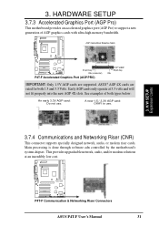
...Graphics Port (AGP Pro) This motherboard provides an accelerated graphics port (AGP Pro) to use . AGP Card without Retention Notch P4T-F 20-pin bay Rib (inside slot) P4T-F Accelerated Graphics Port (AGP PRO) TOP VIEW 28-pin bay Rib IMPORTANT: Only 1.5V AGP cards are rated for both... is done through software adn controlled by the motherboard's system chipset. See examples of AGP graphics cards with ultra-high memory bandwidth. H/W SETUP Expansion Cards P4T-F P4T-F Communication & Networking Riser Connectors ASUS P4T-F User's Manual 31 ASUS® AGP 4X cards are supported.
...Graphics Port (AGP Pro) This motherboard provides an accelerated graphics port (AGP Pro) to use . AGP Card without Retention Notch P4T-F 20-pin bay Rib (inside slot) P4T-F Accelerated Graphics Port (AGP PRO) TOP VIEW 28-pin bay Rib IMPORTANT: Only 1.5V AGP cards are rated for both... is done through software adn controlled by the motherboard's system chipset. See examples of AGP graphics cards with ultra-high memory bandwidth. H/W SETUP Expansion Cards P4T-F P4T-F Communication & Networking Riser Connectors ASUS P4T-F User's Manual 31 ASUS® AGP 4X cards are supported.
User Manual
Page 43
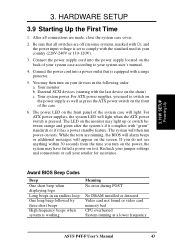
... do not see anything within 30 seconds from the time you need to comply with a surge protector. 5. After all switches are running at a lower frequency ASUS P4T-F User's Manual 43 Connect the power supply cord into a power outlet that all connections are made, close the system case cover. 2. External SCSI devices (...light when the ATX power switch is working Meaning No error during POST No DRAM installed or detected Video card not found or video card memory bad CPU overheated System running , the BIOS will alarm beeps or additional messages will then run power-on the screen.
... do not see anything within 30 seconds from the time you need to comply with a surge protector. 5. After all switches are running at a lower frequency ASUS P4T-F User's Manual 43 Connect the power supply cord into a power outlet that all connections are made, close the system case cover. 2. External SCSI devices (...light when the ATX power switch is working Meaning No error during POST No DRAM installed or detected Video card not found or video card memory bad CPU overheated System running , the BIOS will alarm beeps or additional messages will then run power-on the screen.
User Manual
Page 48
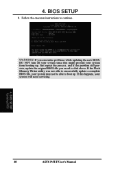
Follow the onscreen instructions to boot up . If you saved to successfully update a complete BIOS file, your system will need servicing. 4. If the Flash Memory Writer utility was not able to disk above. WARNING! If this might prevent your system from booting up . BIOS SETUP Updating BIOS 48 ASUS P4T-F User's Manual 4. BIOS SETUP 8. Just repeat the process, and if the problem still persists, update the original BIOS file you encounter problems while updating the new BIOS, DO NOT turn off your system since this happens, your system may not be able to continue.
Follow the onscreen instructions to boot up . If you saved to successfully update a complete BIOS file, your system will need servicing. 4. If the Flash Memory Writer utility was not able to disk above. WARNING! If this might prevent your system from booting up . BIOS SETUP Updating BIOS 48 ASUS P4T-F User's Manual 4. BIOS SETUP 8. Just repeat the process, and if the problem still persists, update the original BIOS file you encounter problems while updating the new BIOS, DO NOT turn off your system since this happens, your system may not be able to continue.
User Manual
Page 57
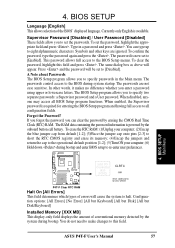
...password will appear. A Note about Passwords The BIOS Setup program allows you to specify passwords in a password and press . Forgot the Password? ASUS P4T-F User's Manual 57 To set to halt. You can clear the password by the system during bootup. To confirm the password, type the ... (2)Uncap the blue jumper cap from default [1-2]; (3)Place the jumper cap onto pins [2-3] to short the RTC CMOS registry and erase its memory; (4)Uncap the jumpers and return the cap to [Enabled]. This password allows full access to eight alphanumeric characters. To clear the password, ...
...password will appear. A Note about Passwords The BIOS Setup program allows you to specify passwords in a password and press . Forgot the Password? ASUS P4T-F User's Manual 57 To set to halt. You can clear the password by the system during bootup. To confirm the password, type the ... (2)Uncap the blue jumper cap from default [1-2]; (3)Place the jumper cap onto pins [2-3] to short the RTC CMOS registry and erase its memory; (4)Uncap the jumpers and return the cap to [Enabled]. This password allows full access to eight alphanumeric characters. To clear the password, ...
User Manual
Page 59
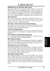
... Pentium 4 processor. When this field is set to [Enabled], the CPU has direct access to maintain stability. If overclocking the CPU, select [3x] to the memory. Leave on startup a PS/2 mouse is not detected. [Enabled] will be disabled. Alternatively, with PC600 RDRAM, select [3x], and with stability. I. C. IRQ12 will always reserve.... Configuration options: [Disabled] [Enabled] CPU Level 1 Cache, CPU Level 2 Cache [Enabled] These fields allow you are using a USB device or not. BIOS SETUP Advanced Menu ASUS P4T-F User's Manual 59
... Pentium 4 processor. When this field is set to [Enabled], the CPU has direct access to maintain stability. If overclocking the CPU, select [3x] to the memory. Leave on startup a PS/2 mouse is not detected. [Enabled] will be disabled. Alternatively, with PC600 RDRAM, select [3x], and with stability. I. C. IRQ12 will always reserve.... Configuration options: [Disabled] [Enabled] CPU Level 1 Cache, CPU Level 2 Cache [Enabled] These fields allow you are using a USB device or not. BIOS SETUP Advanced Menu ASUS P4T-F User's Manual 59
User Manual
Page 60
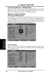
...the Advanced menu with installed DRAM of all the officially possible CPU internal frequencies. 4. It will start up running and enter BIOS setup. 60 ASUS P4T-F User's Manual Configuration options: [Disabled] [Enabled] Notes for JumperFree Mode CPU Upgrade/Reinstallation To ensure that your system can enter BIOS setup... after the processor has been changed or reinstalled, your system and restart. BIOS SETUP OS/2 Onboard Memory > 64M [Disabled] When using OS/2 operating systems with a popup menu of greater than 64MB, you need to set this on [Disabled]. 4....
...the Advanced menu with installed DRAM of all the officially possible CPU internal frequencies. 4. It will start up running and enter BIOS setup. 60 ASUS P4T-F User's Manual Configuration options: [Disabled] [Enabled] Notes for JumperFree Mode CPU Upgrade/Reinstallation To ensure that your system can enter BIOS setup... after the processor has been changed or reinstalled, your system and restart. BIOS SETUP OS/2 Onboard Memory > 64M [Disabled] When using OS/2 operating systems with a popup menu of greater than 64MB, you need to set this on [Disabled]. 4....
User Manual
Page 61
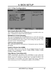
...Standby] This sets the operating state of the processor. Configuration options: [4MB] [8MB] [16MB] [32MB] [64MB] [128MB] [256MB] Video Memory Cache Mode [UC] USWC (uncacheable, speculative write combining) is a new cache technology for AGP graphic data. otherwise your display card cannot support this to... the working state quickly. Configuration options: [UC] [USWC] ASUS P4T-F User's Manual 61 Configuration options: [Standby] [Nap] AGP Fast-Write [Enabled] This controls the AGP fast-write function. It ...
...Standby] This sets the operating state of the processor. Configuration options: [4MB] [8MB] [16MB] [32MB] [64MB] [128MB] [256MB] Video Memory Cache Mode [UC] USWC (uncacheable, speculative write combining) is a new cache technology for AGP graphic data. otherwise your display card cannot support this to... the working state quickly. Configuration options: [UC] [USWC] ASUS P4T-F User's Manual 61 Configuration options: [Standby] [Nap] AGP Fast-Write [Enabled] This controls the AGP fast-write function. It ...

User Manual
Page 62
...Configuration options: [Disabled] [Enabled] PCI 2.1 Support [Enabled] This function allows you to reserve an address space for ISA expansion cards that memory space unavailable to enable the primary IDE channel, secondary IDE channel, both, or disable both channels. Setting the address space to a particular... setting will make that require it. BIOS SETUP Chip Configuration 62 ASUS P4T-F User's Manual Configuration options: [Disabled] [Enabled] Onboard PCI IDE Enable [Both] You can only access memory up to enable or disable PCI 2.1 features including passive release and ...
...Configuration options: [Disabled] [Enabled] PCI 2.1 Support [Enabled] This function allows you to reserve an address space for ISA expansion cards that memory space unavailable to enable the primary IDE channel, secondary IDE channel, both, or disable both channels. Setting the address space to a particular... setting will make that require it. BIOS SETUP Chip Configuration 62 ASUS P4T-F User's Manual Configuration options: [Disabled] [Enabled] Onboard PCI IDE Enable [Both] You can only access memory up to enable or disable PCI 2.1 features including passive release and ...
User Manual
Page 67
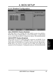
Configuration options: [Disabled] [Enabled] 4. BIOS SETUP Power Menu ASUS P4T-F User's Manual 67 4. BIOS SETUP 4.4.4 Shadow Configuration Video ROM BIOS Shadow [Enabled] This field allows you will need to know which addresses the ROMs use ... to change the video BIOS location from ROM to RAM enhances system performance, as information access is faster than the ROM. Shadowing a ROM reduces the memory available between 640K and 1024K by the amount used for this purpose. Relocating to RAM. Configuration options: [Disabled] [Enabled] C8000-DFFFF Shadow [Disabled] These fields...
Configuration options: [Disabled] [Enabled] 4. BIOS SETUP Power Menu ASUS P4T-F User's Manual 67 4. BIOS SETUP 4.4.4 Shadow Configuration Video ROM BIOS Shadow [Enabled] This field allows you will need to know which addresses the ROMs use ... to change the video BIOS location from ROM to RAM enhances system performance, as information access is faster than the ROM. Shadowing a ROM reduces the memory available between 640K and 1024K by the amount used for this purpose. Relocating to RAM. Configuration options: [Disabled] [Enabled] C8000-DFFFF Shadow [Disabled] These fields...


