Motherboard DIY Troubleshooting Guide
Page 8
... the motherboard and the new technology it supports. • Chapter 2: Hardware information This chapter lists the hardware setup procedures that you need when installing the ASUS P4B-MX motherboard. It includes description of the switches, jumpers, and connectors on the motherboard. • Chapter 3: Powering up This chapter describes the power up sequence and... the topics found in this guide is organized This manual contains the following parts: • Chapter 1: Product introduction This chapter describes the features of the P4B-MX motherboard.
... the motherboard and the new technology it supports. • Chapter 2: Hardware information This chapter lists the hardware setup procedures that you need when installing the ASUS P4B-MX motherboard. It includes description of the switches, jumpers, and connectors on the motherboard. • Chapter 3: Powering up This chapter describes the power up sequence and... the topics found in this guide is organized This manual contains the following parts: • Chapter 1: Product introduction This chapter describes the features of the P4B-MX motherboard.

Motherboard DIY Troubleshooting Guide
Page 12
ASUS P4B-MX motherboard
ASUS P4B-MX motherboard

Motherboard DIY Troubleshooting Guide
Page 13
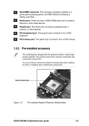
...technology making it , check the items in your package with the Intel® 845 (Brookdale) chipset to get ahead in ) ASUS P4B-MX support CD ASUS 2-port USB module 80-conductor ribbon cable for UltraDMA/33/66/100 IDE drives Ribbon cable for a 3.5-inch floppy drive Bag ...the ATA100 protocol, and AC '97-compliant audio features, the P4B-MX is damaged or missing, contact your P4B-MX package for the following items. ASUS P4B-MX motherboard (micro-ATX form factor: 9.6-in x 9.6-in the world of ASUS quality motherboards! The P4B-MX incorporates the Intel® Pentium® 4 Processor in 478-...
...technology making it , check the items in your package with the Intel® 845 (Brookdale) chipset to get ahead in ) ASUS P4B-MX support CD ASUS 2-port USB module 80-conductor ribbon cable for UltraDMA/33/66/100 IDE drives Ribbon cable for a 3.5-inch floppy drive Bag ...the ATA100 protocol, and AC '97-compliant audio features, the P4B-MX is damaged or missing, contact your P4B-MX package for the following items. ASUS P4B-MX motherboard (micro-ATX form factor: 9.6-in x 9.6-in the world of ASUS quality motherboards! The P4B-MX incorporates the Intel® Pentium® 4 Processor in 478-...
Motherboard DIY Troubleshooting Guide
Page 15
... 1A on the +5V standby lead (+5VSB). 6 IDE connectors. Both the primary (blue) and secondary (black) connectors are interconnected through the Intel proprietary Hub interface. ASUS P4B-MX motherboard user guide 1-3 A 478-pin surface mount, Zero Insertion Force (ZIF) socket called the Intel Memory Controller Hub (MCH) is slotted to prevent incorrect insertion...
... 1A on the +5V standby lead (+5VSB). 6 IDE connectors. Both the primary (blue) and secondary (black) connectors are interconnected through the Intel proprietary Hub interface. ASUS P4B-MX motherboard user guide 1-3 A 478-pin surface mount, Zero Insertion Force (ZIF) socket called the Intel Memory Controller Hub (MCH) is slotted to prevent incorrect insertion...
Motherboard DIY Troubleshooting Guide
Page 17
.... 1.3.2 Pre-installed accessory This motherboard is for playing or editing audio files. 23 Serial ports. Retention Module Base Figure 1-2 Pre-installed Heatsink Retention Module Base ASUS P4B-MX motherboard user guide 1-5 22 Game/MIDI connector. This module should fit the retention mechanism that comes with the heatsink retention module base already installed. This...
.... 1.3.2 Pre-installed accessory This motherboard is for playing or editing audio files. 23 Serial ports. Retention Module Base Figure 1-2 Pre-installed Heatsink Retention Module Base ASUS P4B-MX motherboard user guide 1-5 22 Game/MIDI connector. This module should fit the retention mechanism that comes with the heatsink retention module base already installed. This...

Motherboard DIY Troubleshooting Guide
Page 20
ASUS P4B-MX motherboard
ASUS P4B-MX motherboard

Motherboard DIY Troubleshooting Guide
Page 21
Refer to the rear part of the chassis Figure 2-1 Motherboard placement and screw holes ASUS P4B-MX motherboard user guide 2-1 Place this side towards the rear of the chassis. 2.1 Motherboard installation Before you place it . The edge with external ports goes to ... Place eight (8) screws into the chassis in the correct orientation. Do not overtighten the screws! Make sure to do so may damage the motherboard. The P4B-MX uses the microATX form factor that the motherboard fits into it into the holes indicated by circles to secure the motherboard to ensure that measures...
Refer to the rear part of the chassis Figure 2-1 Motherboard placement and screw holes ASUS P4B-MX motherboard user guide 2-1 Place this side towards the rear of the chassis. 2.1 Motherboard installation Before you place it . The edge with external ports goes to ... Place eight (8) screws into the chassis in the correct orientation. Do not overtighten the screws! Make sure to do so may damage the motherboard. The P4B-MX uses the microATX form factor that the motherboard fits into it into the holes indicated by circles to secure the motherboard to ensure that measures...

Motherboard DIY Troubleshooting Guide
Page 23
... any motherboard settings. 1. When lit, the onboard LED indicates that came with the component. 5. See the illustration below. ® P4B-MX P4B-MX Onboard LED Figure 2-3 Onboard Power LED ON Standby Power OFF Powered Off ASUS P4B-MX motherboard user guide 2-3 Use a grounded wrist strap or touch a safely grounded object or to a metal object, such as the...
... any motherboard settings. 1. When lit, the onboard LED indicates that came with the component. 5. See the illustration below. ® P4B-MX P4B-MX Onboard LED Figure 2-3 Onboard Power LED ON Standby Power OFF Powered Off ASUS P4B-MX motherboard user guide 2-3 Use a grounded wrist strap or touch a safely grounded object or to a metal object, such as the...

Motherboard DIY Troubleshooting Guide
Page 25
2.4.2 Installing the CPU Follow these steps to a 90°-100° angle. ASUS P4B-MX motherboard user guide 2-5 Unlock the socket by pressing the lever sideways, then lift it up to 90°-100° angle, otherwise the CPU does not fit in completely. Socket Lever 90 - 100 Figure 2-6 CPU Socket Lever at 90° -100° Angle Make sure that the socket lever is lifted up to install a CPU. 1. Figure 2-5 Intel 478-pin ZIF Socket 2. Locate the 478-pin ZIF socket on the motherboard.
2.4.2 Installing the CPU Follow these steps to a 90°-100° angle. ASUS P4B-MX motherboard user guide 2-5 Unlock the socket by pressing the lever sideways, then lift it up to 90°-100° angle, otherwise the CPU does not fit in completely. Socket Lever 90 - 100 Figure 2-6 CPU Socket Lever at 90° -100° Angle Make sure that the socket lever is lifted up to install a CPU. 1. Figure 2-5 Intel 478-pin ZIF Socket 2. Locate the 478-pin ZIF socket on the motherboard.
Motherboard DIY Troubleshooting Guide
Page 27
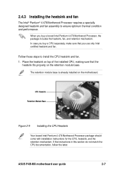
... installation instructions for the CPU, heatsink, and the retention mechanism. If the instructions in this section do not match the CPU documentation, follow the latter. ASUS P4B-MX motherboard user guide 2-7 When you buy a CPU separately, make sure that the heatsink fits properly on the motherboard. In case you use only Intel certified...
... installation instructions for the CPU, heatsink, and the retention mechanism. If the instructions in this section do not match the CPU documentation, follow the latter. ASUS P4B-MX motherboard user guide 2-7 When you buy a CPU separately, make sure that the heatsink fits properly on the motherboard. In case you use only Intel certified...
Motherboard DIY Troubleshooting Guide
Page 29
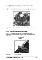
Push down the locks on the retention mechanism to secure the heatsink and fan to the connector on the motherboard labeled CPU_FAN. CPU Fan Connector (CPU_FAN) Figure 2-12 CPU Fan Connector ASUS P4B-MX motherboard user guide 2-9 3. Figure 2-11 Fan and Retention Mechanism Installed and Locked 2.4.4 Connecting the CPU fan cable When the fan, heatsink, and the retention mechanism are in place, connect the CPU fan cable to the module base. When secure, the retention locks should point to opposite directions.
Push down the locks on the retention mechanism to secure the heatsink and fan to the connector on the motherboard labeled CPU_FAN. CPU Fan Connector (CPU_FAN) Figure 2-12 CPU Fan Connector ASUS P4B-MX motherboard user guide 2-9 3. Figure 2-11 Fan and Retention Mechanism Installed and Locked 2.4.4 Connecting the CPU fan cable When the fan, heatsink, and the retention mechanism are in place, connect the CPU fan cable to the module base. When secure, the retention locks should point to opposite directions.
Motherboard DIY Troubleshooting Guide
Page 31
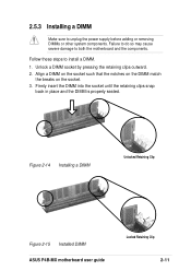
... to unplug the power supply before adding or removing DIMMs or other system components. Figure 2-14 Installing a DIMM Unlocked Retaining Clip Figure 2-15 Installed DIMM ASUS P4B-MX motherboard user guide Locked Retaining Clip 2-11 Failure to do so may cause severe damage to both the motherboard and the components.
... to unplug the power supply before adding or removing DIMMs or other system components. Figure 2-14 Installing a DIMM Unlocked Retaining Clip Figure 2-15 Installed DIMM ASUS P4B-MX motherboard user guide Locked Retaining Clip 2-11 Failure to do so may cause severe damage to both the motherboard and the components.
Motherboard DIY Troubleshooting Guide
Page 33
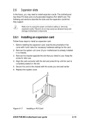
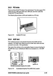
... cover. Make sure to the chassis with the slot and press firmly until the card is already installed in a chassis). 3. Figure 2-17 Installing a PCI Card ASUS P4B-MX motherboard user guide 2-13 Failure to do so may need to install expansion cards. 2.6 Expansion slots In the future, you may cause you physical injury...
... cover. Make sure to the chassis with the slot and press firmly until the card is already installed in a chassis). 3. Figure 2-17 Installing a PCI Card ASUS P4B-MX motherboard user guide 2-13 Failure to do so may need to install expansion cards. 2.6 Expansion slots In the future, you may cause you physical injury...
Motherboard DIY Troubleshooting Guide
Page 35
...buy an AGP card, make sure that comply with +1.5V specification. When you ask for 1.5V Figure 2-19 Accelerated Graphics Port (AGP) Slot Location ASUS P4B-MX motherboard user guide 2-15 Figure 2-18 Installed PCI Card 2.6.4 AGP slot This motherboard has an Accelerated Graphics Port (AGP) slot that they fit the...shows a LAN card installed on the card golden fingers to ensure that supports +1.5V AGP cards. Take note of a +1.5V AGP card. ® P4B-MX P4B-MX Accelerated Graphics Port (AGP) Keyed for one with PCI specifications. Below is an example of the notches on a PCI slot.
...buy an AGP card, make sure that comply with +1.5V specification. When you ask for 1.5V Figure 2-19 Accelerated Graphics Port (AGP) Slot Location ASUS P4B-MX motherboard user guide 2-15 Figure 2-18 Installed PCI Card 2.6.4 AGP slot This motherboard has an Accelerated Graphics Port (AGP) slot that they fit the...shows a LAN card installed on the card golden fingers to ensure that supports +1.5V AGP cards. Take note of a +1.5V AGP card. ® P4B-MX P4B-MX Accelerated Graphics Port (AGP) Keyed for one with PCI specifications. Below is an example of the notches on a PCI slot.
Motherboard DIY Troubleshooting Guide
Page 37
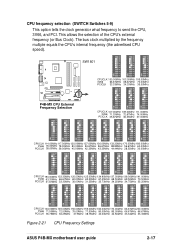
... multiple equals the CPU's internal frequency (the advertised CPU speed). SW1801 ON 1 2 3 4 5 6 7 8 9 10 ON 1 2 3 4 5 6 7 8 9 10 ON 1 2 3 4 5 6 7 8 9 10 ® P4B-MX P4B-MX CPU External Frequency Selection CPUCLK 100.00MHz 103.00MHz 105.00MHz 3V66 66.67MHz 68.67MHz 70.00MHz PCICLK 33.33MHz 34.33MHz 35.00MHz ....67MHz PCICLK 35.75MHz 36.25MHz 37.5MHz 38.75MHz 40.00MHz 42.50MHz 33.34MHz 33.33MHz Figure 2-21 CPU Frequency Settings ASUS P4B-MX motherboard user guide 2-17 CPU frequency selection (SWITCH Switches 5-9) This option tells the clock generator what frequency to send the CPU, ...
... multiple equals the CPU's internal frequency (the advertised CPU speed). SW1801 ON 1 2 3 4 5 6 7 8 9 10 ON 1 2 3 4 5 6 7 8 9 10 ON 1 2 3 4 5 6 7 8 9 10 ® P4B-MX P4B-MX CPU External Frequency Selection CPUCLK 100.00MHz 103.00MHz 105.00MHz 3V66 66.67MHz 68.67MHz 70.00MHz PCICLK 33.33MHz 34.33MHz 35.00MHz ....67MHz PCICLK 35.75MHz 36.25MHz 37.5MHz 38.75MHz 40.00MHz 42.50MHz 33.34MHz 33.33MHz Figure 2-21 CPU Frequency Settings ASUS P4B-MX motherboard user guide 2-17 CPU frequency selection (SWITCH Switches 5-9) This option tells the clock generator what frequency to send the CPU, ...
Motherboard DIY Troubleshooting Guide
Page 39
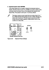
... current consumed must NOT exceed the power supply capability (+5VSB) whether under normal condition or in sleep mode. ® P4B-MX KBPWR 2 1 +5V (Default) 3 2 +5VSB P4B-MX Keyboard Power Up Figure 2-23 Keyboard Power Settings ASUS P4B-MX motherboard user guide 2-19 Otherwise, the system does not power up the computer when you to wake up . This...
... current consumed must NOT exceed the power supply capability (+5VSB) whether under normal condition or in sleep mode. ® P4B-MX KBPWR 2 1 +5V (Default) 3 2 +5VSB P4B-MX Keyboard Power Up Figure 2-23 Keyboard Power Settings ASUS P4B-MX motherboard user guide 2-19 Otherwise, the system does not power up the computer when you to wake up . This...

Motherboard DIY Troubleshooting Guide
Page 41
Always connect ribbon cables with the red stripe to light up. ® P4B-MX TIP: If the case-mounted LED does not light up, try reversing the 2-pin plug. The read or write activities of any device connected to ... drives. 1. Doing so may be on the opposite side on the side closest to the hard disk activity LED. HDDLED P4B-MX HDD Activity LED Figure 2-25 Hard Disk LED Connector ASUS P4B-MX motherboard user guide 2-21 2.8 Connectors This section describes and illustrates the internal connectors on hard drives and CD-ROM drives, but...
Always connect ribbon cables with the red stripe to light up. ® P4B-MX TIP: If the case-mounted LED does not light up, try reversing the 2-pin plug. The read or write activities of any device connected to ... drives. 1. Doing so may be on the opposite side on the side closest to the hard disk activity LED. HDDLED P4B-MX HDD Activity LED Figure 2-25 Hard Disk LED Connector ASUS P4B-MX motherboard user guide 2-21 2.8 Connectors This section describes and illustrates the internal connectors on hard drives and CD-ROM drives, but...

Motherboard DIY Troubleshooting Guide
Page 43
...34-1 pin FLOPPY) This connector supports the provided floppy drive ribbon cable. Lack of the expansion slots. CPU_FAN Rotation +12V- ® P4B-MX SYSTEM_FAN Rotation -+12V PCI_FAN Rotation +12V- 3. Do not forget to connect the fan cables to prevent incorrect insertion when using ribbon cables .... Connect the fan cable to the connector matching the black wire to PIN 1. ® P4B-MX P4B-MX Floppy Disk Drive Connector Figure 2-27 Floppy Disk Drive Connector 4. P4B-MX 12-Volt Cooling Fan Power Figure 2-28 CPU, System, and PCI Fan Connectors ASUS P4B-MX motherboard user guide 2-23
...34-1 pin FLOPPY) This connector supports the provided floppy drive ribbon cable. Lack of the expansion slots. CPU_FAN Rotation +12V- ® P4B-MX SYSTEM_FAN Rotation -+12V PCI_FAN Rotation +12V- 3. Do not forget to connect the fan cables to prevent incorrect insertion when using ribbon cables .... Connect the fan cable to the connector matching the black wire to PIN 1. ® P4B-MX P4B-MX Floppy Disk Drive Connector Figure 2-27 Floppy Disk Drive Connector 4. P4B-MX 12-Volt Cooling Fan Power Figure 2-28 CPU, System, and PCI Fan Connectors ASUS P4B-MX motherboard user guide 2-23
Motherboard DIY Troubleshooting Guide
Page 45
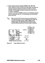
... +5.0VDC COM +3.3VDC +3.3VDC +5.0VDC +5.0VDC -5.0VDC COM COM COM PS_ON# COM -12.0VDC +3.3VDC ® P4B-MX P4B-MX ATX Power Connectors ATX +12V +12V DC COM Pin 1 +12V DC COM Figure 2-31 Power Supply Connectors ASUS P4B-MX motherboard user guide 2-25 Find the proper orientation and push down firmly until the connectors completely fit...
... +5.0VDC COM +3.3VDC +3.3VDC +5.0VDC +5.0VDC -5.0VDC COM COM COM PS_ON# COM -12.0VDC +3.3VDC ® P4B-MX P4B-MX ATX Power Connectors ATX +12V +12V DC COM Pin 1 +12V DC COM Figure 2-31 Power Supply Connectors ASUS P4B-MX motherboard user guide 2-25 Find the proper orientation and push down firmly until the connectors completely fit...
Motherboard DIY Troubleshooting Guide
Page 47
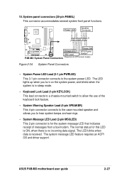
... PLED Keylock +5V Ground Ground Speaker 20 1 +5 VSB MLED ExtSMI# Ground PWR Ground Reset Ground Reset SW ® P4B-MX Message LED ATX Power SMI Lead Switch* P4B-MX System Panel Connectors * Requires an ATX power supply. Figure 2-34 System Panel Connectors • System Power LED Lead (3-1 pin... switch to allow the use of messages from a fax/modem. The system message LED feature requires an ACPI OS and driver support. ASUS P4B-MX motherboard user guide 2-27 The normal status for the system message LED that indicates receipt of the keyboard lock feature. • System ...
... PLED Keylock +5V Ground Ground Speaker 20 1 +5 VSB MLED ExtSMI# Ground PWR Ground Reset Ground Reset SW ® P4B-MX Message LED ATX Power SMI Lead Switch* P4B-MX System Panel Connectors * Requires an ATX power supply. Figure 2-34 System Panel Connectors • System Power LED Lead (3-1 pin... switch to allow the use of messages from a fax/modem. The system message LED feature requires an ACPI OS and driver support. ASUS P4B-MX motherboard user guide 2-27 The normal status for the system message LED that indicates receipt of the keyboard lock feature. • System ...


