
Motherboard DIY Troubleshooting Guide
Page 13
... ) ASUS P4B-MX support CD ASUS 2-port USB module 80-conductor ribbon cable for UltraDMA/33/66/100 IDE drives Ribbon cable for a 3.5-inch floppy drive Bag of extra jumper caps User Guide If any of the above items is your retailer. Supporting up to 3GB of system memory with the Intel® 845 (Brookdale) chipset to get ahead in the long line of power computing! ASUS P4B-MX motherboard user guide 1-1 Before you for an effective desktop...
... ) ASUS P4B-MX support CD ASUS 2-port USB module 80-conductor ribbon cable for UltraDMA/33/66/100 IDE drives Ribbon cable for a 3.5-inch floppy drive Bag of extra jumper caps User Guide If any of the above items is your retailer. Supporting up to 3GB of system memory with the Intel® 845 (Brookdale) chipset to get ahead in the long line of power computing! ASUS P4B-MX motherboard user guide 1-1 Before you for an effective desktop...
Motherboard DIY Troubleshooting Guide
Page 15
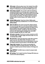
... compatible with 400MHz system bus. 2 North bridge controller. This connector accommodates the provided ribbon cable for the floppy disk drive. ASUS P4B-MX motherboard user guide 1-3 A 478-pin surface mount, Zero Insertion Force (ZIF) socket called the Intel Memory Controller Hub (MCH) is slotted to four Ultra DMA/100/66, PIO Modes 3 & 4 IDE devices. This socket accommodates the Intel® Pentium® 4 478/Northwood Processor with MPU-401 UART mode. 5 ATX power connector. This 20-pin connector connects to set the CPU external frequency...
... compatible with 400MHz system bus. 2 North bridge controller. This connector accommodates the provided ribbon cable for the floppy disk drive. ASUS P4B-MX motherboard user guide 1-3 A 478-pin surface mount, Zero Insertion Force (ZIF) socket called the Intel Memory Controller Hub (MCH) is slotted to four Ultra DMA/100/66, PIO Modes 3 & 4 IDE devices. This socket accommodates the Intel® Pentium® 4 478/Northwood Processor with MPU-401 UART mode. 5 ATX power connector. This 20-pin connector connects to set the CPU external frequency...
Motherboard DIY Troubleshooting Guide
Page 16
... provides stereo analog I /O subsystem that allows 10BASE-T and 100BASE-TX networking capabilities, and provides the LAN solution to as power amplifiers and programmable gain blocks. 14 PCI slots. This power connector connects the 4-pin 12V plug from the ATX 12V power supply. 17 USB ports. This port allows connection to turn off the system power before plugging or unplugging devices. 13 Audio CODEC. In 6-channel mode, the function of this controller provides the I /O on the motherboard.
... provides stereo analog I /O subsystem that allows 10BASE-T and 100BASE-TX networking capabilities, and provides the LAN solution to as power amplifiers and programmable gain blocks. 14 PCI slots. This power connector connects the 4-pin 12V plug from the ATX 12V power supply. 17 USB ports. This port allows connection to turn off the system power before plugging or unplugging devices. 13 Audio CODEC. In 6-channel mode, the function of this controller provides the I /O on the motherboard.
Motherboard DIY Troubleshooting Guide
Page 34
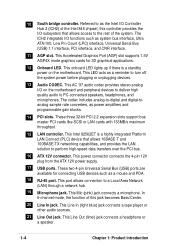
...- Onboard USB controller HC0 - - - Onboard USB controller HC1 shared AGP shared Onboard Audio - See Chapter 4 for this motherboard A B C D E F G H PCI slot 1 - - - - - Standard Interrupt Assignments IRQ Priority Standard Function 0 1 System Timer 1 2 Keyboard Controller 2 N/A Programmable Interrupt 3* 11 Communications Port (COM2) 4* 12 Communications Port (COM1) 5* 13 Sound Card (sometimes LPT2) 6 14 Floppy Disk Controller 7* 15 Printer Port (LPT1) 8 3 System CMOS/Real Time Clock 9* 4 ACPI Mode when used 10* 5 IRQ Holder for PCI Steering...
...- Onboard USB controller HC0 - - - Onboard USB controller HC1 shared AGP shared Onboard Audio - See Chapter 4 for this motherboard A B C D E F G H PCI slot 1 - - - - - Standard Interrupt Assignments IRQ Priority Standard Function 0 1 System Timer 1 2 Keyboard Controller 2 N/A Programmable Interrupt 3* 11 Communications Port (COM2) 4* 12 Communications Port (COM1) 5* 13 Sound Card (sometimes LPT2) 6 14 Floppy Disk Controller 7* 15 Printer Port (LPT1) 8 3 System CMOS/Real Time Clock 9* 4 ACPI Mode when used 10* 5 IRQ Holder for PCI Steering...
Motherboard DIY Troubleshooting Guide
Page 35
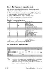
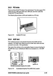
... ensure that you buy an AGP card, make sure that they fit the AGP slot on a PCI slot. The slots support PCI cards such as a LAN card, SCSI card, USB card, and other cards that supports +1.5V AGP cards. When you ask for 1.5V Figure 2-19 Accelerated Graphics Port (AGP) Slot Location ASUS P4B-MX motherboard user guide 2-15 The following figure shows a LAN card installed on your motherboard. Take note of a +1.5V AGP card. ® P4B-MX P4B-MX Accelerated Graphics Port (AGP) Keyed for one with PCI specifications.
... ensure that you buy an AGP card, make sure that they fit the AGP slot on a PCI slot. The slots support PCI cards such as a LAN card, SCSI card, USB card, and other cards that supports +1.5V AGP cards. When you ask for 1.5V Figure 2-19 Accelerated Graphics Port (AGP) Slot Location ASUS P4B-MX motherboard user guide 2-15 The following figure shows a LAN card installed on your motherboard. Take note of a +1.5V AGP card. ® P4B-MX P4B-MX Accelerated Graphics Port (AGP) Keyed for one with PCI specifications.
Motherboard DIY Troubleshooting Guide
Page 37
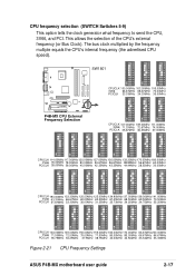
...ON 1 2 3 4 5 6 7 8 9 10 ON 1 2 3 4 5 6 7 8 9 10 ® P4B-MX P4B-MX CPU External Frequency Selection CPUCLK 100.00MHz 103.00MHz 105.00MHz 3V66 66.67MHz 68.67MHz 70.00MHz PCICLK 33.33MHz 34.33MHz 35.00MHz ON 1 ...CPU Frequency Settings ASUS P4B-MX motherboard user guide 2-17 The bus clock multiplied by the frequency multiple equals the CPU's internal frequency (the advertised CPU speed). CPU frequency selection (SWITCH Switches 5-9) This option tells the clock generator what frequency to send the CPU, 3V66, and PCI. This allows the selection of the CPU's external frequency (or Bus Clock...
...ON 1 2 3 4 5 6 7 8 9 10 ON 1 2 3 4 5 6 7 8 9 10 ® P4B-MX P4B-MX CPU External Frequency Selection CPUCLK 100.00MHz 103.00MHz 105.00MHz 3V66 66.67MHz 68.67MHz 70.00MHz PCICLK 33.33MHz 34.33MHz 35.00MHz ON 1 ...CPU Frequency Settings ASUS P4B-MX motherboard user guide 2-17 The bus clock multiplied by the frequency multiple equals the CPU's internal frequency (the advertised CPU speed). CPU frequency selection (SWITCH Switches 5-9) This option tells the clock generator what frequency to send the CPU, 3V66, and PCI. This allows the selection of the CPU's external frequency (or Bus Clock...
Motherboard DIY Troubleshooting Guide
Page 39
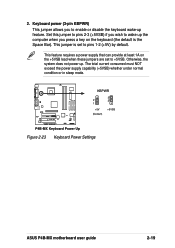
... 1A on the keyboard (the default is set to enable or disable the keyboard wake-up . 2. Set this jumper to pins 2-3 (+5VSB) if you wish to wake up the computer when you to +5VSB. The total current consumed must NOT exceed the power supply capability (+5VSB) whether under normal condition or in sleep mode. ® P4B-MX KBPWR 2 1 +5V (Default) 3 2 +5VSB P4B-MX Keyboard Power Up Figure 2-23 Keyboard Power Settings ASUS P4B-MX motherboard user guide 2-19 This jumper is the...
... 1A on the keyboard (the default is set to enable or disable the keyboard wake-up . 2. Set this jumper to pins 2-3 (+5VSB) if you wish to wake up the computer when you to +5VSB. The total current consumed must NOT exceed the power supply capability (+5VSB) whether under normal condition or in sleep mode. ® P4B-MX KBPWR 2 1 +5V (Default) 3 2 +5VSB P4B-MX Keyboard Power Up Figure 2-23 Keyboard Power Settings ASUS P4B-MX motherboard user guide 2-19 This jumper is the...

Motherboard DIY Troubleshooting Guide
Page 42
... connector supports the provided UltraDMA/100/66 IDE hard disk ribbon cable. If you install two hard disks, you connect the cables. 2. Secondary IDE Connector Primary IDE Connector ® P4B-MX P4B-MX IDE Connectors Figure 2-26 IDE Connectors NOTE: Orient the red markings (usually zigzag) on the UltraDMA cable connector. BIOS supports specific device bootup. This prevents incorrect orientation when you must configure the second drive as a slave device by setting its jumper accordingly. The UltraDMA/66 cable included in the motherboard package also supports UltraDMA...
... connector supports the provided UltraDMA/100/66 IDE hard disk ribbon cable. If you install two hard disks, you connect the cables. 2. Secondary IDE Connector Primary IDE Connector ® P4B-MX P4B-MX IDE Connectors Figure 2-26 IDE Connectors NOTE: Orient the red markings (usually zigzag) on the UltraDMA cable connector. BIOS supports specific device bootup. This prevents incorrect orientation when you must configure the second drive as a slave device by setting its jumper accordingly. The UltraDMA/66 cable included in the motherboard package also supports UltraDMA...
Motherboard DIY Troubleshooting Guide
Page 47
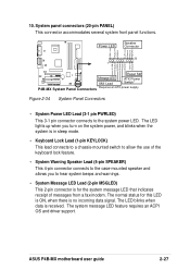
... is in sleep mode. • Keyboard Lock Lead (1-pin KEYLOCK) This lead connects to a chassis-mounted switch to allow the use of messages from a fax/modem. 10. The LED lights up when you turn on the system power, and blinks when the system is received. The system message LED feature requires an ACPI OS and driver support. ASUS P4B-MX motherboard user guide 2-27 System panel connectors (20-pin PANEL) This connector accommodates several system front panel functions.
... is in sleep mode. • Keyboard Lock Lead (1-pin KEYLOCK) This lead connects to a chassis-mounted switch to allow the use of messages from a fax/modem. 10. The LED lights up when you turn on the system power, and blinks when the system is received. The system message LED feature requires an ACPI OS and driver support. ASUS P4B-MX motherboard user guide 2-27 System panel connectors (20-pin PANEL) This connector accommodates several system front panel functions.

Motherboard DIY Troubleshooting Guide
Page 51
... 4. Turn on the screen. Award BIOS Beep Codes Beep One short beep when displaying logo Long beeps in an endless loop One long beep followed by three short beeps High frequency beeps when system is equipped with a surge protector. 5. The system then runs the power-on . Be sure that is working Meaning No error during POST No DRAM installed or detected Video card not found or video card memory bad CPU overheated; For ATX power supplies, the system LED lights up . While the tests are using an ATX power supply...
... 4. Turn on the screen. Award BIOS Beep Codes Beep One short beep when displaying logo Long beeps in an endless loop One long beep followed by three short beeps High frequency beeps when system is equipped with a surge protector. 5. The system then runs the power-on . Be sure that is working Meaning No error during POST No DRAM installed or detected Video card not found or video card memory bad CPU overheated; For ATX power supplies, the system LED lights up . While the tests are using an ATX power supply...
Motherboard DIY Troubleshooting Guide
Page 55
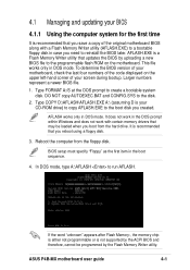
... original motherboard BIOS along with a Flash Memory Writer utility (AFLASH.EXE) to a bootable floppy disk in the boot sequence. 4. If the word "unknown" appears after Flash Memory:, the memory chip is either not programmable or is not supported by the ACPI BIOS and therefore, cannot be loaded when you reboot using a floppy disk. 3. AFLASH.EXE is recommended that updates the BIOS by the Flash Memory Writer utility. This file works only in DOS mode. In DOS mode, type A:\AFLASH...
... original motherboard BIOS along with a Flash Memory Writer utility (AFLASH.EXE) to a bootable floppy disk in the boot sequence. 4. If the word "unknown" appears after Flash Memory:, the memory chip is either not programmable or is not supported by the ACPI BIOS and therefore, cannot be loaded when you reboot using a floppy disk. 3. AFLASH.EXE is recommended that updates the BIOS by the Flash Memory Writer utility. This file works only in DOS mode. In DOS mode, type A:\AFLASH...
Motherboard DIY Troubleshooting Guide
Page 70
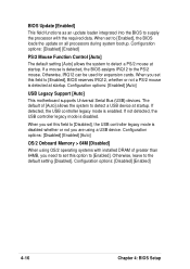
...to [Enabled]. Configuration options: [Enabled] [Auto] USB Legacy Support [Auto] This motherboard supports Universal Serial Bus (USB) devices. BIOS Update [Enabled] This field functions as an update loader integrated into the BIOS to detect a PS/2 mouse at startup. Configuration options: [Disabled] [Enabled] PS/2 Mouse Function Control [Auto] The default setting [Auto] allows the system to supply the processor with installed DRAM of [Auto] allows the system to [Disabled], the USB controller legacy mode is disabled whether or not you need to set to the default setting [Disabled].
...to [Enabled]. Configuration options: [Enabled] [Auto] USB Legacy Support [Auto] This motherboard supports Universal Serial Bus (USB) devices. BIOS Update [Enabled] This field functions as an update loader integrated into the BIOS to detect a PS/2 mouse at startup. Configuration options: [Disabled] [Enabled] PS/2 Mouse Function Control [Auto] The default setting [Auto] allows the system to supply the processor with installed DRAM of [Auto] allows the system to [Disabled], the USB controller legacy mode is disabled whether or not you need to set to the default setting [Disabled].
Motherboard DIY Troubleshooting Guide
Page 72
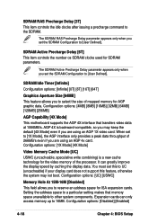
... default [4X Mode] even if you are using an AGP 1X video card. Configuration options: [1X Mode] [4X Mode] Video Memory Cache Mode [UC] USWC (uncacheable, speculative write combining) is backward-compatible, so you to [User Defined]. You must set the SDRAM Configuration to select the size of the processor. Configuration options: [Disabled] [Enabled] 4-18 Chapter 4: BIOS Setup It can only access memory up to [User Defined]. Expansion cards can greatly improve the display speed by caching the display data. When set...
... default [4X Mode] even if you are using an AGP 1X video card. Configuration options: [1X Mode] [4X Mode] Video Memory Cache Mode [UC] USWC (uncacheable, speculative write combining) is backward-compatible, so you to [User Defined]. You must set the SDRAM Configuration to select the size of the processor. Configuration options: [Disabled] [Enabled] 4-18 Chapter 4: BIOS Setup It can only access memory up to [User Defined]. Expansion cards can greatly improve the display speed by caching the display data. When set...
Motherboard DIY Troubleshooting Guide
Page 73
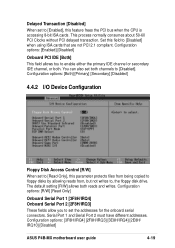
... addresses. This process normally consumes about 50-60 PCI Clocks without PCI delayed transaction. Configuration options: [3F8H/IRQ4] [2F8H/IRQ3] [3E8H/IRQ4] [2E8H/ IRQ10] [Disabled] ASUS P4B-MX motherboard user guide 4-19 Configuration options: [R/W] [Read Only] Onboard Serial Port 1 [3F8H/IRQ4] Onboard Serial Port 2 [2F8H/IRQ3] These fields allow you to enable either the primary IDE channel or secondary IDE channel, or both. Set this field to [Read Only], this feature frees the PCI bus when the CPU is accessing 8-bit ISA cards.
... addresses. This process normally consumes about 50-60 PCI Clocks without PCI delayed transaction. Configuration options: [3F8H/IRQ4] [2F8H/IRQ3] [3E8H/IRQ4] [2E8H/ IRQ10] [Disabled] ASUS P4B-MX motherboard user guide 4-19 Configuration options: [R/W] [Read Only] Onboard Serial Port 1 [3F8H/IRQ4] Onboard Serial Port 2 [2F8H/IRQ3] These fields allow you to enable either the primary IDE channel or secondary IDE channel, or both. Set this field to [Read Only], this feature frees the PCI bus when the CPU is accessing 8-bit ISA cards.
Motherboard DIY Troubleshooting Guide
Page 74
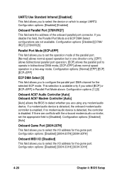
... for the game port. If you disable this field, the Parallel Port Mode and ECP DMA Select configurations are using any modem/audio device. If there are conflicts with the onboard modem/audio controller, set the operation mode of the onboard parallel port connector. Configuration options: [Disabled] [330H-331H] [300H-301H] 4-20 Chapter 4: BIOS Setup This selection is disabled. Configuration options: [Disabled] [Auto] Onboard Game Port [200H-207H] This field allows you to assign UART2. Configuration options: [Disabled] [Enabled] Onboard Parallel Port [378H/IRQ7...
... for the game port. If you disable this field, the Parallel Port Mode and ECP DMA Select configurations are using any modem/audio device. If there are conflicts with the onboard modem/audio controller, set the operation mode of the onboard parallel port connector. Configuration options: [Disabled] [330H-331H] [300H-301H] 4-20 Chapter 4: BIOS Setup This selection is disabled. Configuration options: [Disabled] [Auto] Onboard Game Port [200H-207H] This field allows you to assign UART2. Configuration options: [Disabled] [Enabled] Onboard Parallel Port [378H/IRQ7...
Motherboard DIY Troubleshooting Guide
Page 75
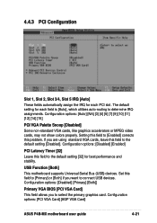
...] ASUS P4B-MX motherboard user guide 4-21 Configuration options: [Disabled] [Enabled] PCI Latency Timer [32] Leave this problem. If you are using standard VGA cards, leave this field to [Primary] or [Both] if you to select the primary graphics card. Configuration options: [Disabled] [Primary] [Both]] Primary VGA BIOS [PCI VGA Card] This field allows you want to connect USB devices. Set this field to the default setting [Disabled]. 4.4.3 PCI Configuration Slot 1, Slot 2, Slot 3/4, Slot 5 IRQ [Auto] These fields automatically assign the IRQ for each field is [Auto], which utilizes...
...] ASUS P4B-MX motherboard user guide 4-21 Configuration options: [Disabled] [Enabled] PCI Latency Timer [32] Leave this problem. If you are using standard VGA cards, leave this field to [Primary] or [Both] if you to select the primary graphics card. Configuration options: [Disabled] [Primary] [Both]] Primary VGA BIOS [PCI VGA Card] This field allows you want to connect USB devices. Set this field to the default setting [Disabled]. 4.4.3 PCI Configuration Slot 1, Slot 2, Slot 3/4, Slot 5 IRQ [Auto] These fields automatically assign the IRQ for each field is [Auto], which utilizes...
Motherboard DIY Troubleshooting Guide
Page 84
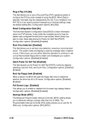
... or use a virus-free bootable floppy disk to enable or disable the full screen logo display feature. Select [Yes] if you want to determine whether the drive has 40 or 80 tracks. Configuration options: [Disabled] [Enabled] Full Screen Logo [Enabled] This allows you to restart and investigate your system. Configuration options: [Disabled] [Enabled] Interrupt Mode [APIC] The Advanced Programmable Interrupt Controller (APIC) setting allows you to configure the PCI bus slots instead of using the BIOS. Configuration options: [No] [Yes] Reset Configuration...
... or use a virus-free bootable floppy disk to enable or disable the full screen logo display feature. Select [Yes] if you want to determine whether the drive has 40 or 80 tracks. Configuration options: [Disabled] [Enabled] Full Screen Logo [Enabled] This allows you to restart and investigate your system. Configuration options: [Disabled] [Enabled] Interrupt Mode [APIC] The Advanced Programmable Interrupt Controller (APIC) setting allows you to configure the PCI bus slots instead of using the BIOS. Configuration options: [No] [Yes] Reset Configuration...
Motherboard DIY Troubleshooting Guide
Page 89
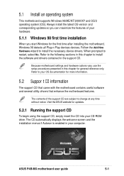
... time after installing the motherboard, Windows 98 detects all Plug-n-Play devices devices. Refer to install the software and drivers contained in your CD-ROM drive. ASUS P4B-MX motherboard user guide 5-1 Because motherboard settings and hardware options vary, use the setup procedures presented in this chapter to your OS documentation for updates. 5.2.1 Running the support CD To begin using the support CD, simply insert the CD into your computer. 5.1 Install an operating system This motherboard supports Windows 98/ME...
... time after installing the motherboard, Windows 98 detects all Plug-n-Play devices devices. Refer to install the software and drivers contained in your CD-ROM drive. ASUS P4B-MX motherboard user guide 5-1 Because motherboard settings and hardware options vary, use the setup procedures presented in this chapter to your OS documentation for updates. 5.2.1 Running the support CD To begin using the support CD, simply insert the CD into your computer. 5.1 Install an operating system This motherboard supports Windows 98/ME...
Motherboard DIY Troubleshooting Guide
Page 93
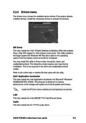
... installs the AC '97 PCI audio driver. This utility installs to the operating system how the chipset components will be configured. This is designed to activate the devices. You may install this utility in the silent and unattended preload modes. INF Driver This item installs the Intel® Chipset Software Installation Utility that enables Plug-n-Play INF support for Microsoft® Windows® 98/98SE/ME/NT4.0/2000. ASUS P4B-MX motherboard user guide 5-5 5.2.4 Drivers menu The drivers menu shows the available device drivers...
... installs the AC '97 PCI audio driver. This utility installs to the operating system how the chipset components will be configured. This is designed to activate the devices. You may install this utility in the silent and unattended preload modes. INF Driver This item installs the Intel® Chipset Software Installation Utility that enables Plug-n-Play INF support for Microsoft® Windows® 98/98SE/ME/NT4.0/2000. ASUS P4B-MX motherboard user guide 5-5 5.2.4 Drivers menu The drivers menu shows the available device drivers...
Motherboard DIY Troubleshooting Guide
Page 101
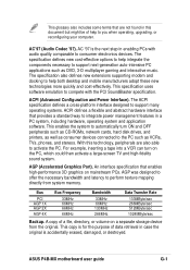
...-screen TV and high-fidelity sound system. For example, inserting a tape into a VCR can turn ON and OFF peripherals such as CD-ROMs, network cards, hard disk drives, and printers, as well as consumer devices connected to the PC such as DVD, 3-D multiplayer gaming and interactive music. A copy of help to you when operating, upgrading, or reconfiguring your computer. ASUS P4B-MX motherboard user guide G-1 ACPI (Advanced Configuration and Power Interface). The ACPI specification defines...
...-screen TV and high-fidelity sound system. For example, inserting a tape into a VCR can turn ON and OFF peripherals such as CD-ROMs, network cards, hard disk drives, and printers, as well as consumer devices connected to the PC such as DVD, 3-D multiplayer gaming and interactive music. A copy of help to you when operating, upgrading, or reconfiguring your computer. ASUS P4B-MX motherboard user guide G-1 ACPI (Advanced Configuration and Power Interface). The ACPI specification defines...


