Motherboard DIY Troubleshooting Guide
Page 4
... 2-18 2.8 Connectors 2-21 Chapter 3: Powering up 3-1 3.1 Starting up for the first time 3-1 3.3 Powering off the computer 3-2 Chapter 4: BIOS setup 4-1 4.1 Managing and updating your BIOS 4-1 4.1.1 Using the computer system for the first time 4-1 4.1.2 Updating BIOS procedures 4-3 4.2 BIOS Setup program 4-5 4.2.1 BIOS menu bar 4-6 4.2.2 Legend bar 4-6 4.3 Main menu 4-8 4.3.1 Primary & Secondary Master/Slave 4-9 4.3.2 Keyboard Features 4-13 4.4 Advanced Menu 4-15...
... 2-18 2.8 Connectors 2-21 Chapter 3: Powering up 3-1 3.1 Starting up for the first time 3-1 3.3 Powering off the computer 3-2 Chapter 4: BIOS setup 4-1 4.1 Managing and updating your BIOS 4-1 4.1.1 Using the computer system for the first time 4-1 4.1.2 Updating BIOS procedures 4-3 4.2 BIOS Setup program 4-5 4.2.1 BIOS menu bar 4-6 4.2.2 Legend bar 4-6 4.3 Main menu 4-8 4.3.1 Primary & Secondary Master/Slave 4-9 4.3.2 Keyboard Features 4-13 4.4 Advanced Menu 4-15...
Motherboard DIY Troubleshooting Guide
Page 8
...lists the technical terms that you have to change system settings through the BIOS Setup menus. It includes description of the P4B-MX motherboard. About this guide This user guide contains the information you may encounter...BIOS beep codes. • Chapter 4: BIOS setup This chapter tells how to perform when installing system components. viii It includes brief descriptions of the special attributes of the motherboard and the new technology it supports. • Chapter 2: Hardware information This chapter lists the hardware setup procedures that you need when installing the ASUS P4B-MX...
...lists the technical terms that you have to change system settings through the BIOS Setup menus. It includes description of the P4B-MX motherboard. About this guide This user guide contains the information you may encounter...BIOS beep codes. • Chapter 4: BIOS setup This chapter tells how to perform when installing system components. viii It includes brief descriptions of the special attributes of the motherboard and the new technology it supports. • Chapter 2: Hardware information This chapter lists the hardware setup procedures that you need when installing the ASUS P4B-MX...
Motherboard DIY Troubleshooting Guide
Page 15
This Low Pin Count (LPC) chipset combines the commonly used Super I /O chipset. This 2Mb firmware contains the programmable BIOS program. 9 DIP switches. The MCH along with MPU-401 UART mode. 5 ATX power connector. The power supply must have at least ...) connectors are interconnected through the Intel proprietary Hub interface. This 10-switch Dual Inline Package (DIP) allows you to an ATX 12V power supply. ASUS P4B-MX motherboard user guide 1-3 This socket accommodates the Intel® Pentium® 4 478/Northwood Processor with 400MHz system bus. 2 North bridge controller. This...
This Low Pin Count (LPC) chipset combines the commonly used Super I /O chipset. This 2Mb firmware contains the programmable BIOS program. 9 DIP switches. The MCH along with MPU-401 UART mode. 5 ATX power connector. The power supply must have at least ...) connectors are interconnected through the Intel proprietary Hub interface. This 10-switch Dual Inline Package (DIP) allows you to an ATX 12V power supply. ASUS P4B-MX motherboard user guide 1-3 This socket accommodates the Intel® Pentium® 4 478/Northwood Processor with 400MHz system bus. 2 North bridge controller. This...
Motherboard DIY Troubleshooting Guide
Page 34
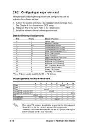
... an IRQ to the tables below. 3. PCI slot 2 - - - - - - shared - - - - - - shared - - - - - Install the software drivers for information on BIOS setup. 2. PCI slot 3 - - Onboard USB controller HC1 shared AGP shared Onboard Audio - When using PCI cards on the system and change the necessary... BIOS settings, if any. 2.6.2 Configuring an expansion card After physically installing the expansion card, configure the card by adjusting the ...
... an IRQ to the tables below. 3. PCI slot 2 - - - - - - shared - - - - - - shared - - - - - Install the software drivers for information on BIOS setup. 2. PCI slot 3 - - Onboard USB controller HC1 shared AGP shared Onboard Audio - When using PCI cards on the system and change the necessary... BIOS settings, if any. 2.6.2 Configuring an expansion card After physically installing the expansion card, configure the card by adjusting the ...
Motherboard DIY Troubleshooting Guide
Page 36
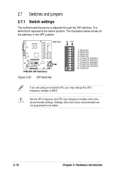
... 10. SW1801 ON OFF ON 1 2 3 4 5 6 7 8 9 10 ® P4B-MX P4B-MX DIP Switches Figure 2-20 DIP Switches 1. Reserved 3. Settings other than those recommended are using an unlocked CPU, you may change the CPU frequency multiple in the OFF position. The illustration below shows all the switches in BIOS. Frequency Selection 9. Reserved 2. Frequency Selection 6. Reserved 5. The...
... 10. SW1801 ON OFF ON 1 2 3 4 5 6 7 8 9 10 ® P4B-MX P4B-MX DIP Switches Figure 2-20 DIP Switches 1. Reserved 3. Settings other than those recommended are using an unlocked CPU, you may change the CPU frequency multiple in the OFF position. The illustration below shows all the switches in BIOS. Frequency Selection 9. Reserved 2. Frequency Selection 6. Reserved 5. The...
Motherboard DIY Troubleshooting Guide
Page 40
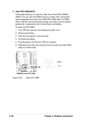
... computer and unplug the power cord. 2. Plug the power cord and turn ON the computer. 6. Hold down the key during the boot process and enter BIOS setup to clear the Real Time Clock (RTC) RAM in CMOS, that include system setup information such as system passwords, is powered by erasing the... CMOS RTC RAM data. 3. To erase the RTC RAM: 1. Clear RTC RAM (R272) These pads allow you to re-enter data. ® P4B-MX P4B-MX Clear RTC RAM Figure 2-24 Clear RTC RAM Intel I/O Controller Hub (ICH2) R272 2-20 Chapter 2: Hardware information
... computer and unplug the power cord. 2. Plug the power cord and turn ON the computer. 6. Hold down the key during the boot process and enter BIOS setup to clear the Real Time Clock (RTC) RAM in CMOS, that include system setup information such as system passwords, is powered by erasing the... CMOS RTC RAM data. 3. To erase the RTC RAM: 1. Clear RTC RAM (R272) These pads allow you to re-enter data. ® P4B-MX P4B-MX Clear RTC RAM Figure 2-24 Clear RTC RAM Intel I/O Controller Hub (ICH2) R272 2-20 Chapter 2: Hardware information

Motherboard DIY Troubleshooting Guide
Page 42
...primary IDE connector and another UltraDMA/100/66 cable. Pin 20 on the UltraDMA cable connector. Secondary IDE Connector Primary IDE Connector ® P4B-MX P4B-MX IDE Connectors Figure 2-26 IDE Connectors NOTE: Orient the red markings (usually zigzag) on the UltraDMA/100/66 cable is intentional. This ... UltraDMA/100/66 slave device (hard disk drive) and the black connector to the hard disk documentation for the secondary IDE connector. 1. BIOS supports specific device bootup. You may configure two hard disks to PIN 1. The hole near the blue connector on the IDE ribbon cable...
...primary IDE connector and another UltraDMA/100/66 cable. Pin 20 on the UltraDMA cable connector. Secondary IDE Connector Primary IDE Connector ® P4B-MX P4B-MX IDE Connectors Figure 2-26 IDE Connectors NOTE: Orient the red markings (usually zigzag) on the UltraDMA/100/66 cable is intentional. This ... UltraDMA/100/66 slave device (hard disk drive) and the black connector to the hard disk documentation for the secondary IDE connector. 1. BIOS supports specific device bootup. You may configure two hard disks to PIN 1. The hole near the blue connector on the IDE ribbon cable...

Motherboard DIY Troubleshooting Guide
Page 44
...pins as shown in the chassis. ® P4B-MX USB 1 5 6 10 1: USB Power 2: USBP2- 3: USBP2+ 4: GND 5: NC 6: USB Power 7: USBP3- 8: USBP3+ 9: GND P4B-MX USB Header Figure 2-29 USB Header 6. This module mounts to the pin definitions.. IR 1 ® P4B-MX P4B-MX Infrared Module Connector Figure 2-30 Infrared Module ...Connector +5V (NC) IRRX GND IRTX Front View Back View IRTX +5V GND (NC) IRRX 2-24 Chapter 2: Hardware information You must also configure the UART2 Use As parameter in BIOS to set to ...
...pins as shown in the chassis. ® P4B-MX USB 1 5 6 10 1: USB Power 2: USBP2- 3: USBP2+ 4: GND 5: NC 6: USB Power 7: USBP3- 8: USBP3+ 9: GND P4B-MX USB Header Figure 2-29 USB Header 6. This module mounts to the pin definitions.. IR 1 ® P4B-MX P4B-MX Infrared Module Connector Figure 2-30 Infrared Module ...Connector +5V (NC) IRRX GND IRTX Front View Back View IRTX +5V GND (NC) IRRX 2-24 Chapter 2: Hardware information You must also configure the UART2 Use As parameter in BIOS to set to ...
Motherboard DIY Troubleshooting Guide
Page 48
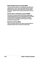
... system power. 2-28 Chapter 2: Hardware information Pressing the power switch turns the system between ON and SLEEP, or ON and SOFT OFF, depending on the BIOS or OS settings. Attach the case-mounted suspend switch to the case-mounted reset switch for more than 4 seconds turns the system OFF. • Reset...
... system power. 2-28 Chapter 2: Hardware information Pressing the power switch turns the system between ON and SLEEP, or ON and SOFT OFF, depending on the BIOS or OS settings. Attach the case-mounted suspend switch to the case-mounted reset switch for more than 4 seconds turns the system OFF. • Reset...

Motherboard DIY Troubleshooting Guide
Page 49
Chapter 3 This chapter describes the power up Powering up sequence and gives information on the BIOS beep codes.
Chapter 3 This chapter describes the power up Powering up sequence and gives information on the BIOS beep codes.

Motherboard DIY Troubleshooting Guide
Page 51
... beep followed by three short beeps High frequency beeps when system is equipped with a surge protector. 5. Connect the power cord to enter BIOS Setup. If you do not see anything within 30 seconds from the time you turned on the power, the system may light up .... when displaying logo Long beeps in Chapter 4. If your retailer for the first time 1. Monitor b. System running , the BIOS beeps or additional messages appear on the chain) c. ASUS P4B-MX motherboard user guide 3-1 After making all switches are using an ATX power supply, you are off. 3. Be sure that ...
... beep followed by three short beeps High frequency beeps when system is equipped with a surge protector. 5. Connect the power cord to enter BIOS Setup. If you do not see anything within 30 seconds from the time you turned on the power, the system may light up .... when displaying logo Long beeps in Chapter 4. If your retailer for the first time 1. Monitor b. System running , the BIOS beeps or additional messages appear on the chain) c. ASUS P4B-MX motherboard user guide 3-1 After making all switches are using an ATX power supply, you are off. 3. Be sure that ...
Motherboard DIY Troubleshooting Guide
Page 53
Detailed descriptions of the BIOS parameters are also provided. Chapter 4 This chapter tells how to change system settings through the BIOS Setup menus. BIOS setup
Detailed descriptions of the BIOS parameters are also provided. Chapter 4 This chapter tells how to change system settings through the BIOS Setup menus. BIOS setup
Motherboard DIY Troubleshooting Guide
Page 55
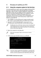
...boot disk you created. Type COPY D:\AFLASH\AFLASH.EXE A:\ (assuming D is not supported by the ACPI BIOS and therefore, cannot be loaded when you boot from the floppy disk. ASUS P4B-MX motherboard user guide 4-1 AFLASH.EXE is a Flash Memory Writer utility that you save a copy of your ...screen during bootup. DO NOT copy AUTOEXEC.BAT and CONFIG.SYS to the disk. 2. 4.1 Managing and updating your BIOS 4.1.1 Using the computer system for...
...boot disk you created. Type COPY D:\AFLASH\AFLASH.EXE A:\ (assuming D is not supported by the ACPI BIOS and therefore, cannot be loaded when you boot from the floppy disk. ASUS P4B-MX motherboard user guide 4-1 AFLASH.EXE is a Flash Memory Writer utility that you save a copy of your ...screen during bootup. DO NOT copy AUTOEXEC.BAT and CONFIG.SYS to the disk. 2. 4.1 Managing and updating your BIOS 4.1.1 Using the computer system for...
Motherboard DIY Troubleshooting Guide
Page 56
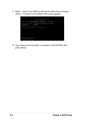
Type a filename and the path, for example, A:\XXX-XX.XXX, then press . 4-2 Chapter 4: BIOS Setup Select 1. Save Current BIOS to File from the Main menu and press . The Save Current BIOS To File screen appears. 6. 5.
Type a filename and the path, for example, A:\XXX-XX.XXX, then press . 4-2 Chapter 4: BIOS Setup Select 1. Save Current BIOS to File from the Main menu and press . The Save Current BIOS To File screen appears. 6. 5.
Motherboard DIY Troubleshooting Guide
Page 57
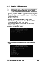
...then press . 4. The Update BIOS Including Boot Block and ESCD screen appears. 5. When prompted to confirm the BIOS update, press Y to more problems with the motherboard! 1. To cancel this operation, press . 6. ASUS P4B-MX motherboard user guide 4-3 Download an updated ASUS BIOS file from the floppy disk.... 3. At the Main Menu, type 2 then press . Boot from the Internet (see the ASUS Contact Information on page x for details) and save...
...then press . 4. The Update BIOS Including Boot Block and ESCD screen appears. 5. When prompted to confirm the BIOS update, press Y to more problems with the motherboard! 1. To cancel this operation, press . 6. ASUS P4B-MX motherboard user guide 4-3 Download an updated ASUS BIOS file from the floppy disk.... 3. At the Main Menu, type 2 then press . Boot from the Internet (see the ASUS Contact Information on page x for details) and save...

Motherboard DIY Troubleshooting Guide
Page 58
... the process, and if the problem persists, load the original BIOS file you encounter problems while updating the new BIOS, DO NOT turn off the system because this happens, call the ASUS service center for support. 4-4 Chapter 4: BIOS Setup If this may not boot. Follow the onscreen instructions to... program the new BIOS information into the Flash ROM. If you ...
... the process, and if the problem persists, load the original BIOS file you encounter problems while updating the new BIOS, DO NOT turn off the system because this happens, call the ASUS service center for support. 4-4 Chapter 4: BIOS Setup If this may not boot. Follow the onscreen instructions to... program the new BIOS information into the Flash ROM. If you ...
Motherboard DIY Troubleshooting Guide
Page 59
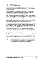
...the Setup program, you with its test routines. Even if you are installing a motherboard, reconfiguring your BIOS." It is designed to make it as easy to "Run Setup". Use the BIOS Setup program when you are not prompted to use as possible. This section explains how to run ... chassis. Do this last option only if the first two failed. ASUS P4B-MX motherboard user guide 4-5 For example, you to enter the Setup utility, otherwise, POST continues with the opportunity to configure your system using the BIOS Setup program so that you wish to enter Setup after POST, restart...
...the Setup program, you with its test routines. Even if you are installing a motherboard, reconfiguring your BIOS." It is designed to make it as easy to "Run Setup". Use the BIOS Setup program when you are not prompted to use as possible. This section explains how to run ... chassis. Do this last option only if the first two failed. ASUS P4B-MX motherboard user guide 4-5 For example, you to enter the Setup utility, otherwise, POST continues with the opportunity to configure your system using the BIOS Setup program so that you wish to enter Setup after POST, restart...

Motherboard DIY Troubleshooting Guide
Page 60
...last field Resets the current screen to its Setup Defaults Saves changes and exits Setup 4-6 Chapter 4: BIOS Setup To access the menu bar items, press the right or left or right Up or Down arrow...and make changes to exit the Setup program. The following table lists the keys found in the BIOS Setup Jumps to the Exit menu or returns to the main menu from a sub-menu Left or... Right arrow Selects the menu item to the advanced features. 4.2.1 BIOS menu bar The top of the Setup screen is highlighted. 4.2.2 Legend bar At the bottom of the ...
...last field Resets the current screen to its Setup Defaults Saves changes and exits Setup 4-6 Chapter 4: BIOS Setup To access the menu bar items, press the right or left or right Up or Down arrow...and make changes to exit the Setup program. The following table lists the keys found in the BIOS Setup Jumps to the Exit menu or returns to the main menu from a sub-menu Left or... Right arrow Selects the menu item to the advanced features. 4.2.1 BIOS menu bar The top of the Setup screen is highlighted. 4.2.2 Legend bar At the bottom of the ...
Motherboard DIY Troubleshooting Guide
Page 61
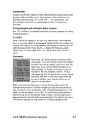
...program. Use the legend keys to enter values and move the highlight to load the Setup default values. If you would within a menu. ASUS P4B-MX motherboard user guide 4-7 The General Help screen lists the legend keys and their corresponding functions. Press to display the first page, press to ...go to the main menu. To display a sub-menu, move from any of a help In addition to the Item Specific Help window, the BIOS setup program also provides a General Help screen. While moving around through the entire help window, press or . Saving changes and exiting the Setup program...
...program. Use the legend keys to enter values and move the highlight to load the Setup default values. If you would within a menu. ASUS P4B-MX motherboard user guide 4-7 The General Help screen lists the legend keys and their corresponding functions. Press to display the first page, press to ...go to the main menu. To display a sub-menu, move from any of a help In addition to the Item Specific Help window, the BIOS setup program also provides a General Help screen. While moving around through the entire help window, press or . Saving changes and exiting the Setup program...
Motherboard DIY Troubleshooting Guide
Page 62
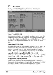
... values for hour, minute and second are Month: (1 to 12), Day: (1 to 31), Year: (up to 1.44MB) on a 3.5-inch diskette. Configuration options: [Disabled] [Enabled] 4-8 Chapter 4: BIOS Setup
... values for hour, minute and second are Month: (1 to 12), Day: (1 to 31), Year: (up to 1.44MB) on a 3.5-inch diskette. Configuration options: [Disabled] [Enabled] 4-8 Chapter 4: BIOS Setup


