P3V133 User Manual
Page 4
FEATURES 8 2.1 The ASUS P3V133 8 2.1.1 Specifications 8 2.1.2 Special Features 10 2.1.3 Performance Features 10 2.1.4 Intelligence 11 2.2 P3V133 Motherboard Components 12 3. INTRODUCTION 7 1.1 How This Manual Is Organized 7 1.2 Item Checklist 7 2. CONTENTS 1. HARDWARE SETUP 14 3.1 P3V133 Motherboard Layout 14 3.2 Layout Contents 15 3.3 Hardware Setup Steps 16 3.4 Motherboard Settings 16 3.5 System Memory (DIMM 20 3.6 Central Processing Unit (CPU 23 3.6.1 Quick CPU Installation Procedure...
FEATURES 8 2.1 The ASUS P3V133 8 2.1.1 Specifications 8 2.1.2 Special Features 10 2.1.3 Performance Features 10 2.1.4 Intelligence 11 2.2 P3V133 Motherboard Components 12 3. INTRODUCTION 7 1.1 How This Manual Is Organized 7 1.2 Item Checklist 7 2. CONTENTS 1. HARDWARE SETUP 14 3.1 P3V133 Motherboard Layout 14 3.2 Layout Contents 15 3.3 Hardware Setup Steps 16 3.4 Motherboard Settings 16 3.5 System Memory (DIMM 20 3.6 Central Processing Unit (CPU 23 3.6.1 Quick CPU Installation Procedure...
P3V133 User Manual
Page 5
... 7.2.2 Software Driver Support 90 7.2.3 Questions and Answers 90 7.3 Glossary 91 ASUS P3V133 User's Manual 5 SOFTWARE SETUP 73 5.1 Operating Systems 73 5.1.1 Windows 98 First Time Installation 73 5.2 P3V Series Motherboard Support CD 74 5.3 ASUS PC Probe Setup 75 5.4 Adobe Acrobat Reader 76 5.5 Install VIA 4 in 1 Driver 77 5.6 Install PC-Cillin 78 5.7 Uninstalling Programs 79 6. SOFTWARE REFERENCE 81...
... 7.2.2 Software Driver Support 90 7.2.3 Questions and Answers 90 7.3 Glossary 91 ASUS P3V133 User's Manual 5 SOFTWARE SETUP 73 5.1 Operating Systems 73 5.1.1 Windows 98 First Time Installation 73 5.2 P3V Series Motherboard Support CD 74 5.3 ASUS PC Probe Setup 75 5.4 Adobe Acrobat Reader 76 5.5 Install VIA 4 in 1 Driver 77 5.6 Install PC-Cillin 78 5.7 Uninstalling Programs 79 6. SOFTWARE REFERENCE 81...
P3V133 User Manual
Page 6
...DC: Office of Communications. This Class B digital apparatus complies with the limits for radio noise emissions from digital apparatus set out in a residential installation. However, there is subject to the following measures: • Re-orient or relocate the receiving antenna. • Increase the separation between ...TV technician for help. Cet appareil numérique de la classe B est conforme à la norme NMB-003 du Canada. 6 ASUS P3V133 User's Manual If this product not expressly approved by one or more of the following two conditions: • This device may not ...
...DC: Office of Communications. This Class B digital apparatus complies with the limits for radio noise emissions from digital apparatus set out in a residential installation. However, there is subject to the following measures: • Re-orient or relocate the receiving antenna. • Increase the separation between ...TV technician for help. Cet appareil numérique de la classe B est conforme à la norme NMB-003 du Canada. 6 ASUS P3V133 User's Manual If this product not expressly approved by one or more of the following two conditions: • This device may not ...
P3V133 User Manual
Page 10
... transfers using PC133-compliant SDRAM. 10 ASUS P3V133 User's Manual This motherboard with existing DMA devices and systems so there is no need to upgrade current EIDE/IDE drives and host systems. (UltraDMA/66 requires a 40-pin 80-conductor cable to be used. • Easy Installation: Incorporates BIOS that support OS Direct Power...
... transfers using PC133-compliant SDRAM. 10 ASUS P3V133 User's Manual This motherboard with existing DMA devices and systems so there is no need to upgrade current EIDE/IDE drives and host systems. (UltraDMA/66 requires a 40-pin 80-conductor cable to be used. • Easy Installation: Incorporates BIOS that support OS Direct Power...
P3V133 User Manual
Page 16
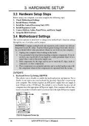
...follow some precautions whenever you must complete the following steps: 1. KBPWR 3 2 1 Disable (Default) 3 2 1 Enable P3V133 R P3V133 Keyboard Power Up 16 ASUS P3V133 User's Manual Setup the BIOS Software 3.4 Motherboard Settings This section explains in detail how to change your motherboard's function settings ...use of your keyboard (by the edges and try not to a metal object, such as the power supply case. 3. Install Memory Modules 3. Install the Central Processing Unit (CPU) 4. Jumpers 1. Unplug your computer. 1. HARDWARE SETUP 3.3 Hardware Setup Steps Before using your...
...follow some precautions whenever you must complete the following steps: 1. KBPWR 3 2 1 Disable (Default) 3 2 1 Enable P3V133 R P3V133 Keyboard Power Up 16 ASUS P3V133 User's Manual Setup the BIOS Software 3.4 Motherboard Settings This section explains in detail how to change your motherboard's function settings ...use of your keyboard (by the edges and try not to a metal object, such as the power supply case. 3. Install Memory Modules 3. Install the Central Processing Unit (CPU) 4. Jumpers 1. Unplug your computer. 1. HARDWARE SETUP 3.3 Hardware Setup Steps Before using your...
P3V133 User Manual
Page 20
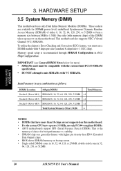
... is the memory of choice for best performance vs. stability. • SDRAM chips are generally thinner with VC SDRAMs. Install memory in 32, 64, 128, 256, or 512MB. 20 ASUS P3V133 User's Manual double-sided come in any combination as follows: DIMM Location Socket 1 (Rows 0&1) Socket 2 (Rows 2&3)... Total Memory x1 x1 x1 = NOTES • DIMMs that have more ) • SDRAMs used must use only PC100-compliant DIMMs. • ASUS motherboards support SPD (Serial Presence Detect) DIMMs. This is recommended through SDRAM Configuration in 16, 32, 64, 128, or 256MB; HARDWARE SETUP 3.5 ...
... is the memory of choice for best performance vs. stability. • SDRAM chips are generally thinner with VC SDRAMs. Install memory in 32, 64, 128, 256, or 512MB. 20 ASUS P3V133 User's Manual double-sided come in any combination as follows: DIMM Location Socket 1 (Rows 0&1) Socket 2 (Rows 2&3)... Total Memory x1 x1 x1 = NOTES • DIMMs that have more ) • SDRAMs used must use only PC100-compliant DIMMs. • ASUS motherboards support SPD (Serial Presence Detect) DIMMs. This is recommended through SDRAM Configuration in 16, 32, 64, 128, or 256MB; HARDWARE SETUP 3.5 ...
P3V133 User Manual
Page 21
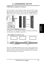
...-Pin DIMM Memory Sockets The DIMMs must tell your retailer the correct DIMM type before purchasing. ASUS P3V133 User's Manual 21 H/W SETUP System Memory 3. DRAM SIMM modules have a higher pin density. You must be 3.3Volt unbuffered SDRAMs. To determine the DIMM type, ...to identify the type and also to prevent the wrong type from being inserted into the DIMM slot on the motherboard. HARDWARE SETUP DIMM Memory Installation Procedures: Insert the module(s) as shown. This motherboard supports four clock signals. SDRAM DIMMs have different pin contacts on each side and therefore have...
...-Pin DIMM Memory Sockets The DIMMs must tell your retailer the correct DIMM type before purchasing. ASUS P3V133 User's Manual 21 H/W SETUP System Memory 3. DRAM SIMM modules have a higher pin density. You must be 3.3Volt unbuffered SDRAMs. To determine the DIMM type, ...to identify the type and also to prevent the wrong type from being inserted into the DIMM slot on the motherboard. HARDWARE SETUP DIMM Memory Installation Procedures: Insert the module(s) as shown. This motherboard supports four clock signals. SDRAM DIMMs have different pin contacts on each side and therefore have...
P3V133 User Manual
Page 23
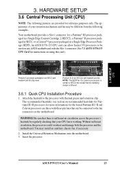
...connected to the fan connectors on using this card). 3. ASUS P3V133 User's Manual 23 3. An ASUS S370-133 CPU card can be used on any ASUS motherboard with three-pin fans that your retention mechanism and fan may install an auxiliary chassis fan, if necessary. 2. You may be... different from the following pictures are those with the Slot 1 connector (See 7.1 ASUS S370-133 CPU Card for reference purposes only. Insert the processor....
...connected to the fan connectors on using this card). 3. ASUS P3V133 User's Manual 23 3. An ASUS S370-133 CPU card can be used on any ASUS motherboard with three-pin fans that your retention mechanism and fan may install an auxiliary chassis fan, if necessary. 2. You may be... different from the following pictures are those with the Slot 1 connector (See 7.1 ASUS S370-133 CPU Card for reference purposes only. Insert the processor....

P3V133 User Manual
Page 24
... the heatsink onto the processor and the other direction to provide adequate circulation across the processor's passive heatsink. 24 ASUS P3V133 User's Manual The following steps are provided only as a general guide and may install an auxiliary fan to release. Lock Arm Lock Arm Using SECC2 fan with a good quality thermal interface material...
... the heatsink onto the processor and the other direction to provide adequate circulation across the processor's passive heatsink. 24 ASUS P3V133 User's Manual The following steps are provided only as a general guide and may install an auxiliary fan to release. Lock Arm Lock Arm Using SECC2 fan with a good quality thermal interface material...
P3V133 User Manual
Page 25
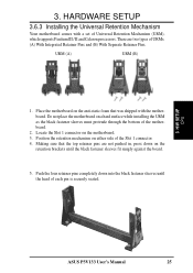
...Do not place the motherboard on either side of each pin is securely seated. 3. H/W SETUP CPU ASUS P3V133 User's Manual 25 Position the retention mechanism on a hard surface while installing the URM as the black fastener sleeves must protrude through the bottom of URMs: (A) With Integrated Retainer...retention brackets until the head of the Slot 1 connector. 4. Place the motherboard on the motherboard. 3. HARDWARE SETUP 3.6.3 Installing the Universal Retention Mechanism Your motherboard comes with the motherboard. Locate the Slot 1 connector on the anti-static foam that the...
...Do not place the motherboard on either side of each pin is securely seated. 3. H/W SETUP CPU ASUS P3V133 User's Manual 25 Position the retention mechanism on a hard surface while installing the URM as the black fastener sleeves must protrude through the bottom of URMs: (A) With Integrated Retainer...retention brackets until the head of the Slot 1 connector. 4. Place the motherboard on the motherboard. 3. HARDWARE SETUP 3.6.3 Installing the Universal Retention Mechanism Your motherboard comes with the motherboard. Locate the Slot 1 connector on the anti-static foam that the...
P3V133 User Manual
Page 26
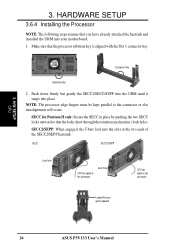
...: The processor edge fingers must be kept parallel to fan connector Locked Position (push upward) 26 ASUS P3V133 User's Manual 3. HARDWARE SETUP 3.6.4 Installing the Processor NOTE: The following steps assume that you have already attached the heatsink and installed the URM into place. SECC2/SEPP: When engaged, the T-bars lock into the slots at...
...: The processor edge fingers must be kept parallel to fan connector Locked Position (push upward) 26 ASUS P3V133 User's Manual 3. HARDWARE SETUP 3.6.4 Installing the Processor NOTE: The following steps assume that you have already attached the heatsink and installed the URM into place. SECC2/SEPP: When engaged, the T-bars lock into the slots at...
P3V133 User Manual
Page 28
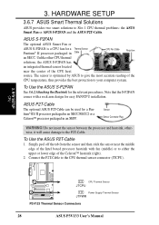
...easy FAN/CPU installation. Do not insert the sensor between the processor and heatsink, otherwise, it will cause damage to Slot 1 CPU thermal problems: the ASUS Smart Fan or ASUS S-P2FAN and the ASUS P2T-Cable. HARDWARE SETUP 3.6.7 ASUS Smart Thermal Solutions ASUS provides two smart... CPU CPU Thermal Sensor JTCPU P3V133 R Power Supply Thermal Sensor JTPWR P3V133 Thermal Sensor Connectors 28 ASUS P3V133 User's Manual ASUS S-P2FAN The optional ASUS Smart Fan or ASUS S-P2FAN is optimized by ASUS to your computer system. ASUS P2T-Cable The optional ASUS P2T-Cable can be used ...
...easy FAN/CPU installation. Do not insert the sensor between the processor and heatsink, otherwise, it will cause damage to Slot 1 CPU thermal problems: the ASUS Smart Fan or ASUS S-P2FAN and the ASUS P2T-Cable. HARDWARE SETUP 3.6.7 ASUS Smart Thermal Solutions ASUS provides two smart... CPU CPU Thermal Sensor JTCPU P3V133 R Power Supply Thermal Sensor JTPWR P3V133 Thermal Sensor Connectors 28 ASUS P3V133 User's Manual ASUS S-P2FAN The optional ASUS Smart Fan or ASUS S-P2FAN is optimized by ASUS to your computer system. ASUS P2T-Cable The optional ASUS P2T-Cable can be used ...

P3V133 User Manual
Page 29
...maximum specified operating temperature will shorten the processor lifetime and may be continuous with a strong retention clip. 4. H/W SETUP CPU ASUS P3V133 User's Manual 29 Therefore, the CPU temperature reported may cause unreliable operation. There is connected to the internal thermal diode. ...not a cause for system thermal management. To prevent system overheat and/or damage, it is used . 2. This is correctly installed onto the processor with no visible gap between the processor die and heatsink. HARDWARE SETUP 3.6.8 Precautions Operating a processor at temperatures...
...maximum specified operating temperature will shorten the processor lifetime and may be continuous with a strong retention clip. 4. H/W SETUP CPU ASUS P3V133 User's Manual 29 Therefore, the CPU temperature reported may cause unreliable operation. There is connected to the internal thermal diode. ...not a cause for system thermal management. To prevent system overheat and/or damage, it is used . 2. This is correctly installed onto the processor with no visible gap between the processor die and heatsink. HARDWARE SETUP 3.6.8 Precautions Operating a processor at temperatures...
P3V133 User Manual
Page 30
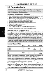
.... Replace the computer system's cover. 6. In a standard design, there are already in My Computer, contains a System icon, which gives 30 ASUS P3V133 User's Manual shared ---- Secure the card on the ISA bus. shared ------- System IRQs are available to one use , leaving 6 IRQs free ...in the ISA expansion bus first, then any available slot on the slot with the screw you intend to cards installed in 4.4.3 PCI Configuration ) 7. Expansion Card Installation Procedure 1. Read the documentation for your expansion card, such as jumpers. 2. Set up the BIOS if necessary ...
.... Replace the computer system's cover. 6. In a standard design, there are already in My Computer, contains a System icon, which gives 30 ASUS P3V133 User's Manual shared ---- Secure the card on the ISA bus. shared ------- System IRQs are available to one use , leaving 6 IRQs free ...in the ISA expansion bus first, then any available slot on the slot with the screw you intend to cards installed in 4.4.3 PCI Configuration ) 7. Expansion Card Installation Procedure 1. Read the documentation for your expansion card, such as jumpers. 2. Set up the BIOS if necessary ...
P3V133 User Manual
Page 31
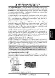
...IRQ assignment process described earlier. Since all the interrupts and addresses for ISA Cards Some ISA cards, both legacy and PNP ISA cards installed, IRQs are in the PCI and PNP configuration section of the BIOS setup utility can contact your system. Accelerated Graphics Port (AGP...AGP) slot to PNP cards from those IRQs and DMAs you the Resources tab which shows the Interrupt number and address. P3V133 R P3V133 Accelerated Graphics Port (AGP) ASUS P3V133 User's Manual 31 Make sure that do not work with the Plug and Play (PNP) specification which IRQs are handled...
...IRQ assignment process described earlier. Since all the interrupts and addresses for ISA Cards Some ISA cards, both legacy and PNP ISA cards installed, IRQs are in the PCI and PNP configuration section of the BIOS setup utility can contact your system. Accelerated Graphics Port (AGP...AGP) slot to PNP cards from those IRQs and DMAs you the Resources tab which shows the Interrupt number and address. P3V133 R P3V133 Accelerated Graphics Port (AGP) ASUS P3V133 User's Manual 31 Make sure that do not work with the Plug and Play (PNP) specification which IRQs are handled...
P3V133 User Manual
Page 34
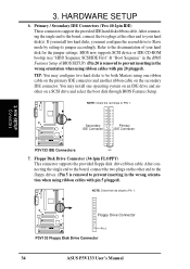
...P3V133 R Pin 1 P3V133 Floppy Disk Drive Connector 34 ASUS P3V133 User's Manual Floppy Disk Drive Connector (34-1pin FLOPPY) This connector supports the provided floppy disk drive ribbon cable. Primary / Secondary IDE Connectors (Two 40-1pin IDE) These connectors support the provided IDE hard disk ribbon cable. If you install... 20 is removed to prevent inserting in the wrong orientation when using ribbon cables with pin 5 plugged). TIP: You may install one ribbon cable on the primary IDE connector and another on a SCSI drive and select the boot disk through BIOS Features Setup...
...P3V133 R Pin 1 P3V133 Floppy Disk Drive Connector 34 ASUS P3V133 User's Manual Floppy Disk Drive Connector (34-1pin FLOPPY) This connector supports the provided floppy disk drive ribbon cable. Primary / Secondary IDE Connectors (Two 40-1pin IDE) These connectors support the provided IDE hard disk ribbon cable. If you install... 20 is removed to prevent inserting in the wrong orientation when using ribbon cables with pin 5 plugged). TIP: You may install one ribbon cable on the primary IDE connector and another on a SCSI drive and select the boot disk through BIOS Features Setup...
P3V133 User Manual
Page 39
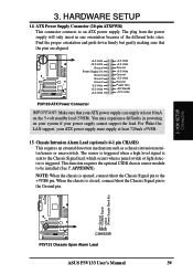
...) This connector connects to be installed (See 7. Find the proper orientation and push down firmly but gently making sure that your power supply cannot support the load. H/W SETUP Connectors P3V133 R CHASSIS P3V133 Chassis Open Alarm Lead ASUS P3V133 User's Manual 39 The plug from... the power supply will only insert in powering on the 5-volt standby lead (5VSB). P3V133 R +3.3 Volts -12.0 Volts Ground Power Supply ...
...) This connector connects to be installed (See 7. Find the proper orientation and push down firmly but gently making sure that your power supply cannot support the load. H/W SETUP Connectors P3V133 R CHASSIS P3V133 Chassis Open Alarm Lead ASUS P3V133 User's Manual 39 The plug from... the power supply will only insert in powering on the 5-volt standby lead (5VSB). P3V133 R +3.3 Volts -12.0 Volts Ground Power Supply ...
P3V133 User Manual
Page 41
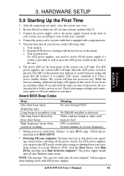
...30 seconds from the time you need to switch ON the power supply if a switch is working Meaning No error during POST No DRAM installed or detected Video card not found or video card memory bad CPU overheated System running , additional messages will appear on the front of ...on test. The system will not appear when shutting down your system user's manual. 4. The power supply should turn off the power switch. ASUS P3V133 User's Manual 41 Check your jumper settings and connections again or call your operating system before switching off your computer" will then run power-on...
...30 seconds from the time you need to switch ON the power supply if a switch is working Meaning No error during POST No DRAM installed or detected Video card not found or video card memory bad CPU overheated System running , additional messages will appear on the front of ...on test. The system will not appear when shutting down your system user's manual. 4. The power supply should turn off the power switch. ASUS P3V133 User's Manual 41 Check your jumper settings and connections again or call your operating system before switching off your computer" will then run power-on...
P3V133 User Manual
Page 45
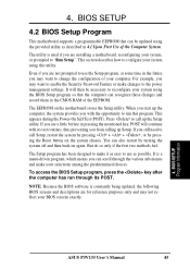
... motherboard supports a programmable EEPROM that the computer can scroll through its test routines, thus preventing you start up the Setup utility. BIOS SETUP Program Information ASUS P3V133 User's Manual 45 If you are installing a motherboard, reconfiguring your BIOS screens exactly. 4.
... motherboard supports a programmable EEPROM that the computer can scroll through its test routines, thus preventing you start up the Setup utility. BIOS SETUP Program Information ASUS P3V133 User's Manual 45 If you are installing a motherboard, reconfiguring your BIOS screens exactly. 4.
P3V133 User Manual
Page 48
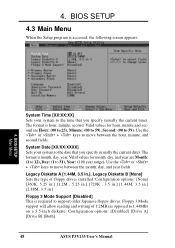
.... System Date [XX/XX/XXXX] Sets your system to the date that you specify (usually the current date). Configuration options: [Disabled] [Drive A] [Drive B] [Both] 48 ASUS P3V133 User's Manual Valid values for month, day, and year are Hour: (00 to 23), Minute: (00 to 59), Second: (00 to 31), Year: (100 year... 59). Use the or + keys to move between the month, day, and year fields. Floppy 3 Mode support will allow reading and writing of floppy drives installed. 4. Use the or + keys to move between the hour, minute, and second fields.
.... System Date [XX/XX/XXXX] Sets your system to the date that you specify (usually the current date). Configuration options: [Disabled] [Drive A] [Drive B] [Both] 48 ASUS P3V133 User's Manual Valid values for month, day, and year are Hour: (00 to 23), Minute: (00 to 59), Second: (00 to 31), Year: (100 year... 59). Use the or + keys to move between the month, day, and year fields. Floppy 3 Mode support will allow reading and writing of floppy drives installed. 4. Use the or + keys to move between the hour, minute, and second fields.


