P3V133 User Manual
Page 2
.... or (2) the serial number of the means indicated on the product itself. All Rights Reserved. For previous or updated manuals, BIOS, drivers, or product release information, contact ASUS at http://www.asus.com.tw or through any means, except documentation kept by the digit before and after the period of ASUSTeK COMPUTER INC...Microsoft Corporation. • Adobe and Acrobat are registered trademarks of Adobe Systems Incorporated. • Trend and ChipAwayVirus are trademarks of Trend Micro, Inc. Product Name: ASUS P3V133 Manual Revision: 1.02 E507 Release Date: February 2000...
.... or (2) the serial number of the means indicated on the product itself. All Rights Reserved. For previous or updated manuals, BIOS, drivers, or product release information, contact ASUS at http://www.asus.com.tw or through any means, except documentation kept by the digit before and after the period of ASUSTeK COMPUTER INC...Microsoft Corporation. • Adobe and Acrobat are registered trademarks of Adobe Systems Incorporated. • Trend and ChipAwayVirus are trademarks of Trend Micro, Inc. Product Name: ASUS P3V133 Manual Revision: 1.02 E507 Release Date: February 2000...
P3V133 User Manual
Page 4
... 4.1.1 Upon First Use of the Computer System 42 4.1.2 Updating BIOS Procedures (only when necessary) ......... 43 4.2 BIOS Setup Program 45 4.2.1 BIOS Menu Bar 46 4.2.2 Legend Bar 46 4 ASUS P3V133 User's Manual HARDWARE SETUP 14 3.1 P3V133 Motherboard Layout 14 3.2 Layout Contents 15 3.3 Hardware Setup Steps 16 3.4 Motherboard Settings 16 3.5 System Memory (DIMM 20 3.6 Central Processing Unit (CPU 23...
... 4.1.1 Upon First Use of the Computer System 42 4.1.2 Updating BIOS Procedures (only when necessary) ......... 43 4.2 BIOS Setup Program 45 4.2.1 BIOS Menu Bar 46 4.2.2 Legend Bar 46 4 ASUS P3V133 User's Manual HARDWARE SETUP 14 3.1 P3V133 Motherboard Layout 14 3.2 Layout Contents 15 3.3 Hardware Setup Steps 16 3.4 Motherboard Settings 16 3.5 System Memory (DIMM 20 3.6 Central Processing Unit (CPU 23...
P3V133 User Manual
Page 7
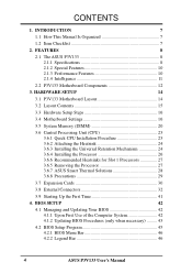
...Manual information and checklist Production information and specifications Instructions on setting up the motherboard. 1. INTRODUCTION 2. BIOS SETUP 5. Instructions on setting up the BIOS Instructions on setting up the included software Reference material for the included software Optional items and general ... with drivers and utilities (1) This Motherboard User's Manual ASUS IrDA-compliant infrared module (optional) ASUS S370 Series CPU cards (optional) ASUS PCI-L101 Wake-On-LAN 10/100 Ethernet Card (optional) ASUS P3V133 User's Manual 7 INTRODUCTION 1.1 How This Manual Is ...
...Manual information and checklist Production information and specifications Instructions on setting up the motherboard. 1. INTRODUCTION 2. BIOS SETUP 5. Instructions on setting up the BIOS Instructions on setting up the included software Reference material for the included software Optional items and general ... with drivers and utilities (1) This Motherboard User's Manual ASUS IrDA-compliant infrared module (optional) ASUS S370 Series CPU cards (optional) ASUS PCI-L101 Wake-On-LAN 10/100 Ethernet Card (optional) ASUS P3V133 User's Manual 7 INTRODUCTION 1.1 How This Manual Is ...
P3V133 User Manual
Page 9
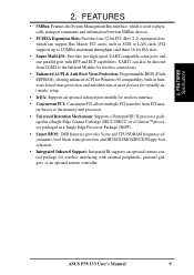
.... • Enhanced ACPI & Anti-Boot Virus Protection: Programmable BIOS (Flash EEPROM), offering enhanced ACPI for Windows 98 compatibility, built-in a Single Edge Processor Package (SEPP). • Smart BIOS: 2MB firmware provides Vcore and CPU/SDRAM frequency adjustments, boot block... write protection, and HD/SCSI/MO/ZIP/CD/Floppy boot selection. • Integrated Infrared Support: Integrated IR supports an optional remote control package for wireless interfacing with EPP and ECP capabilities. ASUS P3V133...
.... • Enhanced ACPI & Anti-Boot Virus Protection: Programmable BIOS (Flash EEPROM), offering enhanced ACPI for Windows 98 compatibility, built-in a Single Edge Processor Package (SEPP). • Smart BIOS: 2MB firmware provides Vcore and CPU/SDRAM frequency adjustments, boot block... write protection, and HD/SCSI/MO/ZIP/CD/Floppy boot selection. • Integrated Infrared Support: Integrated IR supports an optional remote control package for wireless interfacing with EPP and ECP capabilities. ASUS P3V133...
P3V133 User Manual
Page 10
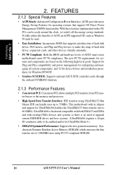
... . • Symbios SCSI BIOS: Supports optional ASUS SCSI controller cards through the onboard SYMBIOS firmware. 2.1.3 Performance Features • Concurrent PCI: Concurrent PCI allows multiple PCI transfers from PCI master busses to the memory and processor. • High-Speed Data Transfer Interface: IDE transfers using PC133-compliant SDRAM. 10 ASUS P3V133 User's Manual FEATURES 2.1.2 Special...
... . • Symbios SCSI BIOS: Supports optional ASUS SCSI controller cards through the onboard SYMBIOS firmware. 2.1.3 Performance Features • Concurrent PCI: Concurrent PCI allows multiple PCI transfers from PCI master busses to the memory and processor. • High-Speed Data Transfer Interface: IDE transfers using PC133-compliant SDRAM. 10 ASUS P3V133 User's Manual FEATURES 2.1.2 Special...
P3V133 User Manual
Page 11
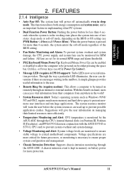
...less than 4 seconds, the system enters the soft-off mode regardless of two states: sleep mode or soft-off automatically even in sleep mode. ASUS P3V133 User's Manual 11 When the power button is pressed for more protection. FEATURES 2.1.4 Intelligence • Auto Fan Off: The system fans will ...give the user information on managing their computers from anywhere in the working state places the system into one of the BIOS setting. • Fan Status Monitoring and Alarm: To prevent system overheat and system damage, the CPU, power supply, and system fans can...
...less than 4 seconds, the system enters the soft-off mode regardless of two states: sleep mode or soft-off automatically even in sleep mode. ASUS P3V133 User's Manual 11 When the power button is pressed for more protection. FEATURES 2.1.4 Intelligence • Auto Fan Off: The system fans will ...give the user information on managing their computers from anywhere in the working state places the system into one of the BIOS setting. • Fan Status Monitoring and Alarm: To prevent system overheat and system damage, the CPU, power supply, and system fans can...

P3V133 User Manual
Page 14
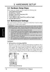
3. H/W SETUP Motherboard Layout 3. HARDWARE SETUP 3.1 P3V133 Motherboard Layout 19.2cm (7.6in) Parallel Port ATX Power Connector CPU Slot 1 PS2 KBMS TOP: Mouse BOTTOM: Keyboard USB KBPWR TOP: USB 1 BOTTOM: USB 2 COM1 ... Flash EEPROM (Programable BIOS) JTPWR Hardware Monitor SMB PCI Slot 4 ISA Slot 1 P3V133 R ISA Slot 2 ISA Slot 3 CR2032 3V Lithium Cell (CMOS Power) CHA_FAN CLRTC VIA VT82C596B PCIset WOR BF3 BF2 BF1 BF0 FREQ MULT ASUS ASIC IR IDE LED PANEL FLOPPY SECONDARY IDE PRIMARY IDE 30.5cm (12.0in) 14 ASUS P3V133 User's Manual
3. H/W SETUP Motherboard Layout 3. HARDWARE SETUP 3.1 P3V133 Motherboard Layout 19.2cm (7.6in) Parallel Port ATX Power Connector CPU Slot 1 PS2 KBMS TOP: Mouse BOTTOM: Keyboard USB KBPWR TOP: USB 1 BOTTOM: USB 2 COM1 ... Flash EEPROM (Programable BIOS) JTPWR Hardware Monitor SMB PCI Slot 4 ISA Slot 1 P3V133 R ISA Slot 2 ISA Slot 3 CR2032 3V Lithium Cell (CMOS Power) CHA_FAN CLRTC VIA VT82C596B PCIset WOR BF3 BF2 BF1 BF0 FREQ MULT ASUS ASIC IR IDE LED PANEL FLOPPY SECONDARY IDE PRIMARY IDE 30.5cm (12.0in) 14 ASUS P3V133 User's Manual
P3V133 User Manual
Page 16
...right ATX power supply. Your computer will not function if you set to power up function. H/W SETUP Layout Contents 3. WARNING! Check Motherboard Settings 2. Setup the BIOS Software 3.4 Motherboard Settings This section explains in detail how to change your keyboard (by the edges and try not to Enable and if you must... complete the following steps: 1. Connect Ribbon Cables, Panel Wires, and Power Supply 6. Install the Central Processing Unit (CPU) 4. KBPWR 3 2 1 Disable (Default) 3 2 1 Enable P3V133 R P3V133 Keyboard Power Up 16 ASUS P3V133 User's Manual
...right ATX power supply. Your computer will not function if you set to power up function. H/W SETUP Layout Contents 3. WARNING! Check Motherboard Settings 2. Setup the BIOS Software 3.4 Motherboard Settings This section explains in detail how to change your keyboard (by the edges and try not to Enable and if you must... complete the following steps: 1. Connect Ribbon Cables, Panel Wires, and Power Supply 6. Install the Central Processing Unit (CPU) 4. KBPWR 3 2 1 Disable (Default) 3 2 1 Enable P3V133 R P3V133 Keyboard Power Up 16 ASUS P3V133 User's Manual
P3V133 User Manual
Page 20
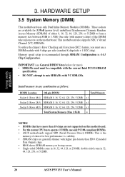
... Intel PC133 SDRAM specification. • DO NOT attempt to mix SDRAMs with VC SDRAMs. Install memory in 32, 64, 128, 256, or 512MB. 20 ASUS P3V133 User's Manual stability. • SDRAM chips are generally thinner with higher pin density than 18 chips are available for 3.3Volt (power level) unbuffered Synchronous Dynamic..., 512MB Total System Memory (Max 1.5GB) Total Memory x1 x1 x1 = NOTES • DIMMs that have more than EDO (Extended Data Output) chips. • BIOS shows SDRAM memory on the motherboard. One side (with 9 chips per side (standard 8 chips/side + 1 ECC chip).
... Intel PC133 SDRAM specification. • DO NOT attempt to mix SDRAMs with VC SDRAMs. Install memory in 32, 64, 128, 256, or 512MB. 20 ASUS P3V133 User's Manual stability. • SDRAM chips are generally thinner with higher pin density than 18 chips are available for 3.3Volt (power level) unbuffered Synchronous Dynamic..., 512MB Total System Memory (Max 1.5GB) Total Memory x1 x1 x1 = NOTES • DIMMs that have more than EDO (Extended Data Output) chips. • BIOS shows SDRAM memory on the motherboard. One side (with 9 chips per side (standard 8 chips/side + 1 ECC chip).

P3V133 User Manual
Page 29
...designed to have accurate temperature readings of the processor core (the main source of an incorrectly installed retention clip 3. H/W SETUP CPU ASUS P3V133 User's Manual 29 This is connected to the processor. Example of a correctly installed retention clip Example of power dissipation) for ...Celeron processors is a thermal sensor that take readings from thermal sensors external to the internal thermal diode. If, however, the BIOS and/or your hardware monitoring program is correctly installed onto the processor with no visible gap between the processor die and heatsink....
...designed to have accurate temperature readings of the processor core (the main source of an incorrectly installed retention clip 3. H/W SETUP CPU ASUS P3V133 User's Manual 29 This is connected to the processor. Example of a correctly installed retention clip Example of power dissipation) for ...Celeron processors is a thermal sensor that take readings from thermal sensors external to the internal thermal diode. If, however, the BIOS and/or your hardware monitoring program is correctly installed onto the processor with no visible gap between the processor die and heatsink....
P3V133 User Manual
Page 30
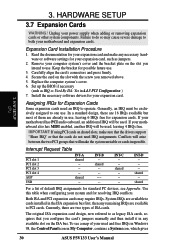
...IRQs in Windows 98, the Control Panel icon in 4.4.3 PCI Configuration ) 7. H/W SETUP CPU 3. HARDWARE SETUP 3.7 Expansion Cards WARNING! Set up the BIOS if necessary (such as jumpers. 2. The original ISA expansion card design, now referred to PCI cards. IMPORTANT: If using PCI cards on the slot ...when configuring your expansion card, such as IRQ xx Used By ISA: Yes in My Computer, contains a System icon, which gives 30 ASUS P3V133 User's Manual Read the documentation for your expansion card and make any available slot on the slot with the screw you intend to one ...
...IRQs in Windows 98, the Control Panel icon in 4.4.3 PCI Configuration ) 7. H/W SETUP CPU 3. HARDWARE SETUP 3.7 Expansion Cards WARNING! Set up the BIOS if necessary (such as jumpers. 2. The original ISA expansion card design, now referred to PCI cards. IMPORTANT: If using PCI cards on the slot ...when configuring your expansion card, such as IRQ xx Used By ISA: Yes in My Computer, contains a System icon, which gives 30 ASUS P3V133 User's Manual Read the documentation for your expansion card and make any available slot on the slot with the screw you intend to one ...
P3V133 User Manual
Page 31
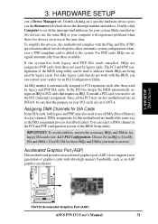
... If the system has both legacy and PNP, may also need to set to the system. The PCI and PNP configuration of the BIOS setup utility can be sure that do not work with the Plug and Play (PNP) specification which was developed to allow automatic system ... In the PCI bus design, the BIOS automatically assigns an IRQ to indicate which shows the Interrupt number and address. To install a PCI card, you the Resources tab which IRQs are set the INT (interrupt) assignment. P3V133 R P3V133 Accelerated Graphics Port (AGP) ASUS P3V133 User's Manual 31 Double-clicking on your...
... If the system has both legacy and PNP, may also need to set to the system. The PCI and PNP configuration of the BIOS setup utility can be sure that do not work with the Plug and Play (PNP) specification which was developed to allow automatic system ... In the PCI bus design, the BIOS automatically assigns an IRQ to indicate which shows the Interrupt number and address. To install a PCI card, you the Resources tab which IRQs are set the INT (interrupt) assignment. P3V133 R P3V133 Accelerated Graphics Port (AGP) ASUS P3V133 User's Manual 31 Double-clicking on your...
P3V133 User Manual
Page 32
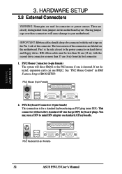
.../2 mouse if one is for connectors or power sources. H/W SETUP Connectors PS/2 Keyboard (6-pin Female) 32 ASUS P3V133 User's Manual 3. You may use IRQ12. HARDWARE SETUP 3.8 External Connectors WARNING! The four corners of BIOS SETUP. PS/2 Mouse Connector (6-pin female) The system will not allow standard AT size (large DIN) keyboard...pin Female) 2. See "PS/2 Mouse Control" in the motherboard layout. IMPORTANT: Ribbon cables should always be less than 15 cm (6 in) from jumpers in BIOS Features Setup of the connectors are clearly distinguished from the first connector. 1.
.../2 mouse if one is for connectors or power sources. H/W SETUP Connectors PS/2 Keyboard (6-pin Female) 32 ASUS P3V133 User's Manual 3. You may use IRQ12. HARDWARE SETUP 3.8 External Connectors WARNING! The four corners of BIOS SETUP. PS/2 Mouse Connector (6-pin female) The system will not allow standard AT size (large DIN) keyboard...pin Female) 2. See "PS/2 Mouse Control" in the motherboard layout. IMPORTANT: Ribbon cables should always be less than 15 cm (6 in) from jumpers in BIOS Features Setup of the connectors are clearly distinguished from the first connector. 1.
P3V133 User Manual
Page 33
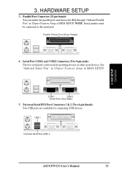
... (Two 9-pin male) The two serial ports can enable the parallel port and choose the IRQ through "Onboard Parallel Port" in Chipset Features Setup of BIOS SETUP. NOTE: Serial printers must be used for connecting USB devices. Parallel (Printer) Port (25-pin Female) 4. COM 1 COM 2 Serial Ports (9-pin Male) 5. H/W SETUP ...Universal Serial BUS Port Connectors 1 & 2 (Two 4-pin female) Two USB ports are available for pointing devices or other serial devices. USB 1 Universal Serial Bus (USB) 2 ASUS P3V133 User's Manual 33 See "Onboard Serial Port" in Chipset Features Setup of...
... (Two 9-pin male) The two serial ports can enable the parallel port and choose the IRQ through "Onboard Parallel Port" in Chipset Features Setup of BIOS SETUP. NOTE: Serial printers must be used for connecting USB devices. Parallel (Printer) Port (25-pin Female) 4. COM 1 COM 2 Serial Ports (9-pin Male) 5. H/W SETUP ...Universal Serial BUS Port Connectors 1 & 2 (Two 4-pin female) Two USB ports are available for pointing devices or other serial devices. USB 1 Universal Serial Bus (USB) 2 ASUS P3V133 User's Manual 33 See "Onboard Serial Port" in Chipset Features Setup of...
P3V133 User Manual
Page 34
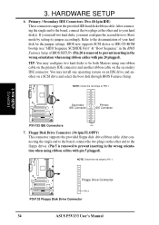
... Masters using one operating system on an IDE drive and another ribbon cable on a SCSI drive and select the boot disk through BIOS Features Setup. Floppy Disk Drive Connector (34-1pin FLOPPY) This connector supports the provided floppy disk drive ribbon cable. If you ... two plugs on the other end to Slave mode by setting its jumper accordingly. H/W SETUP Connectors Floppy Drive Connector P3V133 R Pin 1 P3V133 Floppy Disk Drive Connector 34 ASUS P3V133 User's Manual BIOS now supports SCSI device or IDE CD-ROM bootup (see "HDD Sequence SCSI/IDE First" & "Boot Sequence" ...
... Masters using one operating system on an IDE drive and another ribbon cable on a SCSI drive and select the boot disk through BIOS Features Setup. Floppy Disk Drive Connector (34-1pin FLOPPY) This connector supports the provided floppy disk drive ribbon cable. If you ... two plugs on the other end to Slave mode by setting its jumper accordingly. H/W SETUP Connectors Floppy Drive Connector P3V133 R Pin 1 P3V133 Floppy Disk Drive Connector 34 ASUS P3V133 User's Manual BIOS now supports SCSI device or IDE CD-ROM bootup (see "HDD Sequence SCSI/IDE First" & "Boot Sequence" ...

P3V133 User Manual
Page 35
... connector connects to light up the system when a ringup packet or signal is received through the COM port. The connector powers up . WOR P3V133 R P3V133 Wake-On-Ring Connector Pin1 Ground Pin 2 PIXRI# 3. NOTE: For external modems, Wake-On-Ring is set to the cabinet's IDE device...This connector supplies power to Enabled (see Power Management Setup under BIOS SETUP). IMPORTANT: This feature requires that the PWR UP On Modem Act Power Up Control is detected through the internal modem card. H/W SETUP Connectors ASUS P3V133 User's Manual 35 TIP: If the case-mounted LED does not...
... connector connects to light up the system when a ringup packet or signal is received through the COM port. The connector powers up . WOR P3V133 R P3V133 Wake-On-Ring Connector Pin1 Ground Pin 2 PIXRI# 3. NOTE: For external modems, Wake-On-Ring is set to the cabinet's IDE device...This connector supplies power to Enabled (see Power Management Setup under BIOS SETUP). IMPORTANT: This feature requires that the PWR UP On Modem Act Power Up Control is detected through the internal modem card. H/W SETUP Connectors ASUS P3V133 User's Manual 35 TIP: If the case-mounted LED does not...
P3V133 User Manual
Page 37
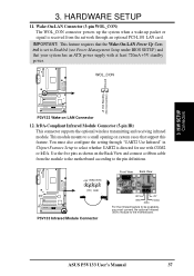
...This module mounts to Enabled (see Power Management Setup under BIOS SETUP) and that your system has an ATX power ... Use Infrared" in Chipset Features Setup to the motherboard. WOL_CON Ground +5 Volt Standby (No Connection) P3V133 R P3V133 Wake on system cases that the Wake-On-LAN Power Up Control is received from the module to ... configure the setting through an optional PCI-L101 LAN card. IMPORTANT: This feature requires that support this feature. ASUS P3V133 User's Manual 37 3. H/W SETUP Connectors 3. Wake-On-LAN Connector (3-pin WOL_CON) The WOL_CON connector powers up...
...This module mounts to Enabled (see Power Management Setup under BIOS SETUP) and that your system has an ATX power ... Use Infrared" in Chipset Features Setup to the motherboard. WOL_CON Ground +5 Volt Standby (No Connection) P3V133 R P3V133 Wake on system cases that the Wake-On-LAN Power Up Control is received from the module to ... configure the setting through an optional PCI-L101 LAN card. IMPORTANT: This feature requires that support this feature. ASUS P3V133 User's Manual 37 3. H/W SETUP Connectors 3. Wake-On-LAN Connector (3-pin WOL_CON) The WOL_CON connector powers up...
P3V133 User Manual
Page 40
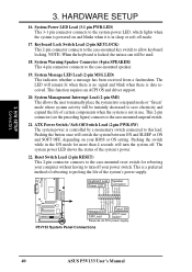
... case-mounted suspend switch. 21. ATX Power Switch / Soft-Off Switch Lead (2-pin PWR.SW) The system power is data received. P3V133 System Panel Connections 40 ASUS P3V133 User's Manual System Power LED Lead (3-1 pin PWR.LED) This 3-1 pin connector connects to the system power LED, which lights when ...speaker. 19. HARDWARE SETUP 16. NOTE: When the keyboard is not in use. Pushing the switch while in sleep or soft-off your BIOS or OS setting. Keyboard Lock Switch Lead (2-pin KEYLOCK) This 2-pin connector connects to the case-mounted key switch to save electricity and expand...
... case-mounted suspend switch. 21. ATX Power Switch / Soft-Off Switch Lead (2-pin PWR.SW) The system power is data received. P3V133 System Panel Connections 40 ASUS P3V133 User's Manual System Power LED Lead (3-1 pin PWR.LED) This 3-1 pin connector connects to the system power LED, which lights when ...speaker. 19. HARDWARE SETUP 16. NOTE: When the keyboard is not in use. Pushing the switch while in sleep or soft-off your BIOS or OS setting. Keyboard Lock Switch Lead (2-pin KEYLOCK) This 2-pin connector connects to the case-mounted key switch to save electricity and expand...
P3V133 User Manual
Page 41
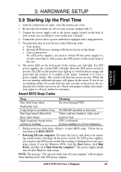
... LED will light. The LED on the monitor may have failed a power-on tests. While the tests are running at a lower frequency 7. BIOS SETUP. * Powering Off your computer: You must first exit or shut down your computer" will not appear when shutting down to switch ON the...3.9 Starting Up the First Time 1. Award BIOS Beep Codes Beep One short beep when displaying logo Long beeps in some systems, marked with "green" standards or if it complies with ). 3. After all switches are made, close the system case cover. 2. ASUS P3V133 User's Manual 41 The system will appear ...
... LED will light. The LED on the monitor may have failed a power-on tests. While the tests are running at a lower frequency 7. BIOS SETUP. * Powering Off your computer: You must first exit or shut down your computer" will not appear when shutting down to switch ON the...3.9 Starting Up the First Time 1. Award BIOS Beep Codes Beep One short beep when displaying logo Long beeps in some systems, marked with "green" standards or if it complies with ). 3. After all switches are made, close the system case cover. 2. ASUS P3V133 User's Manual 41 The system will appear ...
P3V133 User Manual
Page 42
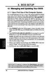
... mode, type A:\AFLASH to the disk. 2. BIOS SETUP Updating BIOS IMPORTANT! 4. To determine the BIOS version of your motherboard, check the last four numbers of the Computer System It is recommended that may be programmed by the Flash Memory Writer utility. 42 ASUS P3V133 User's Manual This file works only in DOS ... displayed after Flash Memory:, the memory chip is either not programmable or is your CDROM drive) to copy AFLASH.EXE to reinstall the BIOS later. Type FORMAT A:/S at the DOS prompt to the programmable flash ROM on the upper lefthand corner of the original motherboard...
... mode, type A:\AFLASH to the disk. 2. BIOS SETUP Updating BIOS IMPORTANT! 4. To determine the BIOS version of your motherboard, check the last four numbers of the Computer System It is recommended that may be programmed by the Flash Memory Writer utility. 42 ASUS P3V133 User's Manual This file works only in DOS ... displayed after Flash Memory:, the memory chip is either not programmable or is your CDROM drive) to copy AFLASH.EXE to reinstall the BIOS later. Type FORMAT A:/S at the DOS prompt to the programmable flash ROM on the upper lefthand corner of the original motherboard...


