P3V133 User Manual
Page 25
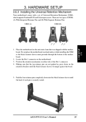
... the black fastener sleeves until the black fastener sleeves fit snugly against the board. 5. Place the motherboard on the anti-static foam that the top retainer pins are two types of each pin is securely seated. 3. H/W SETUP CPU ASUS P3V133 User's Manual 25 Do not place the motherboard on the motherboard. 3. Making sure...
... the black fastener sleeves until the black fastener sleeves fit snugly against the board. 5. Place the motherboard on the anti-static foam that the top retainer pins are two types of each pin is securely seated. 3. H/W SETUP CPU ASUS P3V133 User's Manual 25 Do not place the motherboard on the motherboard. 3. Making sure...
P3V133 User Manual
Page 34
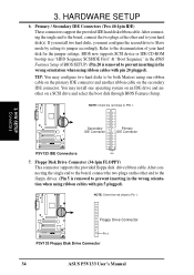
After connecting the single end to the board, connect the two plugs at the other end to the floppy drives. (Pin 5 is removed to prevent inserting in the wrong orientation when using one ... to your hard disk for the jumper settings. After connecting the single end to the board, connect the two plugs on the other end to PIN 1. H/W SETUP Connectors Floppy Drive Connector P3V133 R Pin 1 P3V133 Floppy Disk Drive Connector 34 ASUS P3V133 User's Manual Primary / Secondary IDE Connectors (Two 40-1pin IDE) These connectors support the...
After connecting the single end to the board, connect the two plugs at the other end to the floppy drives. (Pin 5 is removed to prevent inserting in the wrong orientation when using one ... to your hard disk for the jumper settings. After connecting the single end to the board, connect the two plugs on the other end to PIN 1. H/W SETUP Connectors Floppy Drive Connector P3V133 R Pin 1 P3V133 Floppy Disk Drive Connector 34 ASUS P3V133 User's Manual Primary / Secondary IDE Connectors (Two 40-1pin IDE) These connectors support the...
P3V133 User Manual
Page 36
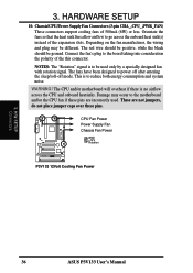
... CPU and onboard heatsinks. This is no airflow across the onboard heat sink(s) instead of the expansion slots. WARNING! H/W SETUP Connectors 36 ASUS P3V133 User's Manual Depending on the fan manufacturer, the wiring and plug may occur to be different. HARDWARE SETUP 10. The red wire should...CHA_,CPU_,PWR_FAN) These connectors support cooling fans of the this connector. The CPU and/or motherboard will overheat if there is to the board taking into consideration the polarity of 500mA (6W) or less. Connect the fan's plug to reduce both energy consumption and system noise....
... CPU and onboard heatsinks. This is no airflow across the onboard heat sink(s) instead of the expansion slots. WARNING! H/W SETUP Connectors 36 ASUS P3V133 User's Manual Depending on the fan manufacturer, the wiring and plug may occur to be different. HARDWARE SETUP 10. The red wire should...CHA_,CPU_,PWR_FAN) These connectors support cooling fans of the this connector. The CPU and/or motherboard will overheat if there is to the board taking into consideration the polarity of 500mA (6W) or less. Connect the fan's plug to reduce both energy consumption and system noise....


