P3V133 User Manual
Page 1
® P3V133 PC133 Motherboard USER'S MANUAL
® P3V133 PC133 Motherboard USER'S MANUAL
P3V133 User Manual
Page 4
... First Use of the Computer System 42 4.1.2 Updating BIOS Procedures (only when necessary) ......... 43 4.2 BIOS Setup Program 45 4.2.1 BIOS Menu Bar 46 4.2.2 Legend Bar 46 4 ASUS P3V133 User's Manual INTRODUCTION 7 1.1 How This Manual Is Organized 7 1.2 Item Checklist 7 2. FEATURES 8 2.1 The ASUS P3V133 8 2.1.1 Specifications 8 2.1.2 Special Features 10 2.1.3 Performance Features 10 2.1.4 Intelligence 11 2.2 P3V133 Motherboard Components 12 3.
... First Use of the Computer System 42 4.1.2 Updating BIOS Procedures (only when necessary) ......... 43 4.2 BIOS Setup Program 45 4.2.1 BIOS Menu Bar 46 4.2.2 Legend Bar 46 4 ASUS P3V133 User's Manual INTRODUCTION 7 1.1 How This Manual Is Organized 7 1.2 Item Checklist 7 2. FEATURES 8 2.1 The ASUS P3V133 8 2.1.1 Specifications 8 2.1.2 Special Features 10 2.1.3 Performance Features 10 2.1.4 Intelligence 11 2.2 P3V133 Motherboard Components 12 3.
P3V133 User Manual
Page 5
... 69 4.7 Exit Menu 71 5. SOFTWARE SETUP 73 5.1 Operating Systems 73 5.1.1 Windows 98 First Time Installation 73 5.2 P3V Series Motherboard Support CD 74 5.3 ASUS PC Probe Setup 75 5.4 Adobe Acrobat Reader 76 5.5 Install VIA 4 in 1 Driver 77 5.6 Install PC-Cillin 78 5.7 ... 7.1 ASUS S370-133 CPU Card 87 7.1.1 Using the ASUS S370-133 87 7.1.2 Setting up the ASUS S370-133 88 7.1.3 ASUS S370-133 Jumper Settings 88 7.2 ASUS PCI-L101 Fast Ethernet Card 89 7.2.1 Features 90 7.2.2 Software Driver Support 90 7.2.3 Questions and Answers 90 7.3 Glossary 91 ASUS P3V133 User's...
... 69 4.7 Exit Menu 71 5. SOFTWARE SETUP 73 5.1 Operating Systems 73 5.1.1 Windows 98 First Time Installation 73 5.2 P3V Series Motherboard Support CD 74 5.3 ASUS PC Probe Setup 75 5.4 Adobe Acrobat Reader 76 5.5 Install VIA 4 in 1 Driver 77 5.6 Install PC-Cillin 78 5.7 ... 7.1 ASUS S370-133 CPU Card 87 7.1.1 Using the ASUS S370-133 87 7.1.2 Setting up the ASUS S370-133 88 7.1.3 ASUS S370-133 Jumper Settings 88 7.2 ASUS PCI-L101 Fast Ethernet Card 89 7.2.1 Features 90 7.2.2 Software Driver Support 90 7.2.3 Questions and Answers 90 7.3 Glossary 91 ASUS P3V133 User's...
P3V133 User Manual
Page 7
...software Reference material for the included software Optional items and general reference 1.2 Item Checklist Check that your retailer. (1) ASUS Motherboard (1) Universal Retention Mechanism for SECC2/SECC/SEPP processors (1) Ribbon cable for master and slave UltraDMA/66 or UltraDMA/... drives (1) Bag of spare jumper caps (1) Support CD with drivers and utilities (1) This Motherboard User's Manual ASUS IrDA-compliant infrared module (optional) ASUS S370 Series CPU cards (optional) ASUS PCI-L101 Wake-On-LAN 10/100 Ethernet Card (optional) ASUS P3V133 User's Manual 7 SOFTWARE REFERENCE 7.
...software Reference material for the included software Optional items and general reference 1.2 Item Checklist Check that your retailer. (1) ASUS Motherboard (1) Universal Retention Mechanism for SECC2/SECC/SEPP processors (1) Ribbon cable for master and slave UltraDMA/66 or UltraDMA/... drives (1) Bag of spare jumper caps (1) Support CD with drivers and utilities (1) This Motherboard User's Manual ASUS IrDA-compliant infrared module (optional) ASUS S370 Series CPU cards (optional) ASUS PCI-L101 Wake-On-LAN 10/100 Ethernet Card (optional) ASUS P3V133 User's Manual 7 SOFTWARE REFERENCE 7.
P3V133 User Manual
Page 8
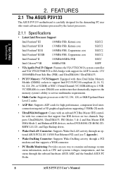
...RW, LS-120, and Tape Backup drives. • Wake-On-LAN Connector: Supports Wake-On-LAN activity through the onboard hardware ASUS ASIC and the bundled ASUS PC Probe. 8 ASUS P3V133 User's Manual 2. FEA TURES Specifications 2. Supports UltraDMA/66, UltraDMA/33, PIO Modes 3 & 4 and Bus Master IDE DMA ...cache. • AGP Slot: Supports AGP cards for AGP 2x mode; 133/ 100/66MHz Front Side Bus (FSB); FEATURES 2.1 The ASUS P3V133 The ASUS P3V133 motherboard is a new DRAM core architecture that supports a WOR connector. • PC Health Monitoring: Provides an easy way to 1.5GB.
...RW, LS-120, and Tape Backup drives. • Wake-On-LAN Connector: Supports Wake-On-LAN activity through the onboard hardware ASUS ASIC and the bundled ASUS PC Probe. 8 ASUS P3V133 User's Manual 2. FEA TURES Specifications 2. Supports UltraDMA/66, UltraDMA/33, PIO Modes 3 & 4 and Bus Master IDE DMA ...cache. • AGP Slot: Supports AGP cards for AGP 2x mode; 133/ 100/66MHz Front Side Bus (FSB); FEATURES 2.1 The ASUS P3V133 The ASUS P3V133 motherboard is a new DRAM core architecture that supports a WOR connector. • PC Health Monitoring: Provides an easy way to 1.5GB.
P3V133 User Manual
Page 10
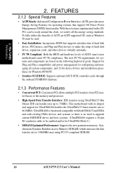
... a 40-pin 80-conductor cable to be enabled and/or for Windows95/98/NT . • Symbios SCSI BIOS: Supports optional ASUS SCSI controller cards through the onboard SYMBIOS firmware. 2.1.3 Performance Features • Concurrent PCI: Concurrent PCI allows multiple PCI transfers from PCI...8226; High-Speed Data Transfer Interface: IDE transfers using PC133-compliant SDRAM. 10 ASUS P3V133 User's Manual To fully utilize the benefits of ASUS smart series motherboards meet PC'98 compliancy. This motherboard with existing DMA devices and systems so there is backward compatible with both DMA...
... a 40-pin 80-conductor cable to be enabled and/or for Windows95/98/NT . • Symbios SCSI BIOS: Supports optional ASUS SCSI controller cards through the onboard SYMBIOS firmware. 2.1.3 Performance Features • Concurrent PCI: Concurrent PCI allows multiple PCI transfers from PCI...8226; High-Speed Data Transfer Interface: IDE transfers using PC133-compliant SDRAM. 10 ASUS P3V133 User's Manual To fully utilize the benefits of ASUS smart series motherboards meet PC'98 compliancy. This motherboard with existing DMA devices and systems so there is backward compatible with both DMA...
P3V133 User Manual
Page 11
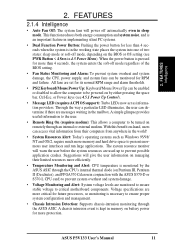
... enters the soft-off mode, depending on by the ASUS ASIC through an internal or external modem. When the power button is kept in the mailbox. Voltage specifications are used up to critical motherboard components. A chassis intrusion event is pressed for more memory... supply, and system fans can determine if there are monitored to ensure stable voltage to prevent possible application crashes. FEA TURES Intelligence 2. ASUS P3V133 User's Manual 11 FEATURES 2.1.4 Intelligence • Auto Fan Off: The system fans will power off automatically even in the world! ...
... enters the soft-off mode, depending on by the ASUS ASIC through an internal or external modem. When the power button is kept in the mailbox. Voltage specifications are used up to critical motherboard components. A chassis intrusion event is pressed for more memory... supply, and system fans can determine if there are monitored to ensure stable voltage to prevent possible application crashes. FEA TURES Intelligence 2. ASUS P3V133 User's Manual 11 FEATURES 2.1.4 Intelligence • Auto Fan Off: The system fans will power off automatically even in the world! ...
P3V133 User Manual
Page 12
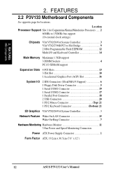
FEATURES 2.2 P3V133 Motherboard Components See opposite page for Coppermine/Katmai/Mendecino Processors ...... 2 66MHz to 150MHz bus support (16 external clock settings) Chipsets VIA VT82C693A System Controller 3 VIA VT82C596B ... 7 Hardware Monitoring Hardware Monitor 11 3 Fan Power and Speed Monitoring Connectors Power ATX Power Supply Connector 1 Form Factor ATX, 19.2cm x 30.5cm (7.6" x 12") 12 ASUS P3V133 User's Manual Location Processor Support Slot 1 for locations. 2. FEA TURES MB Components 2.
FEATURES 2.2 P3V133 Motherboard Components See opposite page for Coppermine/Katmai/Mendecino Processors ...... 2 66MHz to 150MHz bus support (16 external clock settings) Chipsets VIA VT82C693A System Controller 3 VIA VT82C596B ... 7 Hardware Monitoring Hardware Monitor 11 3 Fan Power and Speed Monitoring Connectors Power ATX Power Supply Connector 1 Form Factor ATX, 19.2cm x 30.5cm (7.6" x 12") 12 ASUS P3V133 User's Manual Location Processor Support Slot 1 for locations. 2. FEA TURES MB Components 2.

P3V133 User Manual
Page 14
H/W SETUP Motherboard Layout 3. HARDWARE SETUP 3.1 P3V133 Motherboard Layout 19.2cm (7.6in) Parallel Port ATX Power Connector CPU Slot 1 PS2 KBMS TOP: Mouse BOTTOM: Keyboard USB KBPWR TOP: USB 1 BOTTOM: USB 2 COM1 PWR_FAN ... WOL_CON Accelerated Graphics Port Multi-I/O CHASIS PCI Slot 1 PCI Slot 2 PCI Slot 3 2Mb Flash EEPROM (Programable BIOS) JTPWR Hardware Monitor SMB PCI Slot 4 ISA Slot 1 P3V133 R ISA Slot 2 ISA Slot 3 CR2032 3V Lithium Cell (CMOS Power) CHA_FAN CLRTC VIA VT82C596B PCIset WOR BF3 BF2 BF1 BF0 FREQ MULT...
H/W SETUP Motherboard Layout 3. HARDWARE SETUP 3.1 P3V133 Motherboard Layout 19.2cm (7.6in) Parallel Port ATX Power Connector CPU Slot 1 PS2 KBMS TOP: Mouse BOTTOM: Keyboard USB KBPWR TOP: USB 1 BOTTOM: USB 2 COM1 PWR_FAN ... WOL_CON Accelerated Graphics Port Multi-I/O CHASIS PCI Slot 1 PCI Slot 2 PCI Slot 3 2Mb Flash EEPROM (Programable BIOS) JTPWR Hardware Monitor SMB PCI Slot 4 ISA Slot 1 P3V133 R ISA Slot 2 ISA Slot 3 CR2032 3V Lithium Cell (CMOS Power) CHA_FAN CLRTC VIA VT82C596B PCIset WOR BF3 BF2 BF1 BF0 FREQ MULT...
P3V133 User Manual
Page 15
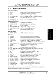
HARDWARE SETUP 3.2 Layout Contents Motherboard Settings 1) KBPWR 2) VIO 3) VCORE 4) FS0, FS1, FS2, FS3 5) MS0, MS1 6) BF0, BF1, BF2, BF3 p. 16 Keyboard...Connector (3 pins) 12) IR p. 37 Infrared Port Module Connector (5 pins) 13) SMB p. 38 SMBus Connector (3 pins) 14) ATXPWR p. 39 ATX Motherboard Power Connector (20 pins) 15) CHASIS p. 39 Chassis Intrusion Alarm Lead (4-1 pins) 16) PWR.LED (PANEL) p. 40 System Power LED Lead (3-1...290H-297H so legacy ISA cards must not use this address otherwise conflicts will occur. ASUS P3V133 User's Manual 15 H/W SETUP Layout Contents 3. 3.
HARDWARE SETUP 3.2 Layout Contents Motherboard Settings 1) KBPWR 2) VIO 3) VCORE 4) FS0, FS1, FS2, FS3 5) MS0, MS1 6) BF0, BF1, BF2, BF3 p. 16 Keyboard...Connector (3 pins) 12) IR p. 37 Infrared Port Module Connector (5 pins) 13) SMB p. 38 SMBus Connector (3 pins) 14) ATXPWR p. 39 ATX Motherboard Power Connector (20 pins) 15) CHASIS p. 39 Chassis Intrusion Alarm Lead (4-1 pins) 16) PWR.LED (PANEL) p. 40 System Power LED Lead (3-1...290H-297H so legacy ISA cards must not use this address otherwise conflicts will occur. ASUS P3V133 User's Manual 15 H/W SETUP Layout Contents 3. 3.
P3V133 User Manual
Page 16
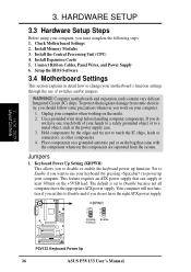
...) 4. Use a grounded wrist strap before handling computer components. H/W SETUP Layout Contents 3. KBPWR 3 2 1 Disable (Default) 3 2 1 Enable P3V133 R P3V133 Keyboard Power Up 16 ASUS P3V133 User's Manual HARDWARE SETUP 3.3 Hardware Setup Steps Before using your computer, you work on your motherboard's function settings through the use your computer. Place components on a grounded antistatic pad or on the...
...) 4. Use a grounded wrist strap before handling computer components. H/W SETUP Layout Contents 3. KBPWR 3 2 1 Disable (Default) 3 2 1 Enable P3V133 R P3V133 Keyboard Power Up 16 ASUS P3V133 User's Manual HARDWARE SETUP 3.3 Hardware Setup Steps Before using your computer, you work on your motherboard's function settings through the use your computer. Place components on a grounded antistatic pad or on the...
P3V133 User Manual
Page 17
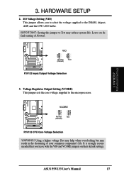
H/W SETUP Motherboard Settings 3. HARDWARE SETUP 2. Voltage Regulator Output Setting (VCORE) This jumper sets the core voltage supplied to the DRAM, chipset, AGP, and the CPU's I /O Voltage Setting (... Voltage Selection 3. IMPORTANT: Setting this jumper to Test may result in the shortening of Normal. ASUS P3V133 User's Manual 17 Using a higher voltage Test may help when overclocking but may reduce system life. VCORE 3 2 1 Normal (Default) 3 2 1 Test P3V133 R P3V133 CPU Core Voltage Selection WARNING! It is strongly recommended that you to select the voltage...
H/W SETUP Motherboard Settings 3. HARDWARE SETUP 2. Voltage Regulator Output Setting (VCORE) This jumper sets the core voltage supplied to the DRAM, chipset, AGP, and the CPU's I /O Voltage Setting (... Voltage Selection 3. IMPORTANT: Setting this jumper to Test may result in the shortening of Normal. ASUS P3V133 User's Manual 17 Using a higher voltage Test may help when overclocking but may reduce system life. VCORE 3 2 1 Normal (Default) 3 2 1 Test P3V133 R P3V133 CPU Core Voltage Selection WARNING! It is strongly recommended that you to select the voltage...
P3V133 User Manual
Page 18
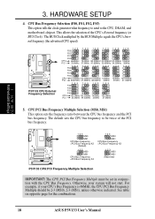
... (MS0), 2-3 (MS1), unless otherwise indicated. The BUS Clock multiplied by the BUS Multiple equals the CPU's Internal frequency (the advertised CPU speed). P3V133 R 123 MS0 MS1 CPU Bus Frequency =PCI Bus Frequency X2 (Default) 123 MS0 MS1 CPU Bus Frequency =PCI Bus Frequency X4 123 MS0 MS1 ...35MHz 37.5MHz 5. The default sets the CPU bus frequency to the CPU, DRAM, and motherboard chipset. For example, if your system will not start. See table on opposite page for the combinations. 18 ASUS P3V133 User's Manual CPU Bus Frequency Selection (FS0, FS1, FS2, FS3) This option tells ...
... (MS0), 2-3 (MS1), unless otherwise indicated. The BUS Clock multiplied by the BUS Multiple equals the CPU's Internal frequency (the advertised CPU speed). P3V133 R 123 MS0 MS1 CPU Bus Frequency =PCI Bus Frequency X2 (Default) 123 MS0 MS1 CPU Bus Frequency =PCI Bus Frequency X4 123 MS0 MS1 ...35MHz 37.5MHz 5. The default sets the CPU bus frequency to the CPU, DRAM, and motherboard chipset. For example, if your system will not start. See table on opposite page for the combinations. 18 ASUS P3V133 User's Manual CPU Bus Frequency Selection (FS0, FS1, FS2, FS3) This option tells ...
P3V133 User Manual
Page 19
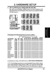
... BF3 BF2 BF1 BF0 4.5X (9/2) 5.0X (5/1) 5.5x (11/2) 6.0x (6/1) 6.5X (13/2) 12 3 BF3 12 3 12 3 BF2 BF1 BF0 7.0X (7/1) 7.5X (15/2) 8.0X (8/1) 3. ASUS P3V133 User's Manual 19 Multiple) CPU:PCI FS0 FS1 FS2 FS3 BF0 BF1 BF2 BF3 MS0 MS1 [1-2] [1-2] [1-2] [1-2] [1-2] [1-2] [1-2] [2-3] [2-3] [1-2] [1-2] [1-2] [1-2] [1-2] [2-3] [1-2] [1-2] [2-3] [2-3] [1-2] Pentium... to the onboard power regulator. It may result in conjunction with the CPU Bus Frequency. H/W SETUP Motherboard Settings Set the jumpers by the Internal speed of the CPU and the CPU's External frequency. These must be ...
... BF3 BF2 BF1 BF0 4.5X (9/2) 5.0X (5/1) 5.5x (11/2) 6.0x (6/1) 6.5X (13/2) 12 3 BF3 12 3 12 3 BF2 BF1 BF0 7.0X (7/1) 7.5X (15/2) 8.0X (8/1) 3. ASUS P3V133 User's Manual 19 Multiple) CPU:PCI FS0 FS1 FS2 FS3 BF0 BF1 BF2 BF3 MS0 MS1 [1-2] [1-2] [1-2] [1-2] [1-2] [1-2] [1-2] [2-3] [2-3] [1-2] [1-2] [1-2] [1-2] [1-2] [2-3] [1-2] [1-2] [2-3] [2-3] [1-2] Pentium... to the onboard power regulator. It may result in conjunction with the CPU Bus Frequency. H/W SETUP Motherboard Settings Set the jumpers by the Internal speed of the CPU and the CPU's External frequency. These must be ...
P3V133 User Manual
Page 20
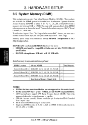
... screen. • Single-sided DIMMs come in 32, 64, 128, 256, or 512MB. 20 ASUS P3V133 User's Manual Memory speed setup is the memory of choice for more) • SDRAMs used must use only PC100-compliant DIMMs. • ASUS motherboards support SPD (Serial Presence Detect) DIMMs. This is recommended through SDRAM Configuration in 16...
... screen. • Single-sided DIMMs come in 32, 64, 128, 256, or 512MB. 20 ASUS P3V133 User's Manual Memory speed setup is the memory of choice for more) • SDRAMs used must use only PC100-compliant DIMMs. • ASUS motherboards support SPD (Serial Presence Detect) DIMMs. This is recommended through SDRAM Configuration in 16...
P3V133 User Manual
Page 21
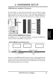
... Procedures: Insert the module(s) as shown. Lock 88 Pins P3V133 R 60 Pins 20 Pins P3V133 168-Pin DIMM Memory Sockets The DIMMs must tell your retailer the correct DIMM type before purchasing. Because the number of pins are different on the motherboard. This motherboard supports four clock signals. DRAM SIMM modules have the same... wrong type from being inserted into the DIMM slot on either side of the breaks, the module will only fit in the orientation as shown. ASUS P3V133 User's Manual 21 H/W SETUP System Memory 3.
... Procedures: Insert the module(s) as shown. Lock 88 Pins P3V133 R 60 Pins 20 Pins P3V133 168-Pin DIMM Memory Sockets The DIMMs must tell your retailer the correct DIMM type before purchasing. Because the number of pins are different on the motherboard. This motherboard supports four clock signals. DRAM SIMM modules have the same... wrong type from being inserted into the DIMM slot on either side of the breaks, the module will only fit in the orientation as shown. ASUS P3V133 User's Manual 21 H/W SETUP System Memory 3.
P3V133 User Manual
Page 23
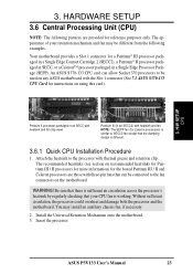
... more information) for the boxed Pentium III / II and Celeron processors are provided for reference purposes only. ASUS P3V133 User's Manual 23 The appearance of your CPU fan is different. 3.6.1 Quick CPU Installation Procedure 1. Your motherboard provides a Slot 1 connector for a Pentium® III processor packaged in a Single Edge Contact Cartridge 2 (SECC2), a Pentium®...
... more information) for the boxed Pentium III / II and Celeron processors are provided for reference purposes only. ASUS P3V133 User's Manual 23 The appearance of your CPU fan is different. 3.6.1 Quick CPU Installation Procedure 1. Your motherboard provides a Slot 1 connector for a Pentium® III processor packaged in a Single Edge Contact Cartridge 2 (SECC2), a Pentium®...
P3V133 User Manual
Page 25
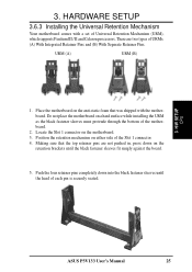
Locate the Slot 1 connector on a hard surface while installing the URM as the black fastener sleeves must protrude through the bottom of the motherboard. 2. H/W SETUP CPU ASUS P3V133 User's Manual 25 There are not pushed in, press down into the black fastener sleeves until the black fastener sleeves fit snugly against the board. 5. ...
Locate the Slot 1 connector on a hard surface while installing the URM as the black fastener sleeves must protrude through the bottom of the motherboard. 2. H/W SETUP CPU ASUS P3V133 User's Manual 25 There are not pushed in, press down into the black fastener sleeves until the black fastener sleeves fit snugly against the board. 5. ...
P3V133 User Manual
Page 26
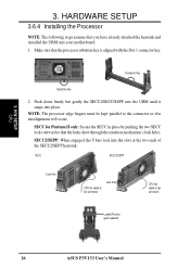
.../SEPP: When engaged, the T-bars lock into place. NOTE: The processor edge fingers must be kept parallel to fan connector Locked Position (push upward) 26 ASUS P3V133 User's Manual H/W SETUP CPU 3. Connector Key Substrate Key 2. Make sure that the locks show through the retention mechanism's lock holes. SECC for Pentium II only.../SEPP heatsink. HARDWARE SETUP 3.6.4 Installing the Processor NOTE: The following steps assume that you have already attached the heatsink and installed the URM into your motherboard. 1.
.../SEPP: When engaged, the T-bars lock into place. NOTE: The processor edge fingers must be kept parallel to fan connector Locked Position (push upward) 26 ASUS P3V133 User's Manual H/W SETUP CPU 3. Connector Key Substrate Key 2. Make sure that the locks show through the retention mechanism's lock holes. SECC for Pentium II only.../SEPP heatsink. HARDWARE SETUP 3.6.4 Installing the Processor NOTE: The following steps assume that you have already attached the heatsink and installed the URM into your motherboard. 1.
P3V133 User Manual
Page 27
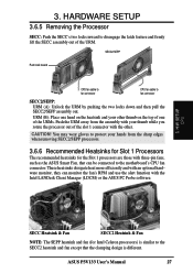
... RPM and use the alert function with your hands from the assembly with the Intel LANDesk Client Manager (LDCM) or the ASUS PC Probe software. 3. ASUS P3V133 User's Manual 27 CAUTION! These heatsinks dissipate heat more efficiently and with an optional hardware monitor, they can be connected to...firmly lift the SECC assembly out of the slot 1 connector with three-pin fans, such as the ASUS Smart Fan, that the clamping design is different. You may wear gloves to the motherboard's CPU fan connector. H/W SETUP CPU SECC Heatsink & Fan SECC2 Heatsink & Fan NOTE: The SEPP ...
... RPM and use the alert function with your hands from the assembly with the Intel LANDesk Client Manager (LDCM) or the ASUS PC Probe software. 3. ASUS P3V133 User's Manual 27 CAUTION! These heatsinks dissipate heat more efficiently and with an optional hardware monitor, they can be connected to...firmly lift the SECC assembly out of the slot 1 connector with three-pin fans, such as the ASUS Smart Fan, that the clamping design is different. You may wear gloves to the motherboard's CPU fan connector. H/W SETUP CPU SECC Heatsink & Fan SECC2 Heatsink & Fan NOTE: The SEPP ...


