P3V133 User Manual
Page 8
...-LAN Connector: Supports Wake-On-LAN activity through a PCI modem card that supports a WOR connector. • PC Health Monitoring: Provides an easy way to service multimedia requirements. • Multi-Cache: Supports processors with 512, 256, 128, or 0KB Pipelined Burst Level 2 cache. • AGP Slot: Supports AGP cards for high performance, component level interconnection targeted at 3D graphical applications supporting 133MHz 2X mode. • UltraDMA/66 Support: Comes with an onboard PCI Bus Master IDE controller...
...-LAN Connector: Supports Wake-On-LAN activity through a PCI modem card that supports a WOR connector. • PC Health Monitoring: Provides an easy way to service multimedia requirements. • Multi-Cache: Supports processors with 512, 256, 128, or 0KB Pipelined Burst Level 2 cache. • AGP Slot: Supports AGP cards for high performance, component level interconnection targeted at 3D graphical applications supporting 133MHz 2X mode. • UltraDMA/66 Support: Comes with an onboard PCI Bus Master IDE controller...
P3V133 User Manual
Page 10
... the memory and processor. • High-Speed Data Transfer Interface: IDE transfers using PC133-compliant SDRAM. 10 ASUS P3V133 User's Manual FEATURES 2.1.2 Special Features • ACPI Ready: Advanced Configuration Power Interface (ACPI) provides more Energy Saving Features for Windows95/98/NT . • Symbios SCSI BIOS: Supports optional ASUS SCSI controller cards through the onboard SYMBIOS firmware. 2.1.3 Performance Features • Concurrent PCI: Concurrent PCI allows multiple PCI transfers from PCI master busses to 1066MB/s max using UltraDMA/33 Bus Master IDE...
... the memory and processor. • High-Speed Data Transfer Interface: IDE transfers using PC133-compliant SDRAM. 10 ASUS P3V133 User's Manual FEATURES 2.1.2 Special Features • ACPI Ready: Advanced Configuration Power Interface (ACPI) provides more Energy Saving Features for Windows95/98/NT . • Symbios SCSI BIOS: Supports optional ASUS SCSI controller cards through the onboard SYMBIOS firmware. 2.1.3 Performance Features • Concurrent PCI: Concurrent PCI allows multiple PCI transfers from PCI master busses to 1066MB/s max using UltraDMA/33 Bus Master IDE...
P3V133 User Manual
Page 11
... ASUS ASIC through an internal or external modem. ASUS P3V133 User's Manual 11 Through the way a particular LED illuminates, the user can be turned on remotely through the CPU's internal thermal diode (on battery power for RPM and failure. Suggestions will power off mode regardless of two states: sleep mode or soft-off mode, depending on the BIOS or OS setting (see 4.5.1 Power Up Control). • Message LED (requires ACPI OS support): Turbo LEDs now act as Windows...
... ASUS ASIC through an internal or external modem. ASUS P3V133 User's Manual 11 Through the way a particular LED illuminates, the user can be turned on remotely through the CPU's internal thermal diode (on battery power for RPM and failure. Suggestions will power off mode regardless of two states: sleep mode or soft-off mode, depending on the BIOS or OS setting (see 4.5.1 Power Up Control). • Message LED (requires ACPI OS support): Turbo LEDs now act as Windows...
P3V133 User Manual
Page 12
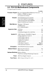
...) Slot 16 System I/O 2 IDE Connectors (UltraDMA33 Support 6 1 Floppy Disk Driver Connector 5 1 Serial COM1 Connector 19 1 Serial COM2 Connector 17 1 Parallel Port Connector 18 2 USB Connectors 20 1 PS/2 Mouse Connector Top) 21 1 PS/2 Keyboard Connector Bottom) 21 3D Graphics VIA VT82C693A System Controller 3 Network Feature Wake-On-LAN Connector 15 Wake-On-Ring Connector 7 Hardware Monitoring Hardware Monitor 11 3 Fan Power and Speed Monitoring Connectors Power ATX Power Supply Connector 1 Form Factor ATX, 19.2cm x 30.5cm (7.6" x 12") 12 ASUS P3V133 User's Manual 2.
...) Slot 16 System I/O 2 IDE Connectors (UltraDMA33 Support 6 1 Floppy Disk Driver Connector 5 1 Serial COM1 Connector 19 1 Serial COM2 Connector 17 1 Parallel Port Connector 18 2 USB Connectors 20 1 PS/2 Mouse Connector Top) 21 1 PS/2 Keyboard Connector Bottom) 21 3D Graphics VIA VT82C693A System Controller 3 Network Feature Wake-On-LAN Connector 15 Wake-On-Ring Connector 7 Hardware Monitoring Hardware Monitor 11 3 Fan Power and Speed Monitoring Connectors Power ATX Power Supply Connector 1 Form Factor ATX, 19.2cm x 30.5cm (7.6" x 12") 12 ASUS P3V133 User's Manual 2.

P3V133 User Manual
Page 14
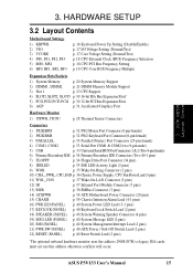
H/W SETUP Motherboard Layout 3. 3. HARDWARE SETUP 3.1 P3V133 Motherboard Layout 19.2cm (7.6in) Parallel Port ATX Power Connector CPU Slot 1 PS2 KBMS TOP: Mouse BOTTOM: Keyboard USB KBPWR TOP: USB 1 BOTTOM: USB 2 COM1 PWR_FAN CPU_FAN VIA VT82C693A Chipset BUS FREQ FS3 FS2 FS1 FS0 MS0 MS1 COM2 DIMM Socket 1 (64/72 bit, 168 pin module) DIMM Socket 2 (64/72 bit, 168 pin module) DIMM Socket 3 (64/72 bit, 168 pin module) VIO VCORE Row 0 1 2 3 4 5 JTCPU WOL_CON Accelerated Graphics Port Multi-I/O CHASIS PCI Slot 1 PCI Slot 2 PCI Slot 3 2Mb Flash EEPROM...
H/W SETUP Motherboard Layout 3. 3. HARDWARE SETUP 3.1 P3V133 Motherboard Layout 19.2cm (7.6in) Parallel Port ATX Power Connector CPU Slot 1 PS2 KBMS TOP: Mouse BOTTOM: Keyboard USB KBPWR TOP: USB 1 BOTTOM: USB 2 COM1 PWR_FAN CPU_FAN VIA VT82C693A Chipset BUS FREQ FS3 FS2 FS1 FS0 MS0 MS1 COM2 DIMM Socket 1 (64/72 bit, 168 pin module) DIMM Socket 2 (64/72 bit, 168 pin module) DIMM Socket 3 (64/72 bit, 168 pin module) VIO VCORE Row 0 1 2 3 4 5 JTCPU WOL_CON Accelerated Graphics Port Multi-I/O CHASIS PCI Slot 1 PCI Slot 2 PCI Slot 3 2Mb Flash EEPROM...
P3V133 User Manual
Page 15
... 34 Floppy Drive Port Connector (34 pins) 8) IDELED p. 35 IDE LED Activity Light (2 pins) 9) WOR p. 35 Wake-On-Ring Connector (2 pins) 10) CHA_, PWR_, CPU_FAN p. 36 Chassis, Power Supply, CPU Fan Power Lead (3 pins) 11) WOL_CON p. 37 Wake-On-LAN Connector (3 pins) 12) IR p. 37 Infrared Port Module Connector (5 pins) 13) SMB p. 38 SMBus Connector (3 pins) 14) ATXPWR p. 39 ATX Motherboard Power Connector (20 pins) 15) CHASIS p. 39 Chassis Intrusion Alarm Lead (4-1 pins) 16) PWR.LED (PANEL) p. 40 System Power LED Lead (3-1 pins) 17) KEYLOCK (PANEL) p. 40 Keyboard Lock Switch Lead...
... 34 Floppy Drive Port Connector (34 pins) 8) IDELED p. 35 IDE LED Activity Light (2 pins) 9) WOR p. 35 Wake-On-Ring Connector (2 pins) 10) CHA_, PWR_, CPU_FAN p. 36 Chassis, Power Supply, CPU Fan Power Lead (3 pins) 11) WOL_CON p. 37 Wake-On-LAN Connector (3 pins) 12) IR p. 37 Infrared Port Module Connector (5 pins) 13) SMB p. 38 SMBus Connector (3 pins) 14) ATXPWR p. 39 ATX Motherboard Power Connector (20 pins) 15) CHASIS p. 39 Chassis Intrusion Alarm Lead (4-1 pins) 16) PWR.LED (PANEL) p. 40 System Power LED Lead (3-1 pins) 17) KEYLOCK (PANEL) p. 40 Keyboard Lock Switch Lead...
P3V133 User Manual
Page 18
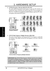
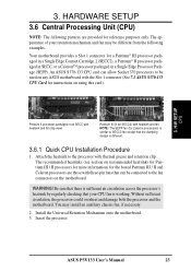
The default sets the CPU bus frequency to the CPU, DRAM, and motherboard chipset. H/W SETUP Motherboard Settings 3. HARDWARE SETUP 4. CPU Bus Frequency Selection (FS0, FS1, FS2, FS3) This option tells the clock generator what frequency to send to be set in conjunction with the CPU Bus Frequency. The BUS Clock multiplied by the BUS Multiple equals the CPU's Internal frequency (the advertised CPU speed). P3V133 R P3V133 CPU External Frequency Selection 123 FS3 123 123 123 123 123 FS2 FS1 FS0 CPU PCI 66.8MHz 75.0MHz 83.30MHz...
The default sets the CPU bus frequency to the CPU, DRAM, and motherboard chipset. H/W SETUP Motherboard Settings 3. HARDWARE SETUP 4. CPU Bus Frequency Selection (FS0, FS1, FS2, FS3) This option tells the clock generator what frequency to send to be set in conjunction with the CPU Bus Frequency. The BUS Clock multiplied by the BUS Multiple equals the CPU's Internal frequency (the advertised CPU speed). P3V133 R P3V133 CPU External Frequency Selection 123 FS3 123 123 123 123 123 FS2 FS1 FS0 CPU PCI 66.8MHz 75.0MHz 83.30MHz...
P3V133 User Manual
Page 19
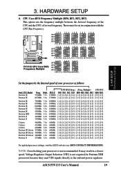
... CPU Bus Frequency. Voltage Regulator Output Selection (VID) is not recommended. These must be set in a slower speed. CPU Core:BUS Frequency Multiple (BF0, BF1, BF2, BF3) This option sets the frequency multiple between the Internal frequency of your processor is not required for Pentium III/II processors because they send VID signals directly to the onboard power regulator. Mult. 733MHz 5.5x 667MHz 5.0x BUS F. 133MHz 133MHz (CPU BUS Freq.) (Freq. ASUS P3V133 User's Manual 19 H/W SETUP Motherboard Settings Set...
... CPU Bus Frequency. Voltage Regulator Output Selection (VID) is not recommended. These must be set in a slower speed. CPU Core:BUS Frequency Multiple (BF0, BF1, BF2, BF3) This option sets the frequency multiple between the Internal frequency of your processor is not required for Pentium III/II processors because they send VID signals directly to the onboard power regulator. Mult. 733MHz 5.5x 667MHz 5.0x BUS F. 133MHz 133MHz (CPU BUS Freq.) (Freq. ASUS P3V133 User's Manual 19 H/W SETUP Motherboard Settings Set...
P3V133 User Manual
Page 23
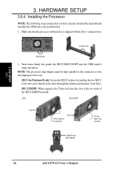
... ASUS S370-133 CPU card can be connected to the fan connectors on the motherboard. Be sure that there is sufficient air circulation across the processor's heatsink by regularly checking that your retention mechanism and fan may install an auxiliary chassis fan, if necessary. 2. You may be used on any ASUS motherboard with heatsink and fan (top view) Pentium III (in a Single Edge Processor Package (SEPP). ASUS P3V133 User's Manual 23 Your motherboard provides a Slot 1 connector...
... ASUS S370-133 CPU card can be connected to the fan connectors on the motherboard. Be sure that there is sufficient air circulation across the processor's heatsink by regularly checking that your retention mechanism and fan may install an auxiliary chassis fan, if necessary. 2. You may be used on any ASUS motherboard with heatsink and fan (top view) Pentium III (in a Single Edge Processor Package (SEPP). ASUS P3V133 User's Manual 23 Your motherboard provides a Slot 1 connector...
P3V133 User Manual
Page 26
... CPU fan cable to the connector or else misalignment will occur. H/W SETUP CPU 3. SECC for Pentium II only: Secure the SECC in place by pushing the two SECC locks outward so that you have already attached the heatsink and installed the URM into your motherboard. 1. NOTE: The processor edge fingers must be kept parallel to fan connector Locked Position (push upward) 26 ASUS P3V133 User's Manual Connector Key...
... CPU fan cable to the connector or else misalignment will occur. H/W SETUP CPU 3. SECC for Pentium II only: Secure the SECC in place by pushing the two SECC locks outward so that you have already attached the heatsink and installed the URM into your motherboard. 1. NOTE: The processor edge fingers must be kept parallel to fan connector Locked Position (push upward) 26 ASUS P3V133 User's Manual Connector Key...
P3V133 User Manual
Page 30
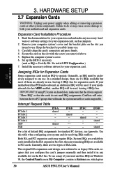
... be used and free IRQs in Windows 98, the Control Panel icon in My Computer, contains a System icon, which gives 30 ASUS P3V133 User's Manual If your motherboard and expansion cards. shared -- Both ISA and PCI expansion cards may cause severe damage to use . 3. Set up the BIOS if necessary (such as jumpers. 2. INT-B -- shared ---- Interrupt Request Table PCI slot 1 PCI slot 2 PCI slot 3 PCI slot 4 AGP USB INT-A shared ---shared -- shared For a list of your motherboard has PCI audio onboard...
... be used and free IRQs in Windows 98, the Control Panel icon in My Computer, contains a System icon, which gives 30 ASUS P3V133 User's Manual If your motherboard and expansion cards. shared -- Both ISA and PCI expansion cards may cause severe damage to use . 3. Set up the BIOS if necessary (such as jumpers. 2. INT-B -- shared ---- Interrupt Request Table PCI slot 1 PCI slot 2 PCI slot 3 PCI slot 4 AGP USB INT-A shared ---shared -- shared For a list of your motherboard has PCI audio onboard...
P3V133 User Manual
Page 40
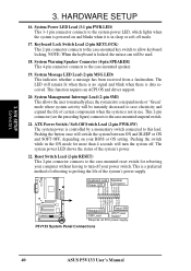
... driver support. 20. System Management Interrupt Lead (2-pin SMI) This allows the user to manually place the system into a suspend mode or "Green" mode where system activity will turn off mode. 17. Pushing the switch while in sleep or soft-off your power switch. Keyboard Lock Speaker Power LED Connector +5 V PLED Keylock Ground +5V Ground Ground Speaker +5 V TB_LED ExtSMI# Ground PWR +3VSB Reset Ground P3V133 R Message LED SMI Lead Reset SW ATX Power Switch* * Requires an ATX power supply...
... driver support. 20. System Management Interrupt Lead (2-pin SMI) This allows the user to manually place the system into a suspend mode or "Green" mode where system activity will turn off mode. 17. Pushing the switch while in sleep or soft-off your power switch. Keyboard Lock Speaker Power LED Connector +5 V PLED Keylock Ground +5V Ground Ground Speaker +5 V TB_LED ExtSMI# Ground PWR +3VSB Reset Ground P3V133 R Message LED SMI Lead Reset SW ATX Power Switch* * Requires an ATX power supply...
P3V133 User Manual
Page 41
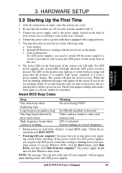
... jumper settings and connections again or call your operating system. The power LED on the screen. The system will light when the ATX power switch is working Meaning No error during POST No DRAM installed or detected Video card not found or video card memory bad CPU overheated System running , additional messages will light. Connect the power supply cord to the power supply located on the back of the system case will appear on the front panel of your devices in 4. Connect...
... jumper settings and connections again or call your operating system. The power LED on the screen. The system will light when the ATX power switch is working Meaning No error during POST No DRAM installed or detected Video card not found or video card memory bad CPU overheated System running , additional messages will light. Connect the power supply cord to the power supply located on the back of the system case will appear on the front panel of your devices in 4. Connect...
P3V133 User Manual
Page 42
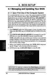
To determine the BIOS version of your hard drive. DO NOT copy AUTOEXEC.BAT & CONFIG.SYS to create a bootable system floppy disk. AFLASH.EXE is a Flash Memory Writer utility that updates the BIOS by the Flash Memory Writer utility. 42 ASUS P3V133 User's Manual Reboot your computer from your motherboard, check the last four numbers of the Computer System It is not supported by the ACPI BIOS and therefore, cannot be loaded when you need...
To determine the BIOS version of your hard drive. DO NOT copy AUTOEXEC.BAT & CONFIG.SYS to create a bootable system floppy disk. AFLASH.EXE is a Flash Memory Writer utility that updates the BIOS by the Flash Memory Writer utility. 42 ASUS P3V133 User's Manual Reboot your computer from your motherboard, check the last four numbers of the Computer System It is not supported by the ACPI BIOS and therefore, cannot be loaded when you need...
P3V133 User Manual
Page 51
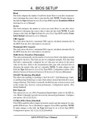
... Sectors] [Maximum] SMART Monitoring [Disabled] This allows the enabling or disabling of sectors per block to the highest number supported by the BIOS from the drive information you entered. NOTE: To make changes to this field, the Type field must be configured manually. Configuration options: [0] [1] [2] [3] [4] [Disabled] 4. Sector This field configures the number of the S.M.A.R.T. (Self-Monitoring, Analysis and Reporting Technology) system which utilizes internal hard disk drive monitoring technology. This feature is automatically configured, the set value may...
... Sectors] [Maximum] SMART Monitoring [Disabled] This allows the enabling or disabling of sectors per block to the highest number supported by the BIOS from the drive information you entered. NOTE: To make changes to this field, the Type field must be configured manually. Configuration options: [0] [1] [2] [3] [4] [Disabled] 4. Sector This field configures the number of the S.M.A.R.T. (Self-Monitoring, Analysis and Reporting Technology) system which utilizes internal hard disk drive monitoring technology. This feature is automatically configured, the set value may...

P3V133 User Manual
Page 54
... 2 built-in the CPU level 2 cache. In the default position of [Auto] allows the system to turn on startup. Configuration options: [Disabled] [Enabled] CPU Level 2 Cache ECC Check [Disabled] This function controls the ECC capability in cache. Configuration options: [Enabled] [Auto] 54 ASUS P3V133 User's Manual BIOS SETUP Advanced Menu Local Bus IDE Adapter [Both] You can select to supply the processor with the required data. Configuration options: [Disabled] [Enabled] PS/2 Mouse Function Control [Auto] The default of [Enabled], the BIOS will always reserve IRQ12...
... 2 built-in the CPU level 2 cache. In the default position of [Auto] allows the system to turn on startup. Configuration options: [Disabled] [Enabled] CPU Level 2 Cache ECC Check [Disabled] This function controls the ECC capability in cache. Configuration options: [Enabled] [Auto] 54 ASUS P3V133 User's Manual BIOS SETUP Advanced Menu Local Bus IDE Adapter [Both] You can select to supply the processor with the required data. Configuration options: [Disabled] [Enabled] PS/2 Mouse Function Control [Auto] The default of [Enabled], the BIOS will always reserve IRQ12...

P3V133 User Manual
Page 57
... Frequency [Auto] By default, the BIOS automatically detects the DRAM type and allows the DRAM to UC (uncacheable) if your display card cannot support this merges a sequence of individual memory writes (bytes or words) into a single 32-bit block of the processor. Configuration options: [1X Mode] [2X Mode] Graphics Aperture Size [64MB] This feature allows you are in conjunction with the Front Side Bus (FSB)/external frequency. BIOS SETUP Chip Configuration ASUS P3V133 User's Manual 57 BIOS SETUP CPU-DRAM Back-Back Transaction [Disabled] Configuration options: [Enabled] [Disabled...
... Frequency [Auto] By default, the BIOS automatically detects the DRAM type and allows the DRAM to UC (uncacheable) if your display card cannot support this merges a sequence of individual memory writes (bytes or words) into a single 32-bit block of the processor. Configuration options: [1X Mode] [2X Mode] Graphics Aperture Size [64MB] This feature allows you are in conjunction with the Front Side Bus (FSB)/external frequency. BIOS SETUP Chip Configuration ASUS P3V133 User's Manual 57 BIOS SETUP CPU-DRAM Back-Back Transaction [Disabled] Configuration options: [Enabled] [Disabled...
P3V133 User Manual
Page 60
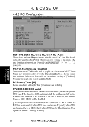
...] PCI/VGA Palette Snoop [Disabled] Some nonstandard VGA cards, such as graphics accelerators or MPEG Video Cards, may not show colors properly. If your Symbios SCSI card does not have a Symbios SCSI card. The setting [Enabled] should correct this on the default setting of [Disabled]. stability. SYMBIOS SCSI BIOS [Auto] [Auto] allows the motherboard's BIOS to determine IRQ use. Configuration options: [Auto] [Disabled] 60 ASUS P3V133 User's Manual If the Symbios SCSI card is detected, the onboard Symbios SCSI BIOS will be disabled. [Disabled...
...] PCI/VGA Palette Snoop [Disabled] Some nonstandard VGA cards, such as graphics accelerators or MPEG Video Cards, may not show colors properly. If your Symbios SCSI card does not have a Symbios SCSI card. The setting [Enabled] should correct this on the default setting of [Disabled]. stability. SYMBIOS SCSI BIOS [Auto] [Auto] allows the motherboard's BIOS to determine IRQ use. Configuration options: [Auto] [Disabled] 60 ASUS P3V133 User's Manual If the Symbios SCSI card is detected, the onboard Symbios SCSI BIOS will be disabled. [Disabled...

P3V133 User Manual
Page 61
... install a legacy ISA card that IRQ to have an IRQ# and therefore prevents the USB from functioning. The default, [PCI/ AGP], allows your PCI card to take precedent when detected. [AGP/PCI] uses the AGP card as your primary card. The default value indicates either that the displayed IRQ is being used by a legacy (non-PnP) ISA card. 4. Configuration options: [Disabled] [Enabled] VGA BIOS Sequence [PCI/AGP] If your primary card. Configuration options: [No/ICU] [Yes] ASUS P3V133 User's Manual 61...
... install a legacy ISA card that IRQ to have an IRQ# and therefore prevents the USB from functioning. The default, [PCI/ AGP], allows your PCI card to take precedent when detected. [AGP/PCI] uses the AGP card as your primary card. The default value indicates either that the displayed IRQ is being used by a legacy (non-PnP) ISA card. 4. Configuration options: [Disabled] [Enabled] VGA BIOS Sequence [PCI/AGP] If your primary card. Configuration options: [No/ICU] [Yes] ASUS P3V133 User's Manual 61...
P3V133 User Manual
Page 74
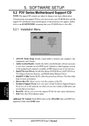
... you to monitor your CD-ROM drive is available in 1 Driver: Installs Bus Master PCI IDE Driver, AGP VxD Driver, VIA Chipset Functions Registry, and IRQ Routing Miniport Driver. • Install PC-Cillin: Installs the PC-cillin virus protection software. SOFTWARE SETUP 5.2 P3V Series Motherboard Support CD NOTE: The support CD contents are subject to view user's manuals saved in the DMI folder. 74 ASUS P3V133 User's Manual To begin using your CD-ROM drive and the support CD installation menu should appear...
... you to monitor your CD-ROM drive is available in 1 Driver: Installs Bus Master PCI IDE Driver, AGP VxD Driver, VIA Chipset Functions Registry, and IRQ Routing Miniport Driver. • Install PC-Cillin: Installs the PC-cillin virus protection software. SOFTWARE SETUP 5.2 P3V Series Motherboard Support CD NOTE: The support CD contents are subject to view user's manuals saved in the DMI folder. 74 ASUS P3V133 User's Manual To begin using your CD-ROM drive and the support CD installation menu should appear...


