P3V133 User Manual
Page 4
FEATURES 8 2.1 The ASUS P3V133 8 2.1.1 Specifications 8 2.1.2 Special Features 10 2.1.3 Performance Features 10 2.1.4 Intelligence 11 2.2 P3V133 Motherboard Components 12 3. HARDWARE SETUP 14 3.1 P3V133 Motherboard Layout 14 3.2 Layout Contents 15 3.3 Hardware Setup Steps 16 3.4 Motherboard Settings 16 3.5 System Memory (DIMM 20 3.6 Central Processing Unit (CPU 23 3.6.1 Quick CPU Installation Procedure 23 3.6.2 Attaching the Heatsink 24 3.6.3 Installing the Universal Retention Mechanism...
FEATURES 8 2.1 The ASUS P3V133 8 2.1.1 Specifications 8 2.1.2 Special Features 10 2.1.3 Performance Features 10 2.1.4 Intelligence 11 2.2 P3V133 Motherboard Components 12 3. HARDWARE SETUP 14 3.1 P3V133 Motherboard Layout 14 3.2 Layout Contents 15 3.3 Hardware Setup Steps 16 3.4 Motherboard Settings 16 3.5 System Memory (DIMM 20 3.6 Central Processing Unit (CPU 23 3.6.1 Quick CPU Installation Procedure 23 3.6.2 Attaching the Heatsink 24 3.6.3 Installing the Universal Retention Mechanism...
P3V133 User Manual
Page 5
...ASUS PC Probe 81 7. APPENDIX 87 7.1 ASUS S370-133 CPU Card 87 7.1.1 Using the ASUS S370-133 87 7.1.2 Setting up the ASUS S370-133 88 7.1.3 ASUS S370-133 Jumper Settings 88 7.2 ASUS PCI-L101 Fast Ethernet Card 89 7.2.1 Features 90 7.2.2 Software Driver Support 90 7.2.3 Questions and Answers 90 7.3 Glossary 91 ASUS P3V133... 5.1 Operating Systems 73 5.1.1 Windows 98 First Time Installation 73 5.2 P3V Series Motherboard Support CD 74 5.3 ASUS PC Probe Setup 75 5.4 Adobe Acrobat Reader 76 5.5 Install VIA 4 in 1 Driver 77 5.6 Install PC-Cillin 78 5.7 Uninstalling Programs 79...
...ASUS PC Probe 81 7. APPENDIX 87 7.1 ASUS S370-133 CPU Card 87 7.1.1 Using the ASUS S370-133 87 7.1.2 Setting up the ASUS S370-133 88 7.1.3 ASUS S370-133 Jumper Settings 88 7.2 ASUS PCI-L101 Fast Ethernet Card 89 7.2.1 Features 90 7.2.2 Software Driver Support 90 7.2.3 Questions and Answers 90 7.3 Glossary 91 ASUS P3V133... 5.1 Operating Systems 73 5.1.1 Windows 98 First Time Installation 73 5.2 P3V Series Motherboard Support CD 74 5.3 ASUS PC Probe Setup 75 5.4 Adobe Acrobat Reader 76 5.5 Install VIA 4 in 1 Driver 77 5.6 Install PC-Cillin 78 5.7 Uninstalling Programs 79...
P3V133 User Manual
Page 7
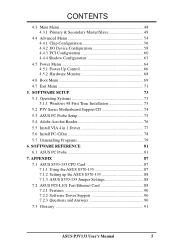
... software Reference material for the included software Optional items and general reference 1.2 Item Checklist Check that your retailer. (1) ASUS Motherboard (1) Universal Retention Mechanism for SECC2/SECC/SEPP processors (1) Ribbon cable for master and slave UltraDMA/66 or UltraDMA...(1) Support CD with drivers and utilities (1) This Motherboard User's Manual ASUS IrDA-compliant infrared module (optional) ASUS S370 Series CPU cards (optional) ASUS PCI-L101 Wake-On-LAN 10/100 Ethernet Card (optional) ASUS P3V133 User's Manual 7 INTRODUCTION 1.1 How This Manual Is Organized This manual ...
... software Reference material for the included software Optional items and general reference 1.2 Item Checklist Check that your retailer. (1) ASUS Motherboard (1) Universal Retention Mechanism for SECC2/SECC/SEPP processors (1) Ribbon cable for master and slave UltraDMA/66 or UltraDMA...(1) Support CD with drivers and utilities (1) This Motherboard User's Manual ASUS IrDA-compliant infrared module (optional) ASUS S370 Series CPU cards (optional) ASUS PCI-L101 Wake-On-LAN 10/100 Ethernet Card (optional) ASUS P3V133 User's Manual 7 INTRODUCTION 1.1 How This Manual Is Organized This manual ...
P3V133 User Manual
Page 8
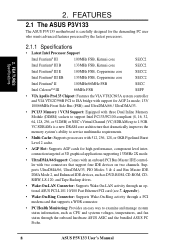
...RW, LS-120, and Tape Backup drives. • Wake-On-LAN Connector: Supports Wake-On-LAN activity through the onboard hardware ASUS ASIC and the bundled ASUS PC Probe. 8 ASUS P3V133 User's Manual Supports UltraDMA/66, UltraDMA/33, PIO Modes 3 & 4 and Bus Master IDE DMA Mode 2, and Enhanced IDE... devices, such as CPU and systerm voltages, temperatures, and fan status through an optional ASUS PCI-L101 10/100 Fast Ethernet PCI card (see...
...RW, LS-120, and Tape Backup drives. • Wake-On-LAN Connector: Supports Wake-On-LAN activity through the onboard hardware ASUS ASIC and the bundled ASUS PC Probe. 8 ASUS P3V133 User's Manual Supports UltraDMA/66, UltraDMA/33, PIO Modes 3 & 4 and Bus Master IDE DMA Mode 2, and Enhanced IDE... devices, such as CPU and systerm voltages, temperatures, and fan status through an optional ASUS PCI-L101 10/100 Fast Ethernet PCI card (see...
P3V133 User Manual
Page 9
2. ASUS P3V133 User's Manual 9 FEA TURES Specifications 2. UART2 can support Bus Master PCI cards, such as SCSI or LAN cards (PCI supports up to the memory and ... BIOS (Flash EEPROM), offering enhanced ACPI for Windows 98 compatibility, built-in a Single Edge Processor Package (SEPP). • Smart BIOS: 2MB firmware provides Vcore and CPU/SDRAM frequency adjustments, boot block write protection, and HD/SCSI/MO/ZIP/CD/Floppy boot selection. • Integrated Infrared Support: Integrated IR supports an optional...
2. ASUS P3V133 User's Manual 9 FEA TURES Specifications 2. UART2 can support Bus Master PCI cards, such as SCSI or LAN cards (PCI supports up to the memory and ... BIOS (Flash EEPROM), offering enhanced ACPI for Windows 98 compatibility, built-in a Single Edge Processor Package (SEPP). • Smart BIOS: 2MB firmware provides Vcore and CPU/SDRAM frequency adjustments, boot block write protection, and HD/SCSI/MO/ZIP/CD/Floppy boot selection. • Integrated Infrared Support: Integrated IR supports an optional...
P3V133 User Manual
Page 11
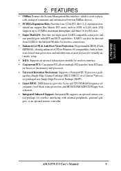
...access vital information from their limited resources more efficiently. • Temperature Monitoring and Alert: CPU temperature is in conjunction with the ASUS S370-D or S370-L CPU card) to be turned on by the ASUS ASIC through the CPU's internal thermal diode (on Pentium III, Pentium II (Deschutes), and PPGA370 Celeron in the...range and alarm thresholds. • PS/2 Keyboard/Mouse Power Up: Keyboard/Mouse Power Up can be powered on remotely through the ASUS ASIC. A chassis intrusion event is necessary to prevent possible application crashes. ASUS P3V133 User's Manual 11
...access vital information from their limited resources more efficiently. • Temperature Monitoring and Alert: CPU temperature is in conjunction with the ASUS S370-D or S370-L CPU card) to be turned on by the ASUS ASIC through the CPU's internal thermal diode (on Pentium III, Pentium II (Deschutes), and PPGA370 Celeron in the...range and alarm thresholds. • PS/2 Keyboard/Mouse Power Up: Keyboard/Mouse Power Up can be powered on remotely through the ASUS ASIC. A chassis intrusion event is necessary to prevent possible application crashes. ASUS P3V133 User's Manual 11

P3V133 User Manual
Page 14
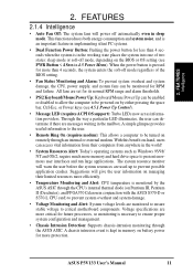
HARDWARE SETUP 3.1 P3V133 Motherboard Layout 19.2cm (7.6in) Parallel Port ATX Power Connector CPU Slot 1 PS2 KBMS TOP: Mouse BOTTOM: Keyboard USB KBPWR TOP: USB 1 BOTTOM: USB 2 COM1 PWR_FAN CPU_FAN VIA VT82C693A Chipset BUS FREQ FS3 FS2 FS1 ... JTPWR Hardware Monitor SMB PCI Slot 4 ISA Slot 1 P3V133 R ISA Slot 2 ISA Slot 3 CR2032 3V Lithium Cell (CMOS Power) CHA_FAN CLRTC VIA VT82C596B PCIset WOR BF3 BF2 BF1 BF0 FREQ MULT ASUS ASIC IR IDE LED PANEL FLOPPY SECONDARY IDE PRIMARY IDE 30.5cm (12.0in) 14 ASUS P3V133 User's Manual 3. H/W SETUP Motherboard Layout 3.
HARDWARE SETUP 3.1 P3V133 Motherboard Layout 19.2cm (7.6in) Parallel Port ATX Power Connector CPU Slot 1 PS2 KBMS TOP: Mouse BOTTOM: Keyboard USB KBPWR TOP: USB 1 BOTTOM: USB 2 COM1 PWR_FAN CPU_FAN VIA VT82C693A Chipset BUS FREQ FS3 FS2 FS1 ... JTPWR Hardware Monitor SMB PCI Slot 4 ISA Slot 1 P3V133 R ISA Slot 2 ISA Slot 3 CR2032 3V Lithium Cell (CMOS Power) CHA_FAN CLRTC VIA VT82C596B PCIset WOR BF3 BF2 BF1 BF0 FREQ MULT ASUS ASIC IR IDE LED PANEL FLOPPY SECONDARY IDE PRIMARY IDE 30.5cm (12.0in) 14 ASUS P3V133 User's Manual 3. H/W SETUP Motherboard Layout 3.
P3V133 User Manual
Page 15
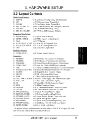
... Connector (34 pins) 8) IDELED p. 35 IDE LED Activity Light (2 pins) 9) WOR p. 35 Wake-On-Ring Connector (2 pins) 10) CHA_, PWR_, CPU_FAN p. 36 Chassis, Power Supply, CPU Fan Power Lead (3 pins) 11) WOL_CON p. 37 Wake-On-LAN Connector (3 pins) 12) IR p. 37 Infrared Port Module Connector (5 pins) 13) SMB p. 38 SMBus Connector... Lead (2 pins) *The optional onboard hardware monitor uses the address 290H-297H so legacy ISA cards must not use this address otherwise conflicts will occur. ASUS P3V133 User's Manual 15 3. H/W SETUP Layout Contents 3.
... Connector (34 pins) 8) IDELED p. 35 IDE LED Activity Light (2 pins) 9) WOR p. 35 Wake-On-Ring Connector (2 pins) 10) CHA_, PWR_, CPU_FAN p. 36 Chassis, Power Supply, CPU Fan Power Lead (3 pins) 11) WOL_CON p. 37 Wake-On-LAN Connector (3 pins) 12) IR p. 37 Infrared Port Module Connector (5 pins) 13) SMB p. 38 SMBus Connector... Lead (2 pins) *The optional onboard hardware monitor uses the address 290H-297H so legacy ISA cards must not use this address otherwise conflicts will occur. ASUS P3V133 User's Manual 15 3. H/W SETUP Layout Contents 3.
P3V133 User Manual
Page 16
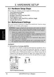
Install Memory Modules 3. Install the Central Processing Unit (CPU) 4. Connect Ribbon Cables, Panel Wires, and Power Supply 6. To protect them against damage from the system. If you do not have the right ATX... your computer. 1. Check Motherboard Settings 2. Unplug your keyboard (by the edges and try not to power up function. KBPWR 3 2 1 Disable (Default) 3 2 1 Enable P3V133 R P3V133 Keyboard Power Up 16 ASUS P3V133 User's Manual Install Expansion Cards 5. Hold components by pressing ) to touch the IC chips, leads or connectors, or other components. 4. Use a grounded wrist...
Install Memory Modules 3. Install the Central Processing Unit (CPU) 4. Connect Ribbon Cables, Panel Wires, and Power Supply 6. To protect them against damage from the system. If you do not have the right ATX... your computer. 1. Check Motherboard Settings 2. Unplug your keyboard (by the edges and try not to power up function. KBPWR 3 2 1 Disable (Default) 3 2 1 Enable P3V133 R P3V133 Keyboard Power Up 16 ASUS P3V133 User's Manual Install Expansion Cards 5. Hold components by pressing ) to touch the IC chips, leads or connectors, or other components. 4. Use a grounded wrist...
P3V133 User Manual
Page 17
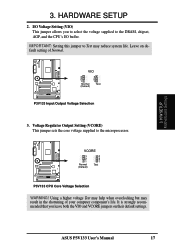
.... IMPORTANT: Setting this jumper to Test may result in the shortening of Normal. VCORE 3 2 1 Normal (Default) 3 2 1 Test P3V133 R P3V133 CPU Core Voltage Selection WARNING! ASUS P3V133 User's Manual 17 3. P3V133 R VIO 3 2 1 Normal (Default) 3 2 1 Test P3V133 Input/Output Voltage Selection 3. I/O Voltage Setting (VIO) This jumper allows you leave both the VIO and VCORE jumpers on default... settings. H/W SETUP Motherboard Settings 3. Voltage Regulator Output Setting (VCORE) This jumper sets the core voltage supplied to the DRAM, chipset, AGP, and the CPU's I/O buffer.
.... IMPORTANT: Setting this jumper to Test may result in the shortening of Normal. VCORE 3 2 1 Normal (Default) 3 2 1 Test P3V133 R P3V133 CPU Core Voltage Selection WARNING! ASUS P3V133 User's Manual 17 3. P3V133 R VIO 3 2 1 Normal (Default) 3 2 1 Test P3V133 Input/Output Voltage Selection 3. I/O Voltage Setting (VIO) This jumper allows you leave both the VIO and VCORE jumpers on default... settings. H/W SETUP Motherboard Settings 3. Voltage Regulator Output Setting (VCORE) This jumper sets the core voltage supplied to the DRAM, chipset, AGP, and the CPU's I/O buffer.
P3V133 User Manual
Page 18
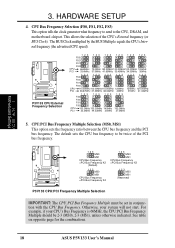
...option sets the frequency ratio between the CPU bus frequency and the PCI bus frequency. See table on opposite page for the combinations. 18 ASUS P3V133 User's Manual P3V133 R 123 MS0 MS1 CPU Bus Frequency =PCI Bus Frequency X2 (Default) 123 MS0 MS1 CPU Bus Frequency =PCI Bus Frequency X4... 123 MS0 MS1 CPU Bus Frequency =PCI Bus Frequency X3 123 MS0 MS1 (Reserved) P3V133 CPU:PCI Frequency Multiple Selection IMPORTANT: The CPU:PCI ...
...option sets the frequency ratio between the CPU bus frequency and the PCI bus frequency. See table on opposite page for the combinations. 18 ASUS P3V133 User's Manual P3V133 R 123 MS0 MS1 CPU Bus Frequency =PCI Bus Frequency X2 (Default) 123 MS0 MS1 CPU Bus Frequency =PCI Bus Frequency X4... 123 MS0 MS1 CPU Bus Frequency =PCI Bus Frequency X3 123 MS0 MS1 (Reserved) P3V133 CPU:PCI Frequency Multiple Selection IMPORTANT: The CPU:PCI ...
P3V133 User Manual
Page 19
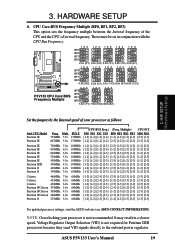
... the onboard power regulator. Mult. 733MHz 5.5x 667MHz 5.0x BUS F. 133MHz 133MHz (CPU BUS Freq.) (Freq. Voltage Regulator Output Selection (VID) is not recommended. ASUS P3V133 User's Manual 19 HARDWARE SETUP 6. It may result in conjunction with the CPU Bus Frequency. Multiple) CPU:PCI FS0 FS1 FS2 FS3 BF0 BF1 BF2 BF3 MS0 MS1 [1-2] [1-2] [1-2] [1-2] [1-2] [1-2] [1-2] [2-3] [2-3] [1-2] [1-2] [1-2] [1-2] [1-2] [2-3] [1-2] [1-2] [2-3] [2-3] [1-2] Pentium...
... the onboard power regulator. Mult. 733MHz 5.5x 667MHz 5.0x BUS F. 133MHz 133MHz (CPU BUS Freq.) (Freq. Voltage Regulator Output Selection (VID) is not recommended. ASUS P3V133 User's Manual 19 HARDWARE SETUP 6. It may result in conjunction with the CPU Bus Frequency. Multiple) CPU:PCI FS0 FS1 FS2 FS3 BF0 BF1 BF2 BF3 MS0 MS1 [1-2] [1-2] [1-2] [1-2] [1-2] [1-2] [1-2] [2-3] [2-3] [1-2] [1-2] [1-2] [1-2] [1-2] [2-3] [1-2] [1-2] [2-3] [2-3] [1-2] Pentium...
P3V133 User Manual
Page 20
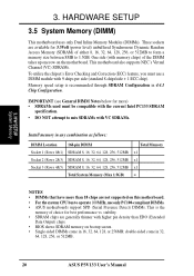
... support SPD (Serial Presence Detect) DIMMs. This is recommended through SDRAM Configuration in 32, 64, 128, 256, or 512MB. 20 ASUS P3V133 User's Manual Three sockets are available for best performance vs. double-sided come in 16, 32, 64, 128, or 256MB; HARDWARE SETUP 3.5 System Memory (DIMM) ... for 3.3Volt (power level) unbuffered Synchronous Dynamic Random Access Memory (SDRAM) of the DIMM takes up one row on this motherboard. • For the system CPU bus to 1.5GB. H/W SETUP System Memory 3.
... support SPD (Serial Presence Detect) DIMMs. This is recommended through SDRAM Configuration in 32, 64, 128, 256, or 512MB. 20 ASUS P3V133 User's Manual Three sockets are available for best performance vs. double-sided come in 16, 32, 64, 128, or 256MB; HARDWARE SETUP 3.5 System Memory (DIMM) ... for 3.3Volt (power level) unbuffered Synchronous Dynamic Random Access Memory (SDRAM) of the DIMM takes up one row on this motherboard. • For the system CPU bus to 1.5GB. H/W SETUP System Memory 3.
P3V133 User Manual
Page 23
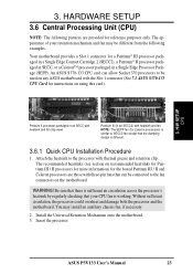
... on using this card). 3. Without sufficient circulation, the processor could overheat and damage both the processor and the motherboard. ASUS P3V133 User's Manual 23 H/W SETUP CPU Pentium II processor packaged in an SECC with heatsink and fan (top view) Pentium III (in a Single Edge Processor ... that the clamping design is working. An ASUS S370-133 CPU card can be connected to the processor with the Slot 1 connector (See 7.1 ASUS S370-133 CPU Card for instructions on the motherboard. You may be used on any ASUS motherboard with thermal grease and retention clip. ...
... on using this card). 3. Without sufficient circulation, the processor could overheat and damage both the processor and the motherboard. ASUS P3V133 User's Manual 23 H/W SETUP CPU Pentium II processor packaged in an SECC with heatsink and fan (top view) Pentium III (in a Single Edge Processor ... that the clamping design is working. An ASUS S370-133 CPU card can be connected to the processor with the Slot 1 connector (See 7.1 ASUS S370-133 CPU Card for instructions on the motherboard. You may be used on any ASUS motherboard with thermal grease and retention clip. ...

P3V133 User Manual
Page 24
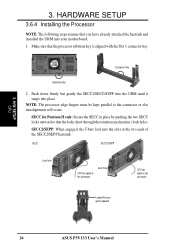
H/W SETUP CPU 3. HARDWARE SETUP 3.6.2 Attaching the Heatsink NOTE: If provided, you should follow the heatsink attachment instructions that the clamping design is different. Four Pins and metal ... direction to the processor package. 3. Mount the heatsink to release. Attach the heatsink to provide adequate circulation across the processor's passive heatsink. 24 ASUS P3V133 User's Manual otherwise, the CPU will overheat. The following steps are provided only as a general guide and may install an auxiliary fan to the processor core with Pentium...
H/W SETUP CPU 3. HARDWARE SETUP 3.6.2 Attaching the Heatsink NOTE: If provided, you should follow the heatsink attachment instructions that the clamping design is different. Four Pins and metal ... direction to the processor package. 3. Mount the heatsink to release. Attach the heatsink to provide adequate circulation across the processor's passive heatsink. 24 ASUS P3V133 User's Manual otherwise, the CPU will overheat. The following steps are provided only as a general guide and may install an auxiliary fan to the processor core with Pentium...
P3V133 User Manual
Page 25
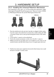
HARDWARE SETUP 3.6.3 Installing the Universal Retention Mechanism Your motherboard comes with the motherboard. H/W SETUP CPU ASUS P3V133 User's Manual 25 There are not pushed in, press down into the black fastener sleeves until the black fastener sleeves fit snugly against the board. 5. ...
HARDWARE SETUP 3.6.3 Installing the Universal Retention Mechanism Your motherboard comes with the motherboard. H/W SETUP CPU ASUS P3V133 User's Manual 25 There are not pushed in, press down into the black fastener sleeves until the black fastener sleeves fit snugly against the board. 5. ...
P3V133 User Manual
Page 26
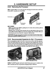
... sure that you have already attached the heatsink and installed the URM into your motherboard. 1. SECC SECC2/SEPP Lock hole CPU fan cable to fan connector Lock hole CPU fan cable to the connector or else misalignment will occur. SECC for Pentium II only: Secure the SECC in place by...the T-bars lock into place. 3. NOTE: The processor edge fingers must be kept parallel to fan connector Locked Position (push upward) 26 ASUS P3V133 User's Manual H/W SETUP CPU 3. Push down firmly but gently the SECC2/SECC/SEPP into the URM until it snaps into the slots at the two ends of the...
... sure that you have already attached the heatsink and installed the URM into your motherboard. 1. SECC SECC2/SEPP Lock hole CPU fan cable to fan connector Lock hole CPU fan cable to the connector or else misalignment will occur. SECC for Pentium II only: Secure the SECC in place by...the T-bars lock into place. 3. NOTE: The processor edge fingers must be kept parallel to fan connector Locked Position (push upward) 26 ASUS P3V133 User's Manual H/W SETUP CPU 3. Push down firmly but gently the SECC2/SECC/SEPP into the URM until it snaps into the slots at the two ends of the...
P3V133 User Manual
Page 27
.... You may wear gloves to disengage the latch feature and firmly lift the SECC assembly out of the slot 1 connector with your other . ASUS P3V133 User's Manual 27 URM (B): Place one hand on the heatsink and your thumb while you rotate the processor out of the URM. These heatsinks... pushing the two locks down and then pull the SECC2/SEPP assembly out. SECC2/SEPP Push lock inward CPU fan cable to fan connector CPU fan cable to the motherboard's CPU fan connector. 3. H/W SETUP CPU SECC Heatsink & Fan SECC2 Heatsink & Fan NOTE: The SEPP heatsink and fan (for the Slot 1...
.... You may wear gloves to disengage the latch feature and firmly lift the SECC assembly out of the slot 1 connector with your other . ASUS P3V133 User's Manual 27 URM (B): Place one hand on the heatsink and your thumb while you rotate the processor out of the URM. These heatsinks... pushing the two locks down and then pull the SECC2/SEPP assembly out. SECC2/SEPP Push lock inward CPU fan cable to fan connector CPU fan cable to the motherboard's CPU fan connector. 3. H/W SETUP CPU SECC Heatsink & Fan SECC2 Heatsink & Fan NOTE: The SEPP heatsink and fan (for the Slot 1...
P3V133 User Manual
Page 28
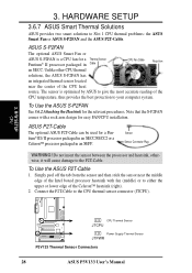
...-Cable to Slot 1 CPU thermal problems: the ASUS Smart Fan or ASUS S-P2FAN and the ASUS P2T-Cable. HARDWARE SETUP 3.6.7 ASUS Smart Thermal Solutions ASUS provides two smart solutions to the CPU thermal sensor connector (JTCPU). 3. H/W SETUP CPU CPU Thermal Sensor JTCPU P3V133 R Power Supply Thermal Sensor JTPWR P3V133 Thermal Sensor Connectors 28 ASUS P3V133 User's Manual To Use the ASUS S-P2FAN See 3.6.2 Attaching...
...-Cable to Slot 1 CPU thermal problems: the ASUS Smart Fan or ASUS S-P2FAN and the ASUS P2T-Cable. HARDWARE SETUP 3.6.7 ASUS Smart Thermal Solutions ASUS provides two smart solutions to the CPU thermal sensor connector (JTCPU). 3. H/W SETUP CPU CPU Thermal Sensor JTCPU P3V133 R Power Supply Thermal Sensor JTPWR P3V133 Thermal Sensor Connectors 28 ASUS P3V133 User's Manual To Use the ASUS S-P2FAN See 3.6.2 Attaching...

P3V133 User Manual
Page 29
...If, however, the BIOS and/or your hardware monitoring program is no through-holes or debris. There is reporting a CPU temperature above its maximum specified operating temperature will shorten the processor lifetime and may be continuous with a strong retention clip... is connected to have accurate temperature readings of the processor core (the main source of an incorrectly installed retention clip 3. H/W SETUP CPU ASUS P3V133 User's Manual 29 Included inside Pentium III, Pentium II (Deschutes), FCPGA370 Celeron, and PPGA370 Celeron processors is a thermal sensor that take...
...If, however, the BIOS and/or your hardware monitoring program is no through-holes or debris. There is reporting a CPU temperature above its maximum specified operating temperature will shorten the processor lifetime and may be continuous with a strong retention clip... is connected to have accurate temperature readings of the processor core (the main source of an incorrectly installed retention clip 3. H/W SETUP CPU ASUS P3V133 User's Manual 29 Included inside Pentium III, Pentium II (Deschutes), FCPGA370 Celeron, and PPGA370 Celeron processors is a thermal sensor that take...


