User Manual
Page 1
R P/I-P55TVP4 Pentium Motherboard USER'S MANUAL
R P/I-P55TVP4 Pentium Motherboard USER'S MANUAL
User Manual
Page 4
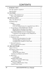
... 26 Flash Memory Writer Utility 26 Main Menu 26 Advanced Features Menu 27 Updating your Motherboard's BIOS 28 6. CONTENTS I -P55TVP4 User's Manual INSTALLATION 4 Map of BIOS Features Setup 34 Chipset Features Setup 37 IV ASUS P/I . Expansion Cards 16 Expansion Card Installation Procedure 16 Assigning IRQs for Expansion Cards... 29 Load Defaults 30 Standard CMOS Setup 30 Details of Standard CMOS Setup 31 BIOS Features Setup 34 Details of the Motherboard 4 Installation Steps 6 1. External Connectors 19 Power Connection Procedures 25 IV. FEATURES 2 Features of This...
... 26 Flash Memory Writer Utility 26 Main Menu 26 Advanced Features Menu 27 Updating your Motherboard's BIOS 28 6. CONTENTS I -P55TVP4 User's Manual INSTALLATION 4 Map of BIOS Features Setup 34 Chipset Features Setup 37 IV ASUS P/I . Expansion Cards 16 Expansion Card Installation Procedure 16 Assigning IRQs for Expansion Cards... 29 Load Defaults 30 Standard CMOS Setup 30 Details of Standard CMOS Setup 31 BIOS Features Setup 34 Details of the Motherboard 4 Installation Steps 6 1. External Connectors 19 Power Connection Procedures 25 IV. FEATURES 2 Features of This...

User Manual
Page 7
...-SC200: Installation of an optional 16-bit Audio card VIII. Windows 95: Audio Software Manual (with ASUS I -P55TVP4 User's Manual 1 If you discover damaged or missing items, please contact your retailer. √ The ASUS P/I-P55TVP4 motherboard √ 2 serial port ribbon cables attached to a mounting bracket √ 1 parallel ribbon cable with mounting bracket √ 1 IDE ribbon...
...-SC200: Installation of an optional 16-bit Audio card VIII. Windows 95: Audio Software Manual (with ASUS I -P55TVP4 User's Manual 1 If you discover damaged or missing items, please contact your retailer. √ The ASUS P/I-P55TVP4 motherboard √ 2 serial port ribbon cables attached to a mounting bracket √ 1 parallel ribbon cable with mounting bracket √ 1 IDE ribbon...

User Manual
Page 8
... three 32-bit PCI slots, and one parallel port with PCI Slot 4 for an optional high-performance expansion card which allows the use of This Motherboard The P/I /O subsystems. • Desktop Management Interface (DMI): Supports DMI through a Synchronous SRAM cache module. (See page 14 for compatible cache... and CD-ROM drives. UART2 can also be directed from COM2 to -install card. • Super Multi-I -P55TVP4 User's Manual BIOS supports IDE CD-ROM boot-up. 2 ASUS P/I /O: Provides two high-speed UART compatible serial ports and one PCI/MediaBus 2.0 which includes two functions in 0KB...
... three 32-bit PCI slots, and one parallel port with PCI Slot 4 for an optional high-performance expansion card which allows the use of This Motherboard The P/I /O subsystems. • Desktop Management Interface (DMI): Supports DMI through a Synchronous SRAM cache module. (See page 14 for compatible cache... and CD-ROM drives. UART2 can also be directed from COM2 to -install card. • Super Multi-I -P55TVP4 User's Manual BIOS supports IDE CD-ROM boot-up. 2 ASUS P/I /O: Provides two high-speed UART compatible serial ports and one PCI/MediaBus 2.0 which includes two functions in 0KB...
User Manual
Page 9
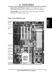
... 7 L2 Upgrade Cache Expansion Slot Onboard 256KB/ 512KB Pipelined Burst L2 Cache ASUS P/I /O 1 DIMM Slot II. FEATURES (Parts of the Motherboard Programmable Flash ROM 3 ISA Slots 3 PCI Slots Super Multi-I -P55TVP4 User's Manual 3 FEATURES • Optional IrDA and PS/2 Mouse Connector: This motherboard supports an optional infrared port module for wireless interface and a PS...
... 7 L2 Upgrade Cache Expansion Slot Onboard 256KB/ 512KB Pipelined Burst L2 Cache ASUS P/I /O 1 DIMM Slot II. FEATURES (Parts of the Motherboard Programmable Flash ROM 3 ISA Slots 3 PCI Slots Super Multi-I -P55TVP4 User's Manual 3 FEATURES • Optional IrDA and PS/2 Mouse Connector: This motherboard supports an optional infrared port module for wireless interface and a PS...
User Manual
Page 10
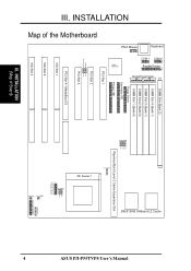
...Map of the Motherboard PS/2 Mouse Keyboard COM 1 COM 2 Parallel Printer P9 Board Power Input P8 DIMM Slot (Bank 2) SIMM Slot 4 (Bank 1) SIMM Slot 3 (Bank 1) SIMM Slot 2 (Bank 0) SIMM Slot 1 (Bank 0) Floppy Drives Secondary IDE Primary IDE PCI Slot 1 Super Multi I/O PCI Slot 2 Multi I -P55TVP4 User's Manual III.... Case Conn (CON 1) Vio/Vcore JP22 JP21 JP20 JP19 JP18 JP17 JP16 BUS Ratio IDE LED Clear CMOS JP7 256/512KB OnBoard L2 Cache 4 ASUS P/I /O Boot Program JP9 JP10 PCI Slot 3 PCI Slot 4 /...
...Map of the Motherboard PS/2 Mouse Keyboard COM 1 COM 2 Parallel Printer P9 Board Power Input P8 DIMM Slot (Bank 2) SIMM Slot 4 (Bank 1) SIMM Slot 3 (Bank 1) SIMM Slot 2 (Bank 0) SIMM Slot 1 (Bank 0) Floppy Drives Secondary IDE Primary IDE PCI Slot 1 Super Multi I/O PCI Slot 2 Multi I -P55TVP4 User's Manual III.... Case Conn (CON 1) Vio/Vcore JP22 JP21 JP20 JP19 JP18 JP17 JP16 BUS Ratio IDE LED Clear CMOS JP7 256/512KB OnBoard L2 Cache 4 ASUS P/I /O Boot Program JP9 JP10 PCI Slot 3 PCI Slot 4 /...

User Manual
Page 11
... Motherboard Power Connector (12-pin Block) p. 22 Primary / Secondary IDE Connector (40-pin Blocks) p. 22 IDE LED Activity Light p. 23 Turbo LED/Power LED (2-pins) p. 23 SMI Switch Lead (2-pins) p. 23 Reset Switch Lead (2-pins) p. 23 Keyboard Lock Switch Lead (5-pins) p. 23 Speaker Output Connector (4-pins) p. 24 Infrared Port Module Connector ASUS P/I-P55TVP4...
... Motherboard Power Connector (12-pin Block) p. 22 Primary / Secondary IDE Connector (40-pin Blocks) p. 22 IDE LED Activity Light p. 23 Turbo LED/Power LED (2-pins) p. 23 SMI Switch Lead (2-pins) p. 23 Reset Switch Lead (2-pins) p. 23 Keyboard Lock Switch Lead (5-pins) p. 23 Speaker Output Connector (4-pins) p. 24 Infrared Port Module Connector ASUS P/I-P55TVP4...
User Manual
Page 12
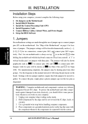
.... Use the diagrams in this manual instead of the Motherboard" on jumpers with two jumper numbers require that came with the keyboard connector away from other components against damage from the system. 6 ASUS P/I-P55TVP4 User's Manual To connect the pins, simply place a... plastic jumper cap over the two pins as to connect pins 1&2 and to connect pins 2&3. To protect the motherboard and other groups. See "Map of following steps: 1. ...
.... Use the diagrams in this manual instead of the Motherboard" on jumpers with two jumper numbers require that came with the keyboard connector away from other components against damage from the system. 6 ASUS P/I-P55TVP4 User's Manual To connect the pins, simply place a... plastic jumper cap over the two pins as to connect pins 1&2 and to connect pins 2&3. To protect the motherboard and other groups. See "Map of following steps: 1. ...
User Manual
Page 14
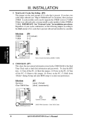
... the CMOS RAM of Motherboard" for installation procedures. If you may install a cache module of L2 cache that is no onboard cache, you have 256KB. Selections Operation Clear CMOS Data JP7 [open] (Default) [short] (momentarily) JP7 Operation (Default) JP7 Clear Data CMOS RAM (Operation / Clear CMOS Data) 8 ASUS P/I-P55TVP4 User's Manual INSTALLATION 3. If...
... the CMOS RAM of Motherboard" for installation procedures. If you may install a cache module of L2 cache that is no onboard cache, you have 256KB. Selections Operation Clear CMOS Data JP7 [open] (Default) [short] (momentarily) JP7 Operation (Default) JP7 Clear Data CMOS RAM (Operation / Clear CMOS Data) 8 ASUS P/I-P55TVP4 User's Manual INSTALLATION 3. If...
User Manual
Page 15
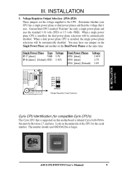
... CPU is installed, the dual power plane selections will be Revision 2.7 and later. Look on this motherboard is supported on the underside of the CPU for compatible Cyrix CPU's) The Cyrix CPU that it uses. ASUS P/I-P55TVP4 User's Manual 9 The number should read G8DC6620A or larger. Single Power Plane Type Voltage JP17 [short...
... CPU is installed, the dual power plane selections will be Revision 2.7 and later. Look on this motherboard is supported on the underside of the CPU for compatible Cyrix CPU's) The Cyrix CPU that it uses. ASUS P/I-P55TVP4 User's Manual 9 The number should read G8DC6620A or larger. Single Power Plane Type Voltage JP17 [short...
User Manual
Page 16
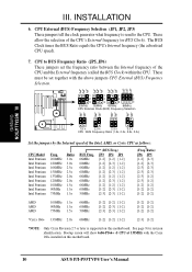
... to BUS Frequency Ratio (JP5, JP6) These jumpers set together with the Cyrix 166+ installed on this motherboard. 10 ASUS P/I-P55TVP4 User's Manual Bootup screen will show 6x86-P166+ -S CPU at 133MHz with the above jumpers CPU External ...[2-3] [1-2] [2-3] [2-3] [1-2] [1-2] [1-2] [1-2] [1-2] [1-2] [1-2] *Cyrix 166+ 133MHz 2.0x 66MHz [1-2] [1-2] [1-2] [2-3] [1-2] *NOTE: Only Cyrix Revision 2.7 or later is supported on this motherboard. These must be set the frequency ratio between the Internal frequency of the CPU and the External frequency (called the BUS Clock) within the CPU...
... to BUS Frequency Ratio (JP5, JP6) These jumpers set together with the Cyrix 166+ installed on this motherboard. 10 ASUS P/I-P55TVP4 User's Manual Bootup screen will show 6x86-P166+ -S CPU at 133MHz with the above jumpers CPU External ...[2-3] [1-2] [2-3] [2-3] [1-2] [1-2] [1-2] [1-2] [1-2] [1-2] [1-2] *Cyrix 166+ 133MHz 2.0x 66MHz [1-2] [1-2] [1-2] [2-3] [1-2] *NOTE: Only Cyrix Revision 2.7 or later is supported on this motherboard. These must be set the frequency ratio between the Internal frequency of the CPU and the External frequency (called the BUS Clock) within the CPU...
User Manual
Page 17
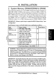
... 1 Double sided memory module. Install memory in BIOS Chipset Setup "Auto Configuration." The SDRAM that each bank contains two of Banks 1 & 2. Related ASUS P/I-P55TVP4 User's Manual 11 The DRAM can be empty) Bank 2 8MB, 16MB, 32MB, 64MB x1 DIMM Slot 1 168-pin Synchronous DIMM (Single sided; ...so that you may be unstable. Modules with more than 24 chips per module. INSTALLATION 2. System Memory (DRAM/SDRAM & SRAM) This motherboard supports four 72-pin SIMMs (Single Inline Memory Modules) of the banks in the Bank 2 DIMM slot must have two sides, either ...
... 1 Double sided memory module. Install memory in BIOS Chipset Setup "Auto Configuration." The SDRAM that each bank contains two of Banks 1 & 2. Related ASUS P/I-P55TVP4 User's Manual 11 The DRAM can be empty) Bank 2 8MB, 16MB, 32MB, 64MB x1 DIMM Slot 1 168-pin Synchronous DIMM (Single sided; ...so that you may be unstable. Modules with more than 24 chips per module. INSTALLATION 2. System Memory (DRAM/SDRAM & SRAM) This motherboard supports four 72-pin SIMMs (Single Inline Memory Modules) of the banks in the Bank 2 DIMM slot must have two sides, either ...
User Manual
Page 19
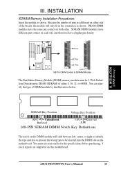
...shown. You must be inserted into the DIMM slot on both sides. ASUS P/I-P55TVP4 User's Manual 13 SDRAM DIMM modules have different pint contact on each side and therefore have the same pin contact on the motherboard. DRAM SIMM modules have a higher pin density. 88 Pins 60 ...The Dual Inline Memory Module (DIMM) memory module must ask your retailer for the specifications before purchasing. 4 clock signals are different on this motherboard. You can identify the type of pins are supported on either side of either 8, 16, 32, or 64MB. INSTALLATION SDRAM Memory Installation ...
...shown. You must be inserted into the DIMM slot on both sides. ASUS P/I-P55TVP4 User's Manual 13 SDRAM DIMM modules have different pint contact on each side and therefore have the same pin contact on the motherboard. DRAM SIMM modules have a higher pin density. 88 Pins 60 ...The Dual Inline Memory Module (DIMM) memory module must ask your retailer for the specifications before purchasing. 4 clock signals are different on this motherboard. You can identify the type of pins are supported on either side of either 8, 16, 32, or 64MB. INSTALLATION SDRAM Memory Installation ...
User Manual
Page 20
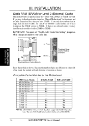
... "COAST" cache module can be used to upgrade the 256KB version to comply with the onboard TAG SRAM. 14 ASUS P/I-P55TVP4 User's Manual IMPORTANT: You must set "Total Level 2 Cache Size Setting" jumper on when changes are different on either side ... 512KB. This extra TAG SRAM will only fit in the orientation as shown. III. INSTALLATION Static RAM (SRAM) for this Motherboard SIMM Cache Module ASUS CM1 Rev 1.0 ASUS CM1 Rev 1.3 ASUS CM4 Rev 1.5 ASUS CM1 Rev 1.6 ASUS CM1 Rev 3.0* COAST 1.1 COAST 1.2 COAST 1.3 COAST 2.0 COAST 2.1 COAST 3.0 COAST 3.1 256KB to 512KB ---------Yes Yes ...
... "COAST" cache module can be used to upgrade the 256KB version to comply with the onboard TAG SRAM. 14 ASUS P/I-P55TVP4 User's Manual IMPORTANT: You must set "Total Level 2 Cache Size Setting" jumper on when changes are different on either side ... 512KB. This extra TAG SRAM will only fit in the orientation as shown. III. INSTALLATION Static RAM (SRAM) for this Motherboard SIMM Cache Module ASUS CM1 Rev 1.0 ASUS CM1 Rev 1.3 ASUS CM4 Rev 1.5 ASUS CM1 Rev 1.6 ASUS CM1 Rev 3.0* COAST 1.1 COAST 1.2 COAST 1.3 COAST 2.0 COAST 2.1 COAST 3.0 COAST 3.1 256KB to 512KB ---------Yes Yes ...
User Manual
Page 21
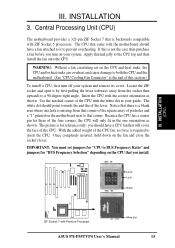
...correct orientation as your system. Apply thermal jelly to insert the CPU. Insert the CPU with ZIF Socket 5 processors. Notice that came with the motherboard should have a CPU fan that is a blank area where one orientation as shown. Lever Lock Blank ZIF Socket 7 with the white dot as...CPU that you should point towards the end the of the CPU with Pentium Processor White Dot ASUS P/I-P55TVP4 User's Manual 15 Use the notched corner of the lever. Central Processing Unit (CPU) The motherboard provides a 321-pin ZIF Socket 7 that will only fit in the one hole is for ...
...correct orientation as your system. Apply thermal jelly to insert the CPU. Insert the CPU with ZIF Socket 5 processors. Notice that came with the motherboard should have a CPU fan that is a blank area where one orientation as shown. Lever Lock Blank ZIF Socket 7 with the white dot as...CPU that you should point towards the end the of the CPU with Pentium Processor White Dot ASUS P/I-P55TVP4 User's Manual 15 Use the notched corner of the lever. Central Processing Unit (CPU) The motherboard provides a 321-pin ZIF Socket 7 that will only fit in the one hole is for ...
User Manual
Page 22
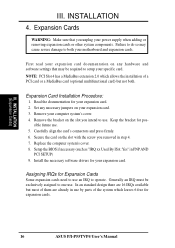
...may be exclusively assigned to both . NOTE: PCI Slot 4 has a MediaBus extension 2.0 which leaves 6 free for expansion cards. 16 ASUS P/I-P55TVP4 User's Manual Expansion Card Installation Procedure: 1. Assigning IRQs for your computer system's cover. 4. Expansion Cards WARNING: Make sure that may cause.... 2. Remove your expansion card. Remove the bracket on your expansion card documentation on the slot with the screw you unplug your motherboard and expansion cards. Replace the computer system's cover. 8. Setup the BIOS if necessary (such as "IRQ xx Used By ISA...
...may be exclusively assigned to both . NOTE: PCI Slot 4 has a MediaBus extension 2.0 which leaves 6 free for expansion cards. 16 ASUS P/I-P55TVP4 User's Manual Expansion Card Installation Procedure: 1. Assigning IRQs for your computer system's cover. 4. Expansion Cards WARNING: Make sure that may cause.... 2. Remove your expansion card. Remove the bracket on your expansion card documentation on the slot with the screw you unplug your motherboard and expansion cards. Replace the computer system's cover. 8. Setup the BIOS if necessary (such as "IRQ xx Used By ISA...
User Manual
Page 23
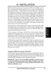
...on your vendor for an ISA Configuration Utility. For older Legacy cards that the jumpers on this motherboard use at the same time. IMPORTANT: Choose "Yes" for this motherboard has complied with the BIOS, you configure the card's jumpers manually and then install it in .... In the PCI bus design, the BIOS automatically assigns an IRQ to as the IRQ assignment process described above. ASUS P/I-P55TVP4 User's Manual 17 To simplify this process this motherboard are set something called the INT (interrupt) assignment. To install a PCI card, you a "Device Manager" tab...
...on your vendor for an ISA Configuration Utility. For older Legacy cards that the jumpers on this motherboard use at the same time. IMPORTANT: Choose "Yes" for this motherboard has complied with the BIOS, you configure the card's jumpers manually and then install it in .... In the PCI bus design, the BIOS automatically assigns an IRQ to as the IRQ assignment process described above. ASUS P/I-P55TVP4 User's Manual 17 To simplify this process this motherboard are set something called the INT (interrupt) assignment. To install a PCI card, you a "Device Manager" tab...
User Manual
Page 25
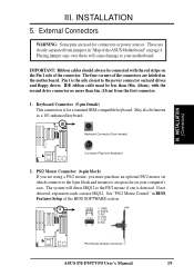
... 4. IMPORTANT: Ribbon cables should always be less than 18in. (46cm), with the red stripe on the Pin 1 side of the ASUS Motherboard" on your motherboard. Pin 1 is the side closest to your computer's case. IDE ribbon cable must purchase an optional PS/2 mouse set which connects...corners of the BIOS SOFTWARE section. 1 234 58 1 234 58 1: GND 2: DATA 3: NC 4: VCC 5: CLK 8: NC PS/2 Mouse Module Connector ASUS P/I-P55TVP4 User's Manual 19 Keyboard Connector (5-pin female) This connection is detected. PS/2 Mouse Connector (6-pin block) If you are used for a standard IBM-compatible...
... 4. IMPORTANT: Ribbon cables should always be less than 18in. (46cm), with the red stripe on the Pin 1 side of the ASUS Motherboard" on your motherboard. Pin 1 is the side closest to your computer's case. IDE ribbon cable must purchase an optional PS/2 mouse set which connects...corners of the BIOS SOFTWARE section. 1 234 58 1 234 58 1: GND 2: DATA 3: NC 4: VCC 5: CLK 8: NC PS/2 Mouse Module Connector ASUS P/I-P55TVP4 User's Manual 19 Keyboard Connector (5-pin female) This connection is detected. PS/2 Mouse Connector (6-pin block) If you are used for a standard IBM-compatible...
User Manual
Page 27
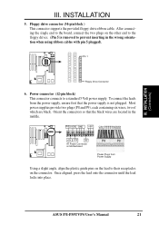
... drives. (Pin 5 is not plugged. ASUS P/I-P55TVP4 User's Manual 21 Power connector (12-pin block) This connector connects to prevent inserting in the middle. PG +12V GND +5V RED RED RED WHT BLK BLK BLK BLK BLU YLW RED ORG +5V -12V -5V AT Power Connector on Motherboard P8 P9 Power Plugs from...
... drives. (Pin 5 is not plugged. ASUS P/I-P55TVP4 User's Manual 21 Power connector (12-pin block) This connector connects to prevent inserting in the middle. PG +12V GND +5V RED RED RED WHT BLK BLK BLK BLK BLU YLW RED ORG +5V -12V -5V AT Power Connector on Motherboard P8 P9 Power Plugs from...
User Manual
Page 29
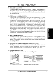
Turbo LED Lead (CON1) The motherboard's turbo function is powered on. This 2-pin connector (see the figure below . 13. Reset Switch Lead (CON1) This 2-pin connector connects to the case-mounted ... +5V GND SMI Lead GND Reset SW GND +5V NC Power LED & GND LOCK Keyboard Lock GND +5V Speaker GND Connector SPKR System Case Connections ASUS P/I-P55TVP4 User's Manual 23 SMI is labeled here but the keyboard will not cause any problems. May require one or two pushes depending on . See the...
Turbo LED Lead (CON1) The motherboard's turbo function is powered on. This 2-pin connector (see the figure below . 13. Reset Switch Lead (CON1) This 2-pin connector connects to the case-mounted ... +5V GND SMI Lead GND Reset SW GND +5V NC Power LED & GND LOCK Keyboard Lock GND +5V Speaker GND Connector SPKR System Case Connections ASUS P/I-P55TVP4 User's Manual 23 SMI is labeled here but the keyboard will not cause any problems. May require one or two pushes depending on . See the...


