
ME-99 User Manual
Page 1
R ME-99 Socket 370 Motherboard USER'S MANUAL
R ME-99 Socket 370 Motherboard USER'S MANUAL

ME-99 User Manual
Page 4
...1.1 How This Manual Is Organized 7 1.2 Item Checklist 7 2. HARDWARE SETUP 14 3.1 Motherboard Layout 14 3.2 Layout Contents 15 3.3 Hardware Setup Procedure 17 3.4 Motherboard Settings 17 3.5 System Memory (DIMM 24 3.5.1 VGA Shared Memory with DIMM 24 3.5.2 ...28 3.8 External Connectors 29 3.9 Power Connection Procedures 41 4. CONTENTS 1. FEATURES 8 2.1 The ASUS ME-99 Motherboard 8 2.1.1 Specifications 8 2.1.2 Performance 10 2.1.3 Intelligence 11 2.2 Parts of the ASUS ME-99 Motherboard 12 3. BIOS SETUP 42 4.1 Flash Memory Writer Utility 42 4.1.1 Main Menu 42 4.1.2 Managing...
...1.1 How This Manual Is Organized 7 1.2 Item Checklist 7 2. HARDWARE SETUP 14 3.1 Motherboard Layout 14 3.2 Layout Contents 15 3.3 Hardware Setup Procedure 17 3.4 Motherboard Settings 17 3.5 System Memory (DIMM 24 3.5.1 VGA Shared Memory with DIMM 24 3.5.2 ...28 3.8 External Connectors 29 3.9 Power Connection Procedures 41 4. CONTENTS 1. FEATURES 8 2.1 The ASUS ME-99 Motherboard 8 2.1.1 Specifications 8 2.1.2 Performance 10 2.1.3 Intelligence 11 2.2 Parts of the ASUS ME-99 Motherboard 12 3. BIOS SETUP 42 4.1 Flash Memory Writer Utility 42 4.1.1 Main Menu 42 4.1.2 Managing...
ME-99 User Manual
Page 7
If you discover damaged or missing items, please contact your retailer. (1) ASUS Motherboard (1) Ribbon cable for master and slave UltraDMA/33 IDE drives (1) Ribbon cable for master and slave UltraDMA/33 & UltraDMA/66 IDE drives (1) Ribbon ... 6) SOFTWARE REFERENCE Reference material for audio input/output and game/MIDI port (with audio chip onboard) ASUS IrDA-compliant infrared module (optional) ASUS PCI-L101 Wake-On-LAN 10/100 Fast Ethernet Card (optional) ASUS ME-99 User's Manual 7 1. INTRODUCTION 1.1 How This Manual Is Organized This manual is complete. INTRODUCTION Sections/...
If you discover damaged or missing items, please contact your retailer. (1) ASUS Motherboard (1) Ribbon cable for master and slave UltraDMA/33 IDE drives (1) Ribbon cable for master and slave UltraDMA/33 & UltraDMA/66 IDE drives (1) Ribbon ... 6) SOFTWARE REFERENCE Reference material for audio input/output and game/MIDI port (with audio chip onboard) ASUS IrDA-compliant infrared module (optional) ASUS PCI-L101 Wake-On-LAN 10/100 Fast Ethernet Card (optional) ASUS ME-99 User's Manual 7 1. INTRODUCTION 1.1 How This Manual Is Organized This manual is complete. INTRODUCTION Sections/...
ME-99 User Manual
Page 8
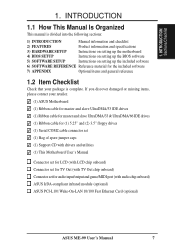
FEATURES Specifications 2. 2. FEATURES 2.1 The ASUS ME-99 Motherboard The ASUS ME-99 motherboard is carefully designed for the demanding PC user who wants many intelligent features in a small package....expansion slots. • Wake-On-LAN Connector: Supports Wake-On-LAN activity through an optional ethernet card (see 7.1 ASUS PCI-L101 Fast Ethernet Card). • Super Multi-I/O: Provides two high-speed UART compatible serial ports and one parallel ...(Requires DMI-enabled components.) • IrDA: Supports an optional infrared port module for wireless interface. 8 ASUS ME-99 User's Manual
FEATURES Specifications 2. 2. FEATURES 2.1 The ASUS ME-99 Motherboard The ASUS ME-99 motherboard is carefully designed for the demanding PC user who wants many intelligent features in a small package....expansion slots. • Wake-On-LAN Connector: Supports Wake-On-LAN activity through an optional ethernet card (see 7.1 ASUS PCI-L101 Fast Ethernet Card). • Super Multi-I/O: Provides two high-speed UART compatible serial ports and one parallel ...(Requires DMI-enabled components.) • IrDA: Supports an optional infrared port module for wireless interface. 8 ASUS ME-99 User's Manual
ME-99 User Manual
Page 10
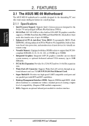
...99 User's Manual With these new technology is compatible with existing ATA-2 IDE specifications so there is no need to upgrade current IDE devices. • Concurrent PCI: Concurrent PCI allows multiple PCI transfers from PCI master buses to memory to CPU. • SDRAM Optimized Performance: ASUS smart series motherboards.../66 technology. To fully utilize the benefits of the motherboard meets PC'98 compliancy. ACPI provides more Energy Saving Features for configuring and managing all ASUS smart series motherboards. FEATURES Performance 2. 2. FEATURES 2.1.2 Performance • ...
...99 User's Manual With these new technology is compatible with existing ATA-2 IDE specifications so there is no need to upgrade current IDE devices. • Concurrent PCI: Concurrent PCI allows multiple PCI transfers from PCI master buses to memory to CPU. • SDRAM Optimized Performance: ASUS smart series motherboards.../66 technology. To fully utilize the benefits of the motherboard meets PC'98 compliancy. ACPI provides more Energy Saving Features for configuring and managing all ASUS smart series motherboards. FEATURES Performance 2. 2. FEATURES 2.1.2 Performance • ...

ME-99 User Manual
Page 11
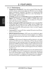
...warn the user before the system resources are more critical for future processors, so monitoring is the Soft-Off mode. With this motherboard supports Socket 370 processor thermal sensing. • Voltage Monitoring and Alert: System voltage levels are set for RPM and failure. Through... Function Power Button: The system can access vital information from their limited resources more memory and hard drive space to be in . ASUS ME-99 User's Manual 11 FEATURES 2.1.3 Intelligence • Fan Status Monitoring and Alarm: To prevent system overheat and system damage, the CPU,...
...warn the user before the system resources are more critical for future processors, so monitoring is the Soft-Off mode. With this motherboard supports Socket 370 processor thermal sensing. • Voltage Monitoring and Alert: System voltage levels are set for RPM and failure. Through... Function Power Button: The system can access vital information from their limited resources more memory and hard drive space to be in . ASUS ME-99 User's Manual 11 FEATURES 2.1.3 Intelligence • Fan Status Monitoring and Alarm: To prevent system overheat and system damage, the CPU,...

ME-99 User Manual
Page 12
FEATURES Parts 2. FEATURES 2.2 Parts of the ASUS ME-99 Motherboard The following are part descriptions for the motherboard parts shown on the next page. 1 Socket 370 for Intel Celeron 370 processors 2 ATX Power Connector for connection to an ATX power supply 3 SiS 620 ... model only) 22 VGA Monitor Output Connector 23 Parallel Connector 24 Serial COM1 Connector 25 Two USB Connectors 26 PS/2 Mouse, PS/2 Keyboard Connectors 12 ASUS ME-99 User's Manual 2.
FEATURES Parts 2. FEATURES 2.2 Parts of the ASUS ME-99 Motherboard The following are part descriptions for the motherboard parts shown on the next page. 1 Socket 370 for Intel Celeron 370 processors 2 ATX Power Connector for connection to an ATX power supply 3 SiS 620 ... model only) 22 VGA Monitor Output Connector 23 Parallel Connector 24 Serial COM1 Connector 25 Two USB Connectors 26 PS/2 Mouse, PS/2 Keyboard Connectors 12 ASUS ME-99 User's Manual 2.
ME-99 User Manual
Page 14
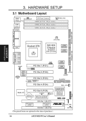
H/W SETUP Motherboard Layout PRINTER CPU_FAN VGA Line Out Socket 370 Thermal Sensor SiS 620 Chipset (Integrated AGP 2X VGA) 2 MB SDRAM 2 MB SDRAM GAME_AUDIO Line In Mic ... 1 (SLOT1) DIP Switches (DSW1) ISA Slot 1 (SLOT2) SiS5595 with Hardware Monitor & Keyboard Controller ME-99 IR ® CHA_FAN IDE LED (The grayed items are optional at the time of purchase.) 14 ASUS ME-99 User's Manual Panel HARDWARE SETUP 3.1 Motherboard Layout PS/2 KB WAKEUP T: Mouse B: Keyboard Row 5 4 USB 3 2 T: Port 1 B: Port 2 1 0 COM1 ATX Power Connector...
H/W SETUP Motherboard Layout PRINTER CPU_FAN VGA Line Out Socket 370 Thermal Sensor SiS 620 Chipset (Integrated AGP 2X VGA) 2 MB SDRAM 2 MB SDRAM GAME_AUDIO Line In Mic ... 1 (SLOT1) DIP Switches (DSW1) ISA Slot 1 (SLOT2) SiS5595 with Hardware Monitor & Keyboard Controller ME-99 IR ® CHA_FAN IDE LED (The grayed items are optional at the time of purchase.) 14 ASUS ME-99 User's Manual Panel HARDWARE SETUP 3.1 Motherboard Layout PS/2 KB WAKEUP T: Mouse B: Keyboard Row 5 4 USB 3 2 T: Port 1 B: Port 2 1 0 COM1 ATX Power Connector...
ME-99 User Manual
Page 15
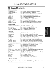
otherwise, conflicts will occur. ASUS ME-99 User's Manual 15 3. H/W SETUP Layout Contents 3. HARDWARE SETUP 3.2 Layout Contents Motherboard Settings 1) KB WAKEUP 2) DSW1-6, DSW1-7 3) DSW1-8 4) DSW2-5 5) DSW2-6 6) DSW2-7 7) DSW2-8 8) DSW1-1, 2, 3, 4 9) DSW1-5 10) DSW2-1, 2, 3, 4 p.18 Keyboard Wake Up Setting (Enable/Disable) p.19 I/O Voltage Setting (+0.1V/...
otherwise, conflicts will occur. ASUS ME-99 User's Manual 15 3. H/W SETUP Layout Contents 3. HARDWARE SETUP 3.2 Layout Contents Motherboard Settings 1) KB WAKEUP 2) DSW1-6, DSW1-7 3) DSW1-8 4) DSW2-5 5) DSW2-6 6) DSW2-7 7) DSW2-8 8) DSW1-1, 2, 3, 4 9) DSW1-5 10) DSW2-1, 2, 3, 4 p.18 Keyboard Wake Up Setting (Enable/Disable) p.19 I/O Voltage Setting (+0.1V/...
ME-99 User Manual
Page 17
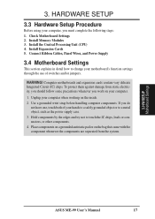
...the IC chips, leads or connectors, or other components. 4. Install Expansion Cards 5. Unplug your motherboard's function settings through the use of your computer. 1. H/W SETUP Motherboard Settings ASUS ME-99 User's Manual 17 Install the Central Processing Unit (CPU) 4. If you do not have one,... touch both of switches and/or jumpers. Connect Ribbon Cables, Panel Wires, and Power Supply 3.4 Motherboard Settings This section explains in...
...the IC chips, leads or connectors, or other components. 4. Install Expansion Cards 5. Unplug your motherboard's function settings through the use of your computer. 1. H/W SETUP Motherboard Settings ASUS ME-99 User's Manual 17 Install the Central Processing Unit (CPU) 4. If you do not have one,... touch both of switches and/or jumpers. Connect Ribbon Cables, Panel Wires, and Power Supply 3.4 Motherboard Settings This section explains in...

ME-99 User Manual
Page 18
.... 01 01 01 KB WAKEUP 123 Disable (Default) ME-99 ® ME-99 Keyboard Wake Up 123 Enable Motherboard Feature Settings (DIP Switches - Frequency Multiple 5. VGA Frame Buffer Setting 7. Core Voltage (Vcore) Setting 18 ASUS ME-99 User's Manual The white block represents the switch's position. ...not have the appropriate ATX power supply. Onboard Audio Setting ME-99 ® OFF ON ME-99 DIP Switches DSW2 ON 12345678 ON 12345678 DSW1 OFF ON 1. Frequency Selection 2. Memory Data Transfer 6. H/W SETUP Motherboard Settings 3. Set this to disable or enable the keyboard power ...
.... 01 01 01 KB WAKEUP 123 Disable (Default) ME-99 ® ME-99 Keyboard Wake Up 123 Enable Motherboard Feature Settings (DIP Switches - Frequency Multiple 5. VGA Frame Buffer Setting 7. Core Voltage (Vcore) Setting 18 ASUS ME-99 User's Manual The white block represents the switch's position. ...not have the appropriate ATX power supply. Onboard Audio Setting ME-99 ® OFF ON ME-99 DIP Switches DSW2 ON 12345678 ON 12345678 DSW1 OFF ON 1. Frequency Selection 2. Memory Data Transfer 6. H/W SETUP Motherboard Settings 3. Set this to disable or enable the keyboard power ...
ME-99 User Manual
Page 19
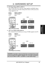
H/W SETUP Motherboard Settings 3. Setting Normal +0.1V DSW1-6, DSW1-7 [OFF] (default) [ON] DSW1 01 01 01 Normal (Default) Add 0.1 Volt ON 12345678 ON 12345678 Add 0.1 Volt Add 0.2 Volt ON 12345678 ON 12345678 ME-99 ® ME-99 I/O Voltage Setting 3) CPU Vcore Voltage Setting (DSW1-8) This switch allows... the core voltage (VCORE) supplied to [ON] increases the voltage supplied by 0.2V. Setting both switches to the CPU. ASUS ME-99 User's Manual 19 Using higher voltages may help when overclocking but may result in the shortening of your computer component's life. ...
H/W SETUP Motherboard Settings 3. Setting Normal +0.1V DSW1-6, DSW1-7 [OFF] (default) [ON] DSW1 01 01 01 Normal (Default) Add 0.1 Volt ON 12345678 ON 12345678 Add 0.1 Volt Add 0.2 Volt ON 12345678 ON 12345678 ME-99 ® ME-99 I/O Voltage Setting 3) CPU Vcore Voltage Setting (DSW1-8) This switch allows... the core voltage (VCORE) supplied to [ON] increases the voltage supplied by 0.2V. Setting both switches to the CPU. ASUS ME-99 User's Manual 19 Using higher voltages may help when overclocking but may result in the shortening of your computer component's life. ...
ME-99 User Manual
Page 20
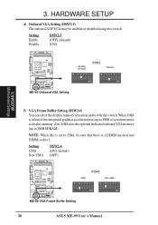
...memory. Setting Enable Disable DSW2-5 [OFF] (default) [ON] 01 01 01 ON 12345678 Enable (Default) DSW2 Disable ON 12345678 ME-99 ® ME-99 Onboard VGA Setting 3. When UMA is selected, the integrated graphics accelerator uses up to UMA, be enabled or disabled using this switch....UMA DSW2-6 [ON] (default) [OFF] 01 01 01 UMA DSW2 Non-UMA ON 12345678 ON 12345678 ME-99 ® ME-99 VGA Frame Buffer Setting 20 ASUS ME-99 User's Manual H/W SETUP Motherboard Settings 5) VGA Frame Buffer Setting (DSW2-6) You can select the display memory allocation mode with this switch. ...
...memory. Setting Enable Disable DSW2-5 [OFF] (default) [ON] 01 01 01 ON 12345678 Enable (Default) DSW2 Disable ON 12345678 ME-99 ® ME-99 Onboard VGA Setting 3. When UMA is selected, the integrated graphics accelerator uses up to UMA, be enabled or disabled using this switch....UMA DSW2-6 [ON] (default) [OFF] 01 01 01 UMA DSW2 Non-UMA ON 12345678 ON 12345678 ME-99 ® ME-99 VGA Frame Buffer Setting 20 ASUS ME-99 User's Manual H/W SETUP Motherboard Settings 5) VGA Frame Buffer Setting (DSW2-6) You can select the display memory allocation mode with this switch. ...

ME-99 User Manual
Page 21
... 01 01 01 Disable (Default) DSW2 Enable ON 12345678 ON 12345678 ME-99 ® ME-99 LCD Setting 7) Onboard Audio Setting (DSW2-8) The onboard 32-bit PCI audio may be enabled or disabled using an audio card on motherboards with this switch. Setting Enable Disable DSW2-8 [ON] [OFF] 01 ...01 01 Enable (Default) DSW2 Disable ON 12345678 ON 12345678 ME-99 ® ME-99 Onboard Audio Setting ASUS ME-99 User's Manual 21 LCD EN. Disable the onboard ...
... 01 01 01 Disable (Default) DSW2 Enable ON 12345678 ON 12345678 ME-99 ® ME-99 LCD Setting 7) Onboard Audio Setting (DSW2-8) The onboard 32-bit PCI audio may be enabled or disabled using an audio card on motherboards with this switch. Setting Enable Disable DSW2-8 [ON] [OFF] 01 ...01 01 Enable (Default) DSW2 Disable ON 12345678 ON 12345678 ME-99 ® ME-99 Onboard Audio Setting ASUS ME-99 User's Manual 21 LCD EN. Disable the onboard ...
ME-99 User Manual
Page 22
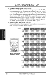
....00MHz 140.00MHz 35.00MHz 144.97MHz 145.00MHz 36.24MHz 150.00MHz 150.00MHz 37.50MHz 155.00MHz 155.00MHz 38.75MHz ME-99 ® ME-99 CPU External Frequency Setting (ASYNC) CPU 66.82MHz DIMM 100.23MHz PCI 33.41MHz (ASYNC) CPU DIMM PCI 100.23MHz 66.82MHz 33.41MHz... 93.33MHz 35.00MHz 144.97MHz 96.65MHz 36.24MHz 150.00MHz 100.00MHz 37.50MHz 155.00MHz 103.33MHz 38.75MHz 22 ASUS ME-99 User's Manual H/W SETUP Motherboard Settings 3. NOTE: You may set the memory clock frequency to be in synchronous or asynchronous mode with respect to the CPU, DRAM, and...
....00MHz 140.00MHz 35.00MHz 144.97MHz 145.00MHz 36.24MHz 150.00MHz 150.00MHz 37.50MHz 155.00MHz 155.00MHz 38.75MHz ME-99 ® ME-99 CPU External Frequency Setting (ASYNC) CPU 66.82MHz DIMM 100.23MHz PCI 33.41MHz (ASYNC) CPU DIMM PCI 100.23MHz 66.82MHz 33.41MHz... 93.33MHz 35.00MHz 144.97MHz 96.65MHz 36.24MHz 150.00MHz 100.00MHz 37.50MHz 155.00MHz 103.33MHz 38.75MHz 22 ASUS ME-99 User's Manual H/W SETUP Motherboard Settings 3. NOTE: You may set the memory clock frequency to be in synchronous or asynchronous mode with respect to the CPU, DRAM, and...
ME-99 User Manual
Page 23
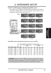
...5x(5/2) 12345678 12345678 12345678 ON ON ON 3.0x(3/1) 3.5x(7/2) 4.0x(4/1) 12345678 12345678 12345678 ON ON ON 12345678 12345678 12345678 4.5x(9/2) ME-99 ® ME-99 CPU Core:External Frequency Multiple 6.0x(6/1) ON 5.0x(5/1) 5.5x(11/2) ON 6.5x(13/2) 7.0x(7/1) ON 12345678 12345678 ON ON 7....] [OFF] [ON] [OFF] [ON] [ON] [OFF] [ON] [OFF] [OFF] [OFF] [ON] [OFF] [ON] [OFF] [ON] [ON] [OFF] WARNING! ASUS ME-99 User's Manual 23 01 01 01 3. Frequencies above 33MHz exceed the specifications for the onboard chipset and are not guaranteed to be set in conjunction...
...5x(5/2) 12345678 12345678 12345678 ON ON ON 3.0x(3/1) 3.5x(7/2) 4.0x(4/1) 12345678 12345678 12345678 ON ON ON 12345678 12345678 12345678 4.5x(9/2) ME-99 ® ME-99 CPU Core:External Frequency Multiple 6.0x(6/1) ON 5.0x(5/1) 5.5x(11/2) ON 6.5x(13/2) 7.0x(7/1) ON 12345678 12345678 ON ON 7....] [OFF] [ON] [OFF] [ON] [ON] [OFF] [ON] [OFF] [OFF] [OFF] [ON] [OFF] [ON] [OFF] [ON] [ON] [OFF] WARNING! ASUS ME-99 User's Manual 23 01 01 01 3. Frequencies above 33MHz exceed the specifications for the onboard chipset and are not guaranteed to be set in conjunction...

ME-99 User Manual
Page 24
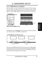
... are supported: SDRAM with and without ECC. • SDRAM chips are not PC100-compliant, set the memory bus frequency to 66MHz. • ASUS motherboards support SPD (Serial Presence Detect) DIMMs. This is the memory of choice for the onboard VGA, be sure that there is a DIMM inserted ...8226; For the system CPU bus to ensure system stability. tended Data Output) chips. • BIOS shows SDRAM memory on bootup screen. 24 ASUS ME-99 User's Manual HARDWARE SETUP 3.5 System Memory (DIMM) NOTE: No hardware or BIOS setup is recommended through SDRAM Configuration in any combination as follows...
... are supported: SDRAM with and without ECC. • SDRAM chips are not PC100-compliant, set the memory bus frequency to 66MHz. • ASUS motherboards support SPD (Serial Presence Detect) DIMMs. This is the memory of choice for the onboard VGA, be sure that there is a DIMM inserted ...8226; For the system CPU bus to ensure system stability. tended Data Output) chips. • BIOS shows SDRAM memory on bootup screen. 24 ASUS ME-99 User's Manual HARDWARE SETUP 3.5 System Memory (DIMM) NOTE: No hardware or BIOS setup is recommended through SDRAM Configuration in any combination as follows...
ME-99 User Manual
Page 25
... SETUP 3.5.3 DIMM Memory Installation Insert the module(s) as shown. ASUS ME-99 User's Manual 25 SIMM modules have a higher pin density. This motherboard supports four clock signals. 3. H/W SETUP System Memory 20 Pins 60 Pins 88 Pins ME-99 ® ME-99 168-Pin DIMM Sockets Front Lock The DIMMs must ask your ... wrong type from being inserted into the DIMM slot on both sides. 01 01 01 3. You must be 3.3V Unbuffered for this motherboard. Because the number of pins are longer and have different pin contact on each side and therefore have the same pin contact on the...
... SETUP 3.5.3 DIMM Memory Installation Insert the module(s) as shown. ASUS ME-99 User's Manual 25 SIMM modules have a higher pin density. This motherboard supports four clock signals. 3. H/W SETUP System Memory 20 Pins 60 Pins 88 Pins ME-99 ® ME-99 168-Pin DIMM Sockets Front Lock The DIMMs must ask your ... wrong type from being inserted into the DIMM slot on both sides. 01 01 01 3. You must be 3.3V Unbuffered for this motherboard. Because the number of pins are longer and have different pin contact on each side and therefore have the same pin contact on the...
ME-99 User Manual
Page 26
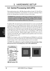
... your system may start. The picture below is not needed. H/W SETUP CPU 01 01 01 ME-99 ® ME-99 Socket 370 Notch 26 ASUS ME-99 User's Manual Be sure that there is required to scrape the motherboard when mounting a clampstyle processor fan or else damage may install an auxiliary fan, if necessary. Without...
... your system may start. The picture below is not needed. H/W SETUP CPU 01 01 01 ME-99 ® ME-99 Socket 370 Notch 26 ASUS ME-99 User's Manual Be sure that there is required to scrape the motherboard when mounting a clampstyle processor fan or else damage may install an auxiliary fan, if necessary. Without...
ME-99 User Manual
Page 27
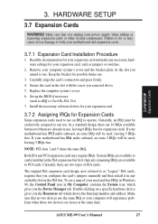
...Windows 98, the Control Panel icon in any remaining IRQs are in use at the same time. If your motherboard and expansion cards. 3.7.1 Expansion Card Installation Procedure 1. Double-clicking on the slot you configure the card's ...icon, which gives you the Resources tab which shows the Interrupt number and address. Keep the bracket for your motherboard has ISA audio onboard, an extra 3 IRQs will experience problems when those two devices are available to as "... if necessary (such as jumpers or switches. 2. Secure the card on the ISA bus. ASUS ME-99 User's Manual 27
...Windows 98, the Control Panel icon in any remaining IRQs are in use at the same time. If your motherboard and expansion cards. 3.7.1 Expansion Card Installation Procedure 1. Double-clicking on the slot you configure the card's ...icon, which gives you the Resources tab which shows the Interrupt number and address. Keep the bracket for your motherboard has ISA audio onboard, an extra 3 IRQs will experience problems when those two devices are available to as "... if necessary (such as jumpers or switches. 2. Secure the card on the ISA bus. ASUS ME-99 User's Manual 27


