
ME-99 User Manual
Page 4
... the ASUS ME-99 Motherboard 12 3. HARDWARE SETUP 14 3.1 Motherboard Layout 14 3.2 Layout Contents 15 3.3 Hardware Setup Procedure 17 3.4 Motherboard Settings 17 3.5 System Memory (DIMM 24 3.5.1 VGA Shared Memory with DIMM 24 3.5.2 General DIMM Notes 24 3.5.3 DIMM Memory Installation 25 3.6 Central Processing Unit (CPU 26 3.7 Expansion Cards 27 3.7.1 Expansion Card Installation Procedure 27 3.7.2 Assigning IRQs for Expansion Cards 27 3.7.3 Assigning DMA Channels for ISA Cards 28 3.7.4 ISA Cards and Hardware Monitor 28 3.8 External Connectors 29 3.9 Power Connection...
... the ASUS ME-99 Motherboard 12 3. HARDWARE SETUP 14 3.1 Motherboard Layout 14 3.2 Layout Contents 15 3.3 Hardware Setup Procedure 17 3.4 Motherboard Settings 17 3.5 System Memory (DIMM 24 3.5.1 VGA Shared Memory with DIMM 24 3.5.2 General DIMM Notes 24 3.5.3 DIMM Memory Installation 25 3.6 Central Processing Unit (CPU 26 3.7 Expansion Cards 27 3.7.1 Expansion Card Installation Procedure 27 3.7.2 Assigning IRQs for Expansion Cards 27 3.7.3 Assigning DMA Channels for ISA Cards 28 3.7.4 ISA Cards and Hardware Monitor 28 3.8 External Connectors 29 3.9 Power Connection...
ME-99 User Manual
Page 7
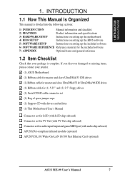
... Product information and specifications 3) HARDWARE SETUP Instructions on setting up the motherboard 4) BIOS SETUP Instructions on setting up the BIOS software 5) SOFTWARE SETUP Instructions on setting up the included software 6) SOFTWARE REFERENCE Reference material for audio input/output and game/MIDI port (with audio chip onboard) ASUS IrDA-compliant infrared module (optional) ASUS PCI-L101 Wake-On-LAN 10/100 Fast Ethernet Card (optional) ASUS ME-99 User's Manual 7 INTRODUCTION Sections/Checklist 1. INTRODUCTION 1.1 How This Manual Is Organized This manual is complete.
... Product information and specifications 3) HARDWARE SETUP Instructions on setting up the motherboard 4) BIOS SETUP Instructions on setting up the BIOS software 5) SOFTWARE SETUP Instructions on setting up the included software 6) SOFTWARE REFERENCE Reference material for audio input/output and game/MIDI port (with audio chip onboard) ASUS IrDA-compliant infrared module (optional) ASUS PCI-L101 Wake-On-LAN 10/100 Fast Ethernet Card (optional) ASUS ME-99 User's Manual 7 INTRODUCTION Sections/Checklist 1. INTRODUCTION 1.1 How This Manual Is Organized This manual is complete.
ME-99 User Manual
Page 8
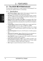
... 768MB. • Integrated Graphics: Integrated AGP 2X graphics controller can use shared system memory or optional dedicated onboard VGA memory (up to 8MB SDRAM). • PCI & ISA Expansion: Provides five 32-bit PCI and two 16-bit ISA expansion slots. • Wake-On-LAN Connector: Supports Wake-On-LAN activity through an optional ethernet card (see 7.1 ASUS PCI-L101 Fast Ethernet Card). • Super Multi-I/O: Provides two high-speed UART compatible serial ports and one parallel port with EPP and ECP...
... 768MB. • Integrated Graphics: Integrated AGP 2X graphics controller can use shared system memory or optional dedicated onboard VGA memory (up to 8MB SDRAM). • PCI & ISA Expansion: Provides five 32-bit PCI and two 16-bit ISA expansion slots. • Wake-On-LAN Connector: Supports Wake-On-LAN activity through an optional ethernet card (see 7.1 ASUS PCI-L101 Fast Ethernet Card). • Super Multi-I/O: Provides two high-speed UART compatible serial ports and one parallel port with EPP and ECP...
ME-99 User Manual
Page 10
... an onboard PCI Bus Master IDE controller with existing ATA-2 IDE specifications so there is no need to upgrade current IDE devices. • Concurrent PCI: Concurrent PCI allows multiple PCI transfers from PCI master buses to memory to CPU. • SDRAM Optimized Performance: ASUS smart series motherboards support the new generation memory, Synchronous Dynamic Random Access Memory (SDRAM), which increases the data transfer rate to 66MB/s using PC100 SDRAM. • ACPI Ready: ACPI (Advanced Configuration and Power Interface) is compatible...
... an onboard PCI Bus Master IDE controller with existing ATA-2 IDE specifications so there is no need to upgrade current IDE devices. • Concurrent PCI: Concurrent PCI allows multiple PCI transfers from PCI master buses to memory to CPU. • SDRAM Optimized Performance: ASUS smart series motherboards support the new generation memory, Synchronous Dynamic Random Access Memory (SDRAM), which increases the data transfer rate to 66MB/s using PC100 SDRAM. • ACPI Ready: ACPI (Advanced Configuration and Power Interface) is compatible...

ME-99 User Manual
Page 11
... an internal or external modem. With this motherboard supports Socket 370 processor thermal sensing. • Voltage Monitoring and Alert: System voltage levels are set for less than 4 seconds, it enters the Soft-Off mode. • Remote Ring On (requires modem): This allows a computer to critical motherboard components. ASUS ME-99 User's Manual 11 All the fans are monitored to ensure stable current to be powered ON using your keyboard. 2. When the power button...
... an internal or external modem. With this motherboard supports Socket 370 processor thermal sensing. • Voltage Monitoring and Alert: System voltage levels are set for less than 4 seconds, it enters the Soft-Off mode. • Remote Ring On (requires modem): This allows a computer to critical motherboard components. ASUS ME-99 User's Manual 11 All the fans are monitored to ensure stable current to be powered ON using your keyboard. 2. When the power button...

ME-99 User Manual
Page 12
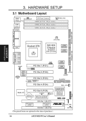
... Parts 2. FEATURES 2.2 Parts of the ASUS ME-99 Motherboard The following are part descriptions for the motherboard parts shown on the next page. 1 Socket 370 for Intel Celeron 370 processors 2 ATX Power Connector for connection to an ATX power supply 3 SiS 620 AGPset 4 Three DIMM Sockets 5 Optional Onboard VGA Memory (up to 8MB) 6 Primary and Secondary IDE Connectors 7 LCD Header (with LCD chip onboard) 8 Wake-On-LAN Connector 9 TV Out Interface (with TV Out chip onboard) 10 LCD Chip (optional) 11 SiS 5595 PCI System I/O Chipset...
... Parts 2. FEATURES 2.2 Parts of the ASUS ME-99 Motherboard The following are part descriptions for the motherboard parts shown on the next page. 1 Socket 370 for Intel Celeron 370 processors 2 ATX Power Connector for connection to an ATX power supply 3 SiS 620 AGPset 4 Three DIMM Sockets 5 Optional Onboard VGA Memory (up to 8MB) 6 Primary and Secondary IDE Connectors 7 LCD Header (with LCD chip onboard) 8 Wake-On-LAN Connector 9 TV Out Interface (with TV Out chip onboard) 10 LCD Chip (optional) 11 SiS 5595 PCI System I/O Chipset...
ME-99 User Manual
Page 14
... SCART FLOPPY WOL_CON Multi-I/O PCI Slot 5 (PCI5) CR2032 3V Lithium Cell CMOS Power CLRRTC 2Mbit Flash EEPROM (Programmable BIOS) WOR DIP Switches (DSW2) ISA Slot 1 (SLOT1) DIP Switches (DSW1) ISA Slot 1 (SLOT2) SiS5595 with Hardware Monitor & Keyboard Controller ME-99 IR ® CHA_FAN IDE LED (The grayed items are optional at the time of purchase.) 14 ASUS ME-99 User's Manual Panel HARDWARE SETUP 3.1 Motherboard Layout PS/2 KB WAKEUP T: Mouse B: Keyboard Row 5 4 USB 3 2 T: Port 1 B: Port 2 1 0 COM1 ATX Power Connector DIMM3 (64/72-bit, 168-pin...
... SCART FLOPPY WOL_CON Multi-I/O PCI Slot 5 (PCI5) CR2032 3V Lithium Cell CMOS Power CLRRTC 2Mbit Flash EEPROM (Programmable BIOS) WOR DIP Switches (DSW2) ISA Slot 1 (SLOT1) DIP Switches (DSW1) ISA Slot 1 (SLOT2) SiS5595 with Hardware Monitor & Keyboard Controller ME-99 IR ® CHA_FAN IDE LED (The grayed items are optional at the time of purchase.) 14 ASUS ME-99 User's Manual Panel HARDWARE SETUP 3.1 Motherboard Layout PS/2 KB WAKEUP T: Mouse B: Keyboard Row 5 4 USB 3 2 T: Port 1 B: Port 2 1 0 COM1 ATX Power Connector DIMM3 (64/72-bit, 168-pin...
ME-99 User Manual
Page 15
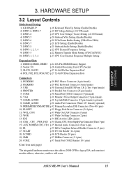
... ASUS ME-99 User's Manual 15 HARDWARE SETUP 3.2 Layout Contents Motherboard Settings 1) KB WAKEUP 2) DSW1-6, DSW1-7 3) DSW1-8 4) DSW2-5 5) DSW2-6 6) DSW2-7 7) DSW2-8 8) DSW1-1, 2, 3, 4 9) DSW1-5 10) DSW2-1, 2, 3, 4 p.18 Keyboard Wake Up Setting (Enable/Disable) p.19 I/O Voltage Setting (+0.1V/Normal) p.19 CPU Core Voltage (Vcore) Setting (+0.1V/Normal) p.20 Onboard VGA Setting (Enable/Disable) p.20 VGA Frame Buffer Setting (UMA/Non-UMA) p.21 LCD Setting (Enable/Disable) p.21 Onboard Audio Setting (Enable/Disable) p.22 CPU External Frequency Setting p.22 Memory Transfer Mode Setting...
... ASUS ME-99 User's Manual 15 HARDWARE SETUP 3.2 Layout Contents Motherboard Settings 1) KB WAKEUP 2) DSW1-6, DSW1-7 3) DSW1-8 4) DSW2-5 5) DSW2-6 6) DSW2-7 7) DSW2-8 8) DSW1-1, 2, 3, 4 9) DSW1-5 10) DSW2-1, 2, 3, 4 p.18 Keyboard Wake Up Setting (Enable/Disable) p.19 I/O Voltage Setting (+0.1V/Normal) p.19 CPU Core Voltage (Vcore) Setting (+0.1V/Normal) p.20 Onboard VGA Setting (Enable/Disable) p.20 VGA Frame Buffer Setting (UMA/Non-UMA) p.21 LCD Setting (Enable/Disable) p.21 Onboard Audio Setting (Enable/Disable) p.22 CPU External Frequency Setting p.22 Memory Transfer Mode Setting...

ME-99 User Manual
Page 18
... switch's position. Frequency Multiple 3. VGA Frame Buffer Setting 7. Onboard Audio Setting ME-99 ® OFF ON ME-99 DIP Switches DSW2 ON 12345678 ON 12345678 DSW1 OFF ON 1. Frequency Selection 5. Core Voltage (Vcore) Setting 18 ASUS ME-99 User's Manual Set this to power up function. Frequency Multiple 4. Onboard VGA Setting 6. HARDWARE SETUP 1) Keyboard Wake Up (3-pin KB WAKEUP) This allows you to disable or enable the keyboard power up your motherboard) to Enable and do not have the appropriate ATX power supply. Your computer will not power...
... switch's position. Frequency Multiple 3. VGA Frame Buffer Setting 7. Onboard Audio Setting ME-99 ® OFF ON ME-99 DIP Switches DSW2 ON 12345678 ON 12345678 DSW1 OFF ON 1. Frequency Selection 5. Core Voltage (Vcore) Setting 18 ASUS ME-99 User's Manual Set this to power up function. Frequency Multiple 4. Onboard VGA Setting 6. HARDWARE SETUP 1) Keyboard Wake Up (3-pin KB WAKEUP) This allows you to disable or enable the keyboard power up your motherboard) to Enable and do not have the appropriate ATX power supply. Your computer will not power...

ME-99 User Manual
Page 24
...-compliant, set the memory bus frequency to 66MHz. • ASUS motherboards support SPD (Serial Presence Detect) DIMMs. This is a DIMM inserted into DIMM socket 1. 3.5.2 General DIMM Notes • For the system CPU bus to operate at 100MHz, use only PC100-compliant DIMMs. When this speed. tended Data Output) chips. • BIOS shows SDRAM memory on bootup screen. 24 ASUS ME-99 User's Manual HARDWARE SETUP 3.5 System Memory (DIMM) NOTE: No hardware or BIOS setup is...
...-compliant, set the memory bus frequency to 66MHz. • ASUS motherboards support SPD (Serial Presence Detect) DIMMs. This is a DIMM inserted into DIMM socket 1. 3.5.2 General DIMM Notes • For the system CPU bus to operate at 100MHz, use only PC100-compliant DIMMs. When this speed. tended Data Output) chips. • BIOS shows SDRAM memory on bootup screen. 24 ASUS ME-99 User's Manual HARDWARE SETUP 3.5 System Memory (DIMM) NOTE: No hardware or BIOS setup is...
ME-99 User Manual
Page 27
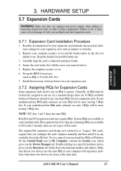
... but most of your used and free IRQs in Windows 98, the Control Panel icon in any necessary hardware settings for Expansion Cards Some expansion cards need to use an IRQ to one use the same IRQ or your expansion card, such as jumpers or switches. 2. Make sure that no two devices use . H/W SETUP Expansion Cards 3. Make sure that you configure the card's jumpers manually and then install it in My Computer...
... but most of your used and free IRQs in Windows 98, the Control Panel icon in any necessary hardware settings for Expansion Cards Some expansion cards need to use an IRQ to one use the same IRQ or your expansion card, such as jumpers or switches. 2. Make sure that no two devices use . H/W SETUP Expansion Cards 3. Make sure that you configure the card's jumpers manually and then install it in My Computer...
ME-99 User Manual
Page 39
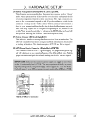
... ME-99 ® ME-99 ATX Power Connector ASUS ME-99 User's Manual 39 SMI is activated when it shorted will always allow wake-up (the SMI lead cannot wake up can supply at least 720mA +5VSB. 3. This function requires ACPI OS and driver support. 28) ATX Power Supply Connector (20-pin block ATXPWR) This connector connects to the case-mounted suspend switch. The plug from a fax/modem. Wake-up the system). 27) System Message LED Lead (2-pin LED) This...
... ME-99 ® ME-99 ATX Power Connector ASUS ME-99 User's Manual 39 SMI is activated when it shorted will always allow wake-up (the SMI lead cannot wake up can supply at least 720mA +5VSB. 3. This function requires ACPI OS and driver support. 28) ATX Power Supply Connector (20-pin block ATXPWR) This connector connects to the case-mounted suspend switch. The plug from a fax/modem. Wake-up the system). 27) System Message LED Lead (2-pin LED) This...
ME-99 User Manual
Page 41
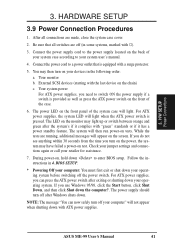
... light. If you need to enter BIOS setup. HARDWARE SETUP 3.9 Power Connection Procedures 1. BIOS SETUP. * Powering Off your system case according to a power outlet that all connections are running, additional messages will not appear when shutting down . During power-on test. Your system power For ATX power supplies, you use Windows 95/98, click the Start button, click Shut Down, and then click Shut down your operating system before switching off your devices in 4. Connect...
... light. If you need to enter BIOS setup. HARDWARE SETUP 3.9 Power Connection Procedures 1. BIOS SETUP. * Powering Off your system case according to a power outlet that all connections are running, additional messages will not appear when shutting down . During power-on test. Your system power For ATX power supplies, you use Windows 95/98, click the Start button, click Shut Down, and then click Shut down your operating system before switching off your devices in 4. Connect...

ME-99 User Manual
Page 42
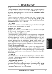
... press . 42 ASUS ME-99 User's Manual BIOS SETUP 4.1 Flash Memory Writer Utility AFLASH.EXE: This is not supported by the ACPI BIOS and therefore, cannot be programmed by uploading a new BIOS file to the programmable flash ROM chip on your system. 4. NOTE: The following screen displays are provided as examples only and may not reflect the screen contents displayed on the motherboard. BIOS SETUP Flash Memory Writer IMPORTANT: If "unknown" is displayed after Flash Memory:, the memory chip is either...
... press . 42 ASUS ME-99 User's Manual BIOS SETUP 4.1 Flash Memory Writer Utility AFLASH.EXE: This is not supported by the ACPI BIOS and therefore, cannot be programmed by uploading a new BIOS file to the programmable flash ROM chip on your system. 4. NOTE: The following screen displays are provided as examples only and may not reflect the screen contents displayed on the motherboard. BIOS SETUP Flash Memory Writer IMPORTANT: If "unknown" is displayed after Flash Memory:, the memory chip is either...
ME-99 User Manual
Page 51
... transfer speeds and data integrity for the drive. Configuration options: [0] [1] [2] [3] [4] [Disabled] 4. 4. Sector This field configures the number of the S.M.A.R.T. (Self-Monitoring, Analysis and Reporting Technology) system which utilizes internal hard disk drive monitoring technology. This field can also be the fastest value for compatible IDE devices. Note that came with your hard drive to determine the optimal value and set to the highest number supported by the drive. Configuration options: [Disabled] [Enabled] PIO Mode [4] This option lets you set value...
... transfer speeds and data integrity for the drive. Configuration options: [0] [1] [2] [3] [4] [Disabled] 4. 4. Sector This field configures the number of the S.M.A.R.T. (Self-Monitoring, Analysis and Reporting Technology) system which utilizes internal hard disk drive monitoring technology. This field can also be the fastest value for compatible IDE devices. Note that came with your hard drive to determine the optimal value and set to the highest number supported by the drive. Configuration options: [Disabled] [Enabled] PIO Mode [4] This option lets you set value...

ME-99 User Manual
Page 56
... display card cannot support this feature, otherwise your system may not boot. It can select to motherboards with onboard VGA but no VGA memory onboard. SDRAM Refresh Mode [Simultaneous] Leave on default setting. This option is a new cache technology for ISA expansion cards that require it. 4. Configuration options: [Disabled] [Enabled] Onboard PCI IDE Enable [Both] You can greatly improve the display speed by caching the display data. ROM Cycle Wait State [1-Wait] Leave on default setting. 8-bit, 16-bit I/O Recovery Time Leave on default setting...
... display card cannot support this feature, otherwise your system may not boot. It can select to motherboards with onboard VGA but no VGA memory onboard. SDRAM Refresh Mode [Simultaneous] Leave on default setting. This option is a new cache technology for ISA expansion cards that require it. 4. Configuration options: [Disabled] [Enabled] Onboard PCI IDE Enable [Both] You can greatly improve the display speed by caching the display data. ROM Cycle Wait State [1-Wait] Leave on default setting. 8-bit, 16-bit I/O Recovery Time Leave on default setting...
ME-99 User Manual
Page 57
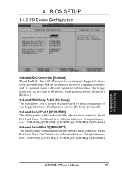
...: [3E8H/IRQ4] [2F8H/IRQ3] [3F8H/IRQ4] [2E8H/IRQ10] [Disabled] ASUS ME-99 User's Manual 57 4. BIOS SETUP 4.4.2 I /O Device Config. Configuration options: [3F8H/IRQ4] [2F8H/IRQ3] [3E8H/IRQ4] [2E8H/IRQ10] [Disabled] Onboard Serial Port 2 [2F8H/IRQ3] This allows you want to use a different controller card to connect the floppy disk drives, set this field allows you to reverse the hardware drive letter assignments of a separate controller card. BIOS SETUP I /O Device Configuration 4. Configuration options: [Disabled] [Enabled] Onboard FDC Swap A & B [No Swap] This field allows you...
...: [3E8H/IRQ4] [2F8H/IRQ3] [3F8H/IRQ4] [2E8H/IRQ10] [Disabled] ASUS ME-99 User's Manual 57 4. BIOS SETUP 4.4.2 I /O Device Config. Configuration options: [3F8H/IRQ4] [2F8H/IRQ3] [3E8H/IRQ4] [2E8H/IRQ10] [Disabled] Onboard Serial Port 2 [2F8H/IRQ3] This allows you want to use a different controller card to connect the floppy disk drives, set this field allows you to reverse the hardware drive letter assignments of a separate controller card. BIOS SETUP I /O Device Configuration 4. Configuration options: [Disabled] [Enabled] Onboard FDC Swap A & B [No Swap] This field allows you...
ME-99 User Manual
Page 60
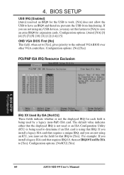
... IRQ# and therefore prevents the USB from functioning. 4. Configuration options: [No] [Yes] PCI/PNP ISA IRQ Resource Exclusion 4. BIOS SETUP USB IRQ [Enabled] [Auto] reserved an IRQ# for that requires IRQ 10, then set IRQ10 Used By ISA to the onboard VGA BIOS over other VGA controllers. The default value indicates either that the displayed IRQ is not used or an ISA Configuration Utility (ICU) is being used by a legacy (non-PnP) ISA...
... IRQ# and therefore prevents the USB from functioning. 4. Configuration options: [No] [Yes] PCI/PNP ISA IRQ Resource Exclusion 4. BIOS SETUP USB IRQ [Enabled] [Auto] reserved an IRQ# for that requires IRQ 10, then set IRQ10 Used By ISA to the onboard VGA BIOS over other VGA controllers. The default value indicates either that the displayed IRQ is not used or an ISA Configuration Utility (ICU) is being used by a legacy (non-PnP) ISA...
ME-99 User Manual
Page 72
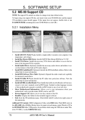
... integrated VGA controller. • Install Audio Driver (Optional): Installs the necessary audio drivers and utilities to fix problems when using your support CD disc, just insert it into your CD-ROM drive is available in the USBPATCH folder. 72 ASUS ME-99 User's Manual essary to access the fea- 5. To begin using the USB driver under Windows 95 OSR 2.1 in PDF format at any of the main menu. S/W SETUP Windows 98 • Install ASUS PC Probe Vx.xx: Installs a simple utility to monitor your motherboard...
... integrated VGA controller. • Install Audio Driver (Optional): Installs the necessary audio drivers and utilities to fix problems when using your support CD disc, just insert it into your CD-ROM drive is available in the USBPATCH folder. 72 ASUS ME-99 User's Manual essary to access the fea- 5. To begin using the USB driver under Windows 95 OSR 2.1 in PDF format at any of the main menu. S/W SETUP Windows 98 • Install ASUS PC Probe Vx.xx: Installs a simple utility to monitor your motherboard...
ME-99 User Manual
Page 99
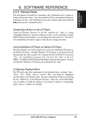
... only display six of each input by setting its corresponding binary value to 1 (enable) or 0 (disable). AudioRack can change without prior notice. SOFTWARE REFERENCE 6.2.9 Release Notes This information is a string "DisableEjectButton=0" under the [cdplayer] section. Configuring Playback Mixer The PCI audio chip offers eight inputs for convenience only. Information here is inserted into the CD-ROM. Using AudioRack CD Player as Default CD...
... only display six of each input by setting its corresponding binary value to 1 (enable) or 0 (disable). AudioRack can change without prior notice. SOFTWARE REFERENCE 6.2.9 Release Notes This information is a string "DisableEjectButton=0" under the [cdplayer] section. Configuring Playback Mixer The PCI audio chip offers eight inputs for convenience only. Information here is inserted into the CD-ROM. Using AudioRack CD Player as Default CD...


