
User Manual
Page 1
M3N WS Motherboard
M3N WS Motherboard
User Manual
Page 3
Contents Contents...iii Notices...vii Safety information viii About this guide ix M3N WS specifications summary xi Chapter 1: Product introduction 1.1 Welcome 1-1 1.2 Package contents 1-1 1.3 Special features 1-2 1.3.1 Product highlights 1-2 1.3.2 ASUS unique features 1-4 1.3.3 ASUS intelligent performance and overclocking features 1-6 Chapter 2: Hardware information 2.1 Before you proceed 2-1 2.2 Motherboard overview 2-2 2.2.1 Motherboard layout 2-2 2.2.2 Layout contents 2-3 2.2.3 Placement direction 2-4 2.2.4 Screw holes 2-4 2.3 Central Processing Unit (CPU 2-5 2.3.1 ...
Contents Contents...iii Notices...vii Safety information viii About this guide ix M3N WS specifications summary xi Chapter 1: Product introduction 1.1 Welcome 1-1 1.2 Package contents 1-1 1.3 Special features 1-2 1.3.1 Product highlights 1-2 1.3.2 ASUS unique features 1-4 1.3.3 ASUS intelligent performance and overclocking features 1-6 Chapter 2: Hardware information 2.1 Before you proceed 2-1 2.2 Motherboard overview 2-2 2.2.1 Motherboard layout 2-2 2.2.2 Layout contents 2-3 2.2.3 Placement direction 2-4 2.2.4 Screw holes 2-4 2.3 Central Processing Unit (CPU 2-5 2.3.1 ...
User Manual
Page 8
... are not sure about the voltage of the electrical outlet you add a device. • Before connecting or removing signal cables from the motherboard, ensure that all power cables from the existing system before you are unplugged. • Seek professional assistance before using the product, make ...or your retailer. Check local regulations for the devices are unplugged before the signal cables are not damaged. Operation safety • Before installing the motherboard and adding devices on it may become wet. • Place the product on a stable surface. • If you detect any area ...
... are not sure about the voltage of the electrical outlet you add a device. • Before connecting or removing signal cables from the motherboard, ensure that all power cables from the existing system before you are unplugged. • Seek professional assistance before using the product, make ...or your retailer. Check local regulations for the devices are unplugged before the signal cables are not damaged. Operation safety • Before installing the motherboard and adding devices on it may become wet. • Place the product on a stable surface. • If you detect any area ...

User Manual
Page 9
... descriptions of the BIOS parameters are not part of the switches, jumpers, and connectors on ASUS hardware and software products. ASUS websites The ASUS website provides updated information on the motherboard. • Chapter 3: BIOS setup This chapter tells how to change system settings through the... Hardware information This chapter lists the hardware setup procedures that you need when installing and configuring the motherboard. Where to find more information Refer to the ASUS contact information. 2. How this guide This user guide contains the information you have been added by ...
... descriptions of the BIOS parameters are not part of the switches, jumpers, and connectors on ASUS hardware and software products. ASUS websites The ASUS website provides updated information on the motherboard. • Chapter 3: BIOS setup This chapter tells how to change system settings through the... Hardware information This chapter lists the hardware setup procedures that you need when installing and configuring the motherboard. Where to find more information Refer to the ASUS contact information. 2. How this guide This user guide contains the information you have been added by ...

User Manual
Page 15
Chapter 1: 1Product introduction This chapter describes the motherboard features and the new technologies it supports.
Chapter 1: 1Product introduction This chapter describes the motherboard features and the new technologies it supports.
User Manual
Page 17
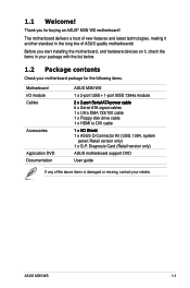
Retail version only) 1 x G.P. Diagnosis Card (Retail version only) Application DVD ASUS motherboard support DVD Documentation User guide If any of ASUS quality motherboards! Before you for the following items. Motherboard ASUS M3N WS I/O module 1 x 2-port USB + 1-port IEEE 1394a module Cables 2���x�2�-p�o�rt�S�e�ri�al�A�T�A&#...
Retail version only) 1 x G.P. Diagnosis Card (Retail version only) Application DVD ASUS motherboard support DVD Documentation User guide If any of ASUS quality motherboards! Before you for the following items. Motherboard ASUS M3N WS I/O module 1 x 2-port USB + 1-port IEEE 1394a module Cables 2���x�2�-p�o�rt�S�e�ri�al�A�T�A&#...
User Manual
Page 18
...excellent system performance. See page 2‑10 for details. AMD® Socket AM2 Athlon™ Series / Sempron™ CPU support This motherboard supports AMD® Socket AM2 Athlon™ Series / Sempron™ processors. HyperTransport™ 3.0 support HyperTransport™ 3.0 technology provides 2.6 times ... radically improving system efficiency to 5200MT/s via HyperTransport™ 3.0 based system bus. 1.3 Special features 1.3.1 Product highlights Green ASUS This motherboard and its packaging comply with the European Union's Restriction on the environment.
...excellent system performance. See page 2‑10 for details. AMD® Socket AM2 Athlon™ Series / Sempron™ CPU support This motherboard supports AMD® Socket AM2 Athlon™ Series / Sempron™ processors. HyperTransport™ 3.0 support HyperTransport™ 3.0 technology provides 2.6 times ... radically improving system efficiency to 5200MT/s via HyperTransport™ 3.0 based system bus. 1.3 Special features 1.3.1 Product highlights Green ASUS This motherboard and its packaging comply with the European Union's Restriction on the environment.
User Manual
Page 19
... the latest PCIe 2.0 devices for details. Serial ATA 3.0 Gb/s technology This motherboard supports the next-generation hard disk drives based on select GeForce GPUs. You can switch from the discrete GeForce GPU(s) to -DVI conversion adaptor. ASUS M3N WS 1-3 It includes two primary features: GeForce Boost and HybridPower™. See page 2-20 and Chapter...
... the latest PCIe 2.0 devices for details. Serial ATA 3.0 Gb/s technology This motherboard supports the next-generation hard disk drives based on select GeForce GPUs. You can switch from the discrete GeForce GPU(s) to -DVI conversion adaptor. ASUS M3N WS 1-3 It includes two primary features: GeForce Boost and HybridPower™. See page 2-20 and Chapter...
User Manual
Page 20
...24 for details. 1-4 Chapter 1: Product Introduction G.P. ASUS SASsaby cards support This motherboard is fully compatible with M3N WS motherboard (retail version), the G.P. See page 2-20 for details. 1.3.2 ASUS unique features ASUS Power Saving Solution ASUS Power Saving solution intelligently and automatically provides balanced computing ... AI Nap, the system can real-time chnage the mode under operating system to your needs. ASUS Workstation Features ASUS Workstation features provide complete support to different destinations. The onboard 8-channel HD audio (High Definition Audio...
...24 for details. 1-4 Chapter 1: Product Introduction G.P. ASUS SASsaby cards support This motherboard is fully compatible with M3N WS motherboard (retail version), the G.P. See page 2-20 for details. 1.3.2 ASUS unique features ASUS Power Saving Solution ASUS Power Saving solution intelligently and automatically provides balanced computing ... AI Nap, the system can real-time chnage the mode under operating system to your needs. ASUS Workstation Features ASUS Workstation features provide complete support to different destinations. The onboard 8-channel HD audio (High Definition Audio...
User Manual
Page 21
...components to the other side of the innovative heat pipe design on this motherboard is that the groundbreaking fanless design does not have lifetime problems as a chipset fan does. ASUS EZ DIY ASUS EZ DIY feature collection provides you easy ways to install side-flow ...fan speeds according to system loading to the heatsink near the back IO ports, where it ideally protects your favorite settings. ASUS M3N WS 1-5 ASUS Q-Shield The specially designed ASUS Q-Shield does without the usual "fingers"- The purpose of the specially designed PCB (printed circuit board) for details. See...
...components to the other side of the innovative heat pipe design on this motherboard is that the groundbreaking fanless design does not have lifetime problems as a chipset fan does. ASUS EZ DIY ASUS EZ DIY feature collection provides you easy ways to install side-flow ...fan speeds according to system loading to the heatsink near the back IO ports, where it ideally protects your favorite settings. ASUS M3N WS 1-5 ASUS Q-Shield The specially designed ASUS Q-Shield does without the usual "fingers"- The purpose of the specially designed PCB (printed circuit board) for details. See...
User Manual
Page 22
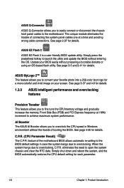
...CPU Parameter Recall) The C.P.R. feature of the motherboard BIOS allows automatic re-setting to the BIOS default settings in Windows environment without the hassle of booting the BIOS. ASUS EZ Flash 2 ASUS EZ Flash 2 is a user-friendly BIOS update utility. ASUS MyLogo 2™ This feature allows you to ...a more colorful and vivid image on your BIOS easily without preparing a bootable diskette or using an OS-based flash utility. ASUS Q-Connector ASUS Q-Connector allows you to easily connect or disconnect the chassis front panel cables to overclock the CPU speed in case the system...
...CPU Parameter Recall) The C.P.R. feature of the motherboard BIOS allows automatic re-setting to the BIOS default settings in Windows environment without the hassle of booting the BIOS. ASUS EZ Flash 2 ASUS EZ Flash 2 is a user-friendly BIOS update utility. ASUS MyLogo 2™ This feature allows you to ...a more colorful and vivid image on your BIOS easily without preparing a bootable diskette or using an OS-based flash utility. ASUS Q-Connector ASUS Q-Connector allows you to easily connect or disconnect the chassis front panel cables to overclock the CPU speed in case the system...

User Manual
Page 23
This chapter lists the hardware setup procedures that you have to perform when installing system components. It includes description of the jumpers and connectors on the motherboard. Chapter 2: 2 Hardware information
This chapter lists the hardware setup procedures that you have to perform when installing system components. It includes description of the jumpers and connectors on the motherboard. Chapter 2: 2 Hardware information
User Manual
Page 24
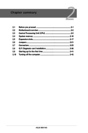
Diagnosis card installation 2-38 2.9 Starting up for the first time 2-41 2.10 Turning off the computer 2-42 ASUS M3N WS Chapter summary 2 2.1 Before you proceed 2-1 2.2 Motherboard overview 2-2 2.3 Central Processing Unit (CPU 2-5 2.4 System memory 2-10 2.5 Expansion slots 2-17 2.6 Jumpers 2-21 2.7 Connectors 2-23 2.8 G.P.
Diagnosis card installation 2-38 2.9 Starting up for the first time 2-41 2.10 Turning off the computer 2-42 ASUS M3N WS Chapter summary 2 2.1 Before you proceed 2-1 2.2 Motherboard overview 2-2 2.3 Central Processing Unit (CPU 2-5 2.4 System memory 2-10 2.5 Expansion slots 2-17 2.6 Jumpers 2-21 2.7 Connectors 2-23 2.8 G.P.

User Manual
Page 25
... to indicate that you should shut down the system and unplug the power cable before removing or plugging in any motherboard component. ASUS M3N WS 2-1 Failure to do so may cause severe damage to avoid touching the ICs on them due to static electricity.... • Hold components by the edges to the motherboard, peripherals, and/or components. Onboard LED The motherboard comes with the component. • Before you install or remove any component, ensure that the ATX...
... to indicate that you should shut down the system and unplug the power cable before removing or plugging in any motherboard component. ASUS M3N WS 2-1 Failure to do so may cause severe damage to avoid touching the ICs on them due to static electricity.... • Hold components by the edges to the motherboard, peripherals, and/or components. Onboard LED The motherboard comes with the component. • Before you install or remove any component, ensure that the ATX...
User Manual
Page 26
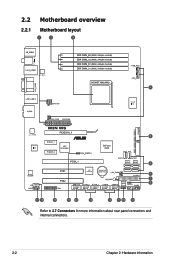
2.2 Motherboard overview 2.2.1 Motherboard layout Refer to 2.7 Connectors for more information about rear panel connectors and internal connectors. 2-2 Chapter 2: Hardware information
2.2 Motherboard overview 2.2.1 Motherboard layout Refer to 2.7 Connectors for more information about rear panel connectors and internal connectors. 2-2 Chapter 2: Hardware information
User Manual
Page 28
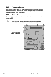
The edge with external ports goes to the chassis. Do not overtighten the screws! Doing so can damage the motherboard. Place this side towards the rear of the chassis as indicated in the correct orientation. 2.2.3 Placement direction When installing the motherboard, make sure that you place it into the chassis in the image below. 2.2.4 Screw holes Place nine (9) screws into the holes indicated by circles to secure the motherboard to the rear part of the chassis 2-4 Chapter 2: Hardware information
The edge with external ports goes to the chassis. Do not overtighten the screws! Doing so can damage the motherboard. Place this side towards the rear of the chassis as indicated in the correct orientation. 2.2.3 Placement direction When installing the motherboard, make sure that you place it into the chassis in the image below. 2.2.4 Screw holes Place nine (9) screws into the holes indicated by circles to secure the motherboard to the rear part of the chassis 2-4 Chapter 2: Hardware information
User Manual
Page 29
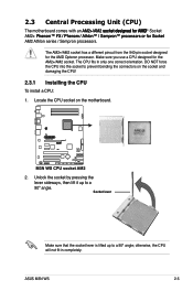
... socket to a 90º angle. Locate the CPU socket on the socket and damaging the CPU! 2.3.1 Installing the CPU To install a CPU: 1. ASUS M3N WS 2-5 2.3 Central Processing Unit (CPU) The motherboard comes with an �A�M�2��+�/A��M�2���s��o��c��k��...
... socket to a 90º angle. Locate the CPU socket on the socket and damaging the CPU! 2.3.1 Installing the CPU To install a CPU: 1. ASUS M3N WS 2-5 2.3 Central Processing Unit (CPU) The motherboard comes with an �A�M�2��+�/A��M�2���s��o��c��k��...
User Manual
Page 31
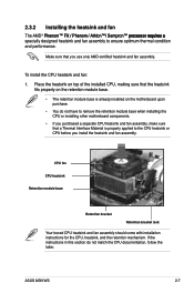
... module base when installing the CPU or installing other motherboard components. • If you purchased a separate CPU heatsink and fan assembly, make sure that a Thermal Interface Material is properly applied to ensure optimum thermal condition and performance. ASUS M3N WS 2-7 CPU fan CPU heatsink Retention module base Retention... the heatsink fits properly on the retention module base. • The retention module base is already installed on the motherboard upon purchase. • You do not match the CPU documentation, follow the latter. To install the CPU heatsink and fan: 1.
... module base when installing the CPU or installing other motherboard components. • If you purchased a separate CPU heatsink and fan assembly, make sure that a Thermal Interface Material is properly applied to ensure optimum thermal condition and performance. ASUS M3N WS 2-7 CPU fan CPU heatsink Retention module base Retention... the heatsink fits properly on the retention module base. • The retention module base is already installed on the motherboard upon purchase. • You do not match the CPU documentation, follow the latter. To install the CPU heatsink and fan: 1.
User Manual
Page 33
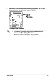
When the fan and heatsink assembly is in place, connect the CPU fan cable to the connector on the motherboard labeled CPU_FAN. • Do not forget to plug this connector. • This connector is backward compatible with 3-pin CPU fans . Hardware monitoring errors can occur if you fail to connect the CPU fan connector! ASUS M3N WS 2-9 5.
When the fan and heatsink assembly is in place, connect the CPU fan cable to the connector on the motherboard labeled CPU_FAN. • Do not forget to plug this connector. • This connector is backward compatible with 3-pin CPU fans . Hardware monitoring errors can occur if you fail to connect the CPU fan connector! ASUS M3N WS 2-9 5.
User Manual
Page 34
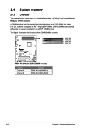
A DDR2 module has the same physical dimensions as a DDR DIMM but has a 240-pin footprint compared to prevent installation on a DDR DIMM socket. DDR2 DIMMs are notched differently to the 184-pin DDR DIMM. The figure illustrates the location of the DDR2 DIMM sockets: Channel Channel A Channel B Sockets DIMM_A1 and DIMM_A2 DIMM_B1 and DIMM_B2 2-10 Chapter 2: Hardware information 2.4 System memory 2.4.1 Overview The motherboard comes with four Double Data Rate 2 (DDR2) Dual Inline Memory Modules (DIMM) sockets.
A DDR2 module has the same physical dimensions as a DDR DIMM but has a 240-pin footprint compared to prevent installation on a DDR DIMM socket. DDR2 DIMMs are notched differently to the 184-pin DDR DIMM. The figure illustrates the location of the DDR2 DIMM sockets: Channel Channel A Channel B Sockets DIMM_A1 and DIMM_A2 DIMM_B1 and DIMM_B2 2-10 Chapter 2: Hardware information 2.4 System memory 2.4.1 Overview The motherboard comes with four Double Data Rate 2 (DDR2) Dual Inline Memory Modules (DIMM) sockets.


