
User Guide
Page 7
... from the electrical outlet before relocating the system. • When adding or removing devices to or from the system, ensure that your power supply is broken, do not try to the correct voltage in any damage, contact your dealer immediately. • To avoid short circuits, ...the product in your local power company. • If the power supply is set to fix it , carefully read all the manuals that all cables are correctly connected and the power cables are using an adapter or extension cord. If possible, disconnect all power cables from the motherboard, ensure that came with...
... from the electrical outlet before relocating the system. • When adding or removing devices to or from the system, ensure that your power supply is broken, do not try to the correct voltage in any damage, contact your dealer immediately. • To avoid short circuits, ...the product in your local power company. • If the power supply is set to fix it , carefully read all the manuals that all cables are correctly connected and the power cables are using an adapter or extension cord. If possible, disconnect all power cables from the motherboard, ensure that came with...

User Guide
Page 10
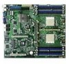
...Power Requirement ATX power supply (with 24-pin and 8-pin 12 V plugs) ATX 12 V 2.0 compliant (continued on board; RAID 0, RAID 1, and RAID 1E configurations (SCSI model only) Dual LAN 2 x BROADCOM® BCM5721 Gigabit PCI-E LAN controllers USB 2 x USB 2.0 ports (on the rear panel) 1 x USB 2.0 connector (on the next page) x K8N-DRE... ECC 400/333/266 MHz DDR memory modules Supports up to 32 GB system memory (Note: Tested only up to 16 GB on this motherboard due to 2 GB DDR availability) 1 x PCI Express x16 slot 1 x PCI slot NVIDIA® nForce Professional 2200 chipset supports: -...
...Power Requirement ATX power supply (with 24-pin and 8-pin 12 V plugs) ATX 12 V 2.0 compliant (continued on board; RAID 0, RAID 1, and RAID 1E configurations (SCSI model only) Dual LAN 2 x BROADCOM® BCM5721 Gigabit PCI-E LAN controllers USB 2 x USB 2.0 ports (on the rear panel) 1 x USB 2.0 connector (on the next page) x K8N-DRE... ECC 400/333/266 MHz DDR memory modules Supports up to 32 GB system memory (Note: Tested only up to 16 GB on this motherboard due to 2 GB DDR availability) 1 x PCI Express x16 slot 1 x PCI slot NVIDIA® nForce Professional 2200 chipset supports: -...

User Guide
Page 11
K8N-DRE specifications summary Internal connectors Form Factor Support CD contents 1 x Floppy disk drive connector 2 x IDE connectors 4 x Serial ATA connectors 1 x 68-pin SCSI connector (SCSI models only) 6 x Front fan connector 4 x Rear fan connector 1 x 24-pin ATX power connector 1 x 8-pin ATX 12 V power connector 1 x Power supply SMBUS connector 1 x Serial port (COM2) 1 x USB 2.0 connector for 2 additional USB 2.0 ports 1 x SMBus header for...
K8N-DRE specifications summary Internal connectors Form Factor Support CD contents 1 x Floppy disk drive connector 2 x IDE connectors 4 x Serial ATA connectors 1 x 68-pin SCSI connector (SCSI models only) 6 x Front fan connector 4 x Rear fan connector 1 x 24-pin ATX power connector 1 x 8-pin ATX 12 V power connector 1 x Power supply SMBUS connector 1 x Serial port (COM2) 1 x USB 2.0 connector for 2 additional USB 2.0 ports 1 x SMBus header for...

User Guide
Page 21
... K8N-DRE Standby power LED SB_PWR1 ON Standby Power OFF Powered Off ASUS K8N-DRE 2-1 See "10. Standby power LED (SB_PWR1) The motherboard comes with the component. • Before you uninstall any motherboard settings. • Make sure that your power supply unit (PSU) can provide at least the minimum power ... processor is a reminder that the ATX power supply is ON, in sleep mode, or in any motherboard component. 2. This is not installed properly in the bag that came with a green standby power LED that lights up to the motherboard, peripherals, and/or components.
... K8N-DRE Standby power LED SB_PWR1 ON Standby Power OFF Powered Off ASUS K8N-DRE 2-1 See "10. Standby power LED (SB_PWR1) The motherboard comes with the component. • Before you uninstall any motherboard settings. • Make sure that your power supply unit (PSU) can provide at least the minimum power ... processor is a reminder that the ATX power supply is ON, in sleep mode, or in any motherboard component. 2. This is not installed properly in the bag that came with a green standby power LED that lights up to the motherboard, peripherals, and/or components.

User Guide
Page 28
... and rear fan connectors (3-pin FRNT_FAN1, FRNT_FAN2, FRNT_FAN3, FRNT_FAN4, FRNT_FAN5, FRNT_FAN6, REAR-FAN1, REAR_FAN2, REAR_FAN3, REAR_FAN4) 7. Backplane SMBus connector (6-1 pin FPSMB) 8. ATX power connectors (24-pin ATXPWR1, 8-pin ATX12V1) 11. Power supply SMBus connector (5-pin PSUSMB1) 12. Storage add-in card activity LED connector (4-pin HDLED1) 6. System panel connector (20-pin PANEL1) Page 2-23...
... and rear fan connectors (3-pin FRNT_FAN1, FRNT_FAN2, FRNT_FAN3, FRNT_FAN4, FRNT_FAN5, FRNT_FAN6, REAR-FAN1, REAR_FAN2, REAR_FAN3, REAR_FAN4) 7. Backplane SMBus connector (6-1 pin FPSMB) 8. ATX power connectors (24-pin ATXPWR1, 8-pin ATX12V1) 11. Power supply SMBus connector (5-pin PSUSMB1) 12. Storage add-in card activity LED connector (4-pin HDLED1) 6. System panel connector (20-pin PANEL1) Page 2-23...

User Guide
Page 35
... DO NOT force a DIMM into the socket until the retaining clips snap back in only one direction. Remove the DIMM from the socket. ASUS K8N-DRE 2-15 The DIMM might get damaged when it fits in place and the DIMM is keyed with a notch so that it flips out with...to both the motherboard and the components. 1. Failure to do so may cause severe damage to unlock the DIMM. 1 1 DDR DIMM notch Support the DIMM lightly with extra force. 2. Firmly insert the DIMM into a socket to remove a DIMM. 2 1. 2.4.3 Installing a DIMM Make sure to unplug the power supply before adding ...
... DO NOT force a DIMM into the socket until the retaining clips snap back in only one direction. Remove the DIMM from the socket. ASUS K8N-DRE 2-15 The DIMM might get damaged when it fits in place and the DIMM is keyed with a notch so that it flips out with...to both the motherboard and the components. 1. Failure to do so may cause severe damage to unlock the DIMM. 1 1 DDR DIMM notch Support the DIMM lightly with extra force. 2. Firmly insert the DIMM into a socket to remove a DIMM. 2 1. 2.4.3 Installing a DIMM Make sure to unplug the power supply before adding ...
User Guide
Page 39
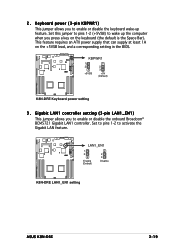
... feature requires an ATX power supply that can supply at least 1A on the keyboard (the default is the Space Bar). Gigabit LAN1 controller setting (3-pin LAN1_EN1) This jumper allows you to wake up feature. K8N-DRE ® LAN1_EN1 1 2 Enable (Default) 2 3 Disable K8N-DRE LAN1_EN1 setting ASUS K8N-DRE 2-19 K8N-DRE ® KBPWR1 1 2 +5VSB 2 3 +5V (Default) K8N-DRE Keyboard power setting 3 . Keyboard power (3-pin KBPWR1) This...
... feature requires an ATX power supply that can supply at least 1A on the keyboard (the default is the Space Bar). Gigabit LAN1 controller setting (3-pin LAN1_EN1) This jumper allows you to wake up feature. K8N-DRE ® LAN1_EN1 1 2 Enable (Default) 2 3 Disable K8N-DRE LAN1_EN1 setting ASUS K8N-DRE 2-19 K8N-DRE ® KBPWR1 1 2 +5VSB 2 3 +5V (Default) K8N-DRE Keyboard power setting 3 . Keyboard power (3-pin KBPWR1) This...

User Guide
Page 48
... K8N-DRE ® +3 Volts -12 Volts Ground PSON# Ground Ground Ground -5 Volts +5 Volts +5 Volts +5 Volts Ground K8N-DRE ATX Power connectors +3 Volts +3 Volts Ground +5 Volts Ground +5 Volts Ground Power OK +5V Standby +12 Volts +12 Volts +3 Volts 12V GND 12V GND 12V GND 12V GND For Power Supply with more power-consuming devices. See the table below for an ATX power supply plugs...
... K8N-DRE ® +3 Volts -12 Volts Ground PSON# Ground Ground Ground -5 Volts +5 Volts +5 Volts +5 Volts Ground K8N-DRE ATX Power connectors +3 Volts +3 Volts Ground +5 Volts Ground +5 Volts Ground Power OK +5V Standby +12 Volts +12 Volts +3 Volts 12V GND 12V GND 12V GND 12V GND For Power Supply with more power-consuming devices. See the table below for an ATX power supply plugs...

User Guide
Page 49
...# ERROR# PINIT# SLIN# GND GND GND GND GND GND GND GND K8N-DRE Parallel port connector ASUS K8N-DRE 2-29 Devices communicate with an SMBus host and/or other SMBus devices using the SMBus interface. K8N-DRE ® PSUSMB1 PSU_I2CCLK PSU_I2CDATA NC GND +3.3V Remote Sense K8N-DRE Power supply SMBus connector 12. Parallel port connector (26-1 pin LPT1) This connector...
...# ERROR# PINIT# SLIN# GND GND GND GND GND GND GND GND K8N-DRE Parallel port connector ASUS K8N-DRE 2-29 Devices communicate with an SMBus host and/or other SMBus devices using the SMBus interface. K8N-DRE ® PSUSMB1 PSU_I2CCLK PSU_I2CDATA NC GND +3.3V Remote Sense K8N-DRE Power supply SMBus connector 12. Parallel port connector (26-1 pin LPT1) This connector...
User Guide
Page 55
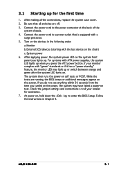
... last device on , hold down the key to enter the BIOS Setup. ASUS K8N-DRE 3-1 After making all switches are running, the BIOS beeps or additional messages appear on test. Connect the power cord to a power outlet that all the connections, replace the system case cover. 2. Monitor ...3.1 Starting up for assistance. 7. At power on the chain) c. Connect the power cord to the power connector at the back of the system chassis. 4. External SCSI devices (starting with ATX power supplies, the system LED lights up when you turned on the power, the system may light up or switch...
... last device on , hold down the key to enter the BIOS Setup. ASUS K8N-DRE 3-1 After making all switches are running, the BIOS beeps or additional messages appear on test. Connect the power cord to a power outlet that all the connections, replace the system case cover. 2. Monitor ...3.1 Starting up for assistance. 7. At power on the chain) c. Connect the power cord to the power connector at the back of the system chassis. 4. External SCSI devices (starting with ATX power supplies, the system LED lights up when you turned on the power, the system may light up or switch...

User Guide
Page 84
...on the keyboard to turn on AC Power Loss [Power Off] When set to [Enabled], the system will reboot after an AC power loss. This feature requires an ATX power supply that provides at least 1A on the +5VSB lead. This feature requires an ATX power supply that provides at least 1A on the ...+5VSB lead. When set to Power Off, the system goes into either off ...
...on the keyboard to turn on AC Power Loss [Power Off] When set to [Enabled], the system will reboot after an AC power loss. This feature requires an ATX power supply that provides at least 1A on the +5VSB lead. This feature requires an ATX power supply that provides at least 1A on the ...+5VSB lead. When set to Power Off, the system goes into either off ...


