
User Guide
Page 4
... off the computer 3-2 3.2.1 Using the OS shut down function 3-2 3.2.2 Using the dual function power switch 3-2 Chapter 4: BIOS setup 4.1 Managing and updating your BIOS 4-1 4.1.1 Creating a bootable floppy disk 4-1 4.1.2 AFUDOS utility 4-2 4.1.3 ASUS CrashFree BIOS 2 utility 4-5 4.1.4 ASUS Update utility 4-7 4.2 BIOS setup program 4-10 4.2.1 BIOS menu screen 4-11 4.2.2 Menu bar 4-11 4.2.3 Navigation keys 4-11 4.2.4 Menu items 4-12 4.2.5 Sub-menu items 4-12...
... off the computer 3-2 3.2.1 Using the OS shut down function 3-2 3.2.2 Using the dual function power switch 3-2 Chapter 4: BIOS setup 4.1 Managing and updating your BIOS 4-1 4.1.1 Creating a bootable floppy disk 4-1 4.1.2 AFUDOS utility 4-2 4.1.3 ASUS CrashFree BIOS 2 utility 4-5 4.1.4 ASUS Update utility 4-7 4.2 BIOS setup program 4-10 4.2.1 BIOS menu screen 4-11 4.2.2 Menu bar 4-11 4.2.3 Navigation keys 4-11 4.2.4 Menu items 4-12 4.2.5 Sub-menu items 4-12...
User Guide
Page 5
...Chapter 5: RAID configuration 5.1 Setting up RAID 5-1 5.1.1 RAID definitions 5-1 5.1.2 Installing hard disk drives 5-2 5.1.3 RAID configuration utility 5-2 5.2 NVIDIA® RAID configurations 5-3 5.2.1 Setting the BIOS RAID items 5-3 5.2.2 Entering the NVIDIA® RAID Utility 5-4 5.2.3 Creating a RAID 0 set (Stripe 5-5 5.2.4 Creating a RAID 1 set (Mirror 5-7 5.2.5 Rebuilding a RAID ...Support CD information 6-4 6.4.1 Running the support CD 6-4 6.4.2 Drivers menu 6-5 6.4.3 Management Software 6-6 6.4.4 Utilities 6-7 Appendix: Reference information A.1 K8N-DRE block diagram A-1 v
...Chapter 5: RAID configuration 5.1 Setting up RAID 5-1 5.1.1 RAID definitions 5-1 5.1.2 Installing hard disk drives 5-2 5.1.3 RAID configuration utility 5-2 5.2 NVIDIA® RAID configurations 5-3 5.2.1 Setting the BIOS RAID items 5-3 5.2.2 Entering the NVIDIA® RAID Utility 5-4 5.2.3 Creating a RAID 0 set (Stripe 5-5 5.2.4 Creating a RAID 1 set (Mirror 5-7 5.2.5 Rebuilding a RAID ...Support CD information 6-4 6.4.1 Running the support CD 6-4 6.4.2 Drivers menu 6-5 6.4.3 Management Software 6-6 6.4.4 Utilities 6-7 Appendix: Reference information A.1 K8N-DRE block diagram A-1 v
User Guide
Page 8
... 1: Product introduction This chapter describes the features of shutting down the system. • Chapter 4: BIOS setup Tells how to when configuring the motherboard. viii Where to find more information Refer to the ASUS contact information. 2. These documents are not part of the BIOS parameters are also provided. • Chapter 5: RAID configuration Provides information on...
... 1: Product introduction This chapter describes the features of shutting down the system. • Chapter 4: BIOS setup Tells how to when configuring the motherboard. viii Where to find more information Refer to the ASUS contact information. 2. These documents are not part of the BIOS parameters are also provided. • Chapter 5: RAID configuration Provides information on...

User Guide
Page 10
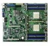
...RAID 0, RAID 1, RAID 1+0, and JBOD configurations LSI 1020A SCSI RAID controller supports: - K8N-DRE specifications summary CPU Chipset System Bus Memory Expansion slots Storage Dual Socket 940 for AMD Opteron&#...ASUS Q-Fan 2 ASUS CrashFree BIOS 2 ASUS MyLogo2 Rear panel 1 x Serial port (COM1) 2 x LAN (RJ-45) port 1 x VGA port 2 x USB 2.0 ports 1 x PS/2 keyboard port 1 x PS/2 mouse port BIOS features 8 Mb Flash ROM, AMI BIOS, PnP, DMI2.0, WfM2.0, SM BIOS 2.3 Power Requirement ATX power supply (with 24-pin and 8-pin 12 V plugs) ATX 12 V 2.0 compliant (continued on this motherboard...
...RAID 0, RAID 1, RAID 1+0, and JBOD configurations LSI 1020A SCSI RAID controller supports: - K8N-DRE specifications summary CPU Chipset System Bus Memory Expansion slots Storage Dual Socket 940 for AMD Opteron&#...ASUS Q-Fan 2 ASUS CrashFree BIOS 2 ASUS MyLogo2 Rear panel 1 x Serial port (COM1) 2 x LAN (RJ-45) port 1 x VGA port 2 x USB 2.0 ports 1 x PS/2 keyboard port 1 x PS/2 mouse port BIOS features 8 Mb Flash ROM, AMI BIOS, PnP, DMI2.0, WfM2.0, SM BIOS 2.3 Power Requirement ATX power supply (with 24-pin and 8-pin 12 V plugs) ATX 12 V 2.0 compliant (continued on this motherboard...
User Guide
Page 18
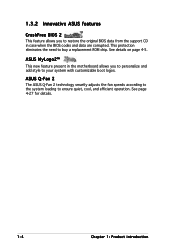
... chip. See page 4-27 for details. 1-4 Chapter 1: Product introduction ASUS MyLogo2™ This new feature present in the motherboard allows you to restore the original BIOS data from the support CD in case when the BIOS codes and data are corrupted. 1.3.2 Innovative ASUS features CrashFree BIOS 2 This feature allows you to personalize and add style to...
... chip. See page 4-27 for details. 1-4 Chapter 1: Product introduction ASUS MyLogo2™ This new feature present in the motherboard allows you to restore the original BIOS data from the support CD in case when the BIOS codes and data are corrupted. 1.3.2 Innovative ASUS features CrashFree BIOS 2 This feature allows you to personalize and add style to...

User Guide
Page 27
... 1. BIOS recovery setting (3-pin RECOVERY1) 7. CPU sockets 2. Keyboard power (3-pin KBPWR1) 3. Gigabit LAN2 controller setting (3-pin LAN2_EN1) 5. DDR DIMM sockets 3. PS/2 keyboard port (purple) 3. USB 2.0 ports 1 and 2 4. LAN 2 (RJ-45) port Page 2-9 2-12 2-17 Page 2-18 2-19 2-19 2-20 2-20 2-21 2-21 Page 2-22 2-22 2-22 2-22 2-22 2-22 2-22 ASUS K8N-DRE 2-7 SCSI...
... 1. BIOS recovery setting (3-pin RECOVERY1) 7. CPU sockets 2. Keyboard power (3-pin KBPWR1) 3. Gigabit LAN2 controller setting (3-pin LAN2_EN1) 5. DDR DIMM sockets 3. PS/2 keyboard port (purple) 3. USB 2.0 ports 1 and 2 4. LAN 2 (RJ-45) port Page 2-9 2-12 2-17 Page 2-18 2-19 2-19 2-20 2-20 2-21 2-21 Page 2-22 2-22 2-22 2-22 2-22 2-22 2-22 ASUS K8N-DRE 2-7 SCSI...

User Guide
Page 36
... slot on the riser card slot. 6. Remove the system unit cover (if your motherboard is completely seated on the riser card and press firmly until the riser card is completely seated on the system and change the necessary BIOS settings, if any. Keep the screw for the expansion card. 2-16 Chapter 2: Hardware...
... slot on the riser card slot. 6. Remove the system unit cover (if your motherboard is completely seated on the riser card and press firmly until the riser card is completely seated on the system and change the necessary BIOS settings, if any. Keep the screw for the expansion card. 2-16 Chapter 2: Hardware...
User Guide
Page 38
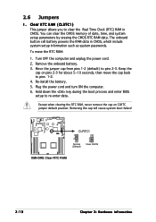
...1-2. 4. You can clear the CMOS memory of date, time, and system setup parameters by erasing the CMOS RTC RAM data. K8N-DRE ® CLRTC1 1 2 Normal (Default) 2 3 Clear CMOS K8N-DRE Clear RTC RAM 2-18 Chapter 2: Hardware information 2.6 Jumpers 1. The onboard button cell battery powers the RAM data in CMOS. Remove... pins 2-3 for about 5~10 seconds, then move the cap back to pins 2-3. Hold down the key during the boot process and enter BIOS setup to clear the Real Time Clock (RTC) RAM in CMOS, which include system setup information such as system passwords. Clear RTC RAM ...
...1-2. 4. You can clear the CMOS memory of date, time, and system setup parameters by erasing the CMOS RTC RAM data. K8N-DRE ® CLRTC1 1 2 Normal (Default) 2 3 Clear CMOS K8N-DRE Clear RTC RAM 2-18 Chapter 2: Hardware information 2.6 Jumpers 1. The onboard button cell battery powers the RAM data in CMOS. Remove... pins 2-3 for about 5~10 seconds, then move the cap back to pins 2-3. Hold down the key during the boot process and enter BIOS setup to clear the Real Time Clock (RTC) RAM in CMOS, which include system setup information such as system passwords. Clear RTC RAM ...
User Guide
Page 39
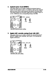
... controller setting (3-pin LAN1_EN1) This jumper allows you press a key on the +5VSB lead, and a corresponding setting in the BIOS. K8N-DRE ® LAN1_EN1 1 2 Enable (Default) 2 3 Disable K8N-DRE LAN1_EN1 setting ASUS K8N-DRE 2-19 This feature requires an ATX power supply that can supply at least 1A on the keyboard (the default is the Space Bar). Keyboard power...
... controller setting (3-pin LAN1_EN1) This jumper allows you press a key on the +5VSB lead, and a corresponding setting in the BIOS. K8N-DRE ® LAN1_EN1 1 2 Enable (Default) 2 3 Disable K8N-DRE LAN1_EN1 setting ASUS K8N-DRE 2-19 This feature requires an ATX power supply that can supply at least 1A on the keyboard (the default is the Space Bar). Keyboard power...

User Guide
Page 41
... cap from pins 2-3 to pins 1-2. 8.Reboot your original BIOS from a floppy disk in case the BIOS codes and data are corrupted. Set to pins 1-2 to re-enter data. K8N-DRE ® RECOVERY1 1 2 Normal (Default) 2 3 BIOS recovery K8N-DRE BIOS recovery setting 7 . K8N-DRE ® K8N-DRE VGA setting ASUS K8N-DRE VGA_EN1 1 2 Enable (Default) 2 3 Disable 2-21 6. BIOS Recovery (3-pin RECOVERY1) This jumper allows you to recover...
... cap from pins 2-3 to pins 1-2. 8.Reboot your original BIOS from a floppy disk in case the BIOS codes and data are corrupted. Set to pins 1-2 to re-enter data. K8N-DRE ® RECOVERY1 1 2 Normal (Default) 2 3 BIOS recovery K8N-DRE BIOS recovery setting 7 . K8N-DRE ® K8N-DRE VGA setting ASUS K8N-DRE VGA_EN1 1 2 Enable (Default) 2 3 Disable 2-21 6. BIOS Recovery (3-pin RECOVERY1) This jumper allows you to recover...

User Guide
Page 51
System panel connector (20-pin PANEL1) This connector supports several chassis-mounted functions. ASUS K8N-DRE 2-31 Connect the HDD Activity LED cable to light up. • System warning speaker (Orange 4-pin SPKROUT) This 4-pin connector is installed, the read from ... the system power. If an optional SCSI or SATA add-in card is for the HDD Activity LED. The speaker allows you turn on the BIOS settings. Pressing the power button turns the system ON or puts the system in sleep mode. • Hard disk drive activity (Red 2-pin HDDLED) This...
System panel connector (20-pin PANEL1) This connector supports several chassis-mounted functions. ASUS K8N-DRE 2-31 Connect the HDD Activity LED cable to light up. • System warning speaker (Orange 4-pin SPKROUT) This 4-pin connector is installed, the read from ... the system power. If an optional SCSI or SATA add-in card is for the HDD Activity LED. The speaker allows you turn on the BIOS settings. Pressing the power button turns the system ON or puts the system in sleep mode. • Hard disk drive activity (Red 2-pin HDDLED) This...
User Guide
Page 55
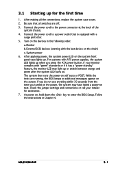
... button. Follow the instructions in the following order: a. After making all switches are running, the BIOS beeps or additional messages appear on the screen. Be sure that is equipped with ATX power supplies, the system LED lights up . For systems with a surge protector. 5. Check the jumper settings and connections or call... between orange and green after the system LED turns on. At power on self tests or POST. If your retailer for the first time 1. ASUS K8N-DRE 3-1 Turn on the devices in Chapter 4. The system then runs the power-on , hold down the key to enter the...
... button. Follow the instructions in the following order: a. After making all switches are running, the BIOS beeps or additional messages appear on the screen. Be sure that is equipped with ATX power supplies, the system LED lights up . For systems with a surge protector. 5. Check the jumper settings and connections or call... between orange and green after the system LED turns on. At power on self tests or POST. If your retailer for the first time 1. ASUS K8N-DRE 3-1 Turn on the devices in Chapter 4. The system then runs the power-on , hold down the key to enter the...
User Guide
Page 56
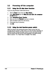
... the P l a n n e d check box is ON, pressing the power switch for less than four seconds lets the system enter the soft-off mode regardless of the BIOS setting. Select shutdown option from the W h a t d o y o u w a n t t h e c o m p u t e r t o d o ? If necessary, key in Chapter 4 for more than four seconds puts the system to sleep...Server: 1. Select S h u t d o w n E v e n t T r a c k e r. 4. Pressing the power switch for details. 3-2 Chapter 3: Powering up Select S h u t D o w n from the list box. 6. 3.2 Powering off mode, depending on the BIOS setting. list box. 3.
... the P l a n n e d check box is ON, pressing the power switch for less than four seconds lets the system enter the soft-off mode regardless of the BIOS setting. Select shutdown option from the W h a t d o y o u w a n t t h e c o m p u t e r t o d o ? If necessary, key in Chapter 4 for more than four seconds puts the system to sleep...Server: 1. Select S h u t d o w n E v e n t T r a c k e r. 4. Pressing the power switch for details. 3-2 Chapter 3: Powering up Select S h u t D o w n from the list box. 6. 3.2 Powering off mode, depending on the BIOS setting. list box. 3.
User Guide
Page 57
This chapter tells how to change the system settings through the BIOS Setup menus. Detailed descriptions of the BIOS parameters are also provided. 4 BIOS setup
This chapter tells how to change the system settings through the BIOS Setup menus. Detailed descriptions of the BIOS parameters are also provided. 4 BIOS setup
User Guide
Page 58
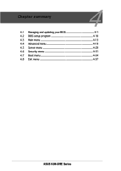
Chapter summary 4 4.1 Managing and updating your BIOS 4-1 4.2 BIOS setup program 4-10 4.3 Main menu 4-13 4.4 Advanced menu 4-19 4.5 Server menu 4-29 4.6 Security menu 4-31 4.7 Boot menu 4-34 4.8 Exit menu 4-37 ASUS K8N-DRE Series
Chapter summary 4 4.1 Managing and updating your BIOS 4-1 4.2 BIOS setup program 4-10 4.3 Main menu 4-13 4.4 Advanced menu 4-19 4.5 Server menu 4-29 4.6 Security menu 4-31 4.7 Boot menu 4-34 4.8 Exit menu 4-37 ASUS K8N-DRE Series
User Guide
Page 59
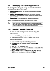
... C r e a t e a n M S - A S U S C r a s h F r e e B I O S 2 (Updates the BIOS using the ASUS Update or AFUDOS utilities. 4.1.1 Creating a bootable floppy disk 1. b. Insert a 1.44 MB floppy disk to the floppy disk drive. Select the 3 1/2 Floppy Drive icon. D O S s t a r t u p d i s k from the format options field, then click S t a r t. Copy the original motherboard BIOS using a bootable floppy disk or the motherboard support CD when the BIOS file fails or...
... C r e a t e a n M S - A S U S C r a s h F r e e B I O S 2 (Updates the BIOS using the ASUS Update or AFUDOS utilities. 4.1.1 Creating a bootable floppy disk 1. b. Insert a 1.44 MB floppy disk to the floppy disk drive. Select the 3 1/2 Floppy Drive icon. D O S s t a r t u p d i s k from the format options field, then click S t a r t. Copy the original motherboard BIOS using a bootable floppy disk or the motherboard support CD when the BIOS file fails or...
User Guide
Page 60
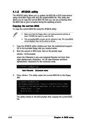
Copy the AFUDOS utility (afudos.exe) from the motherboard support CD to the bootable floppy disk you can use as shown. 1. The utility copies the current BIOS file to file...... This utility also allows you to copy the current BIOS file that the floppy disk is not write-protected .... A:\>afudos /oOLDBIOS1.rom Main filename Extension name 3. Version 1.19(ASUS V2.07(03.11.24BB)) Copyright (C) 2002 American Megatrends, Inc. All rights reserved. Press . 4.1.2 AFUDOS utility The AFUDOS utility allows you to update the BIOS file in DOS mode, then at least 1024KB free space to save...
Copy the AFUDOS utility (afudos.exe) from the motherboard support CD to the bootable floppy disk you can use as shown. 1. The utility copies the current BIOS file to file...... This utility also allows you to copy the current BIOS file that the floppy disk is not write-protected .... A:\>afudos /oOLDBIOS1.rom Main filename Extension name 3. Version 1.19(ASUS V2.07(03.11.24BB)) Copyright (C) 2002 American Megatrends, Inc. All rights reserved. Press . 4.1.2 AFUDOS utility The AFUDOS utility allows you to update the BIOS file in DOS mode, then at least 1024KB free space to save...

User Guide
Page 61
... /i[filename] where [filename] is the latest or the original BIOS file on a piece of paper. done Reading flash ...... Visit the ASUS website (www.asus.com) and download the latest BIOS file for the motherboard. The utility verifies the file and starts updating the BIOS. Version 1.19(ASUS V2.07(03.11.24BB)) Copyright (C) 2002 American Megatrends, Inc...
... /i[filename] where [filename] is the latest or the original BIOS file on a piece of paper. done Reading flash ...... Visit the ASUS website (www.asus.com) and download the latest BIOS file for the motherboard. The utility verifies the file and starts updating the BIOS. Version 1.19(ASUS V2.07(03.11.24BB)) Copyright (C) 2002 American Megatrends, Inc...
User Guide
Page 62
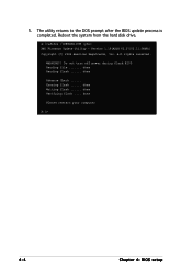
done Advance Check ...... done Verifying flash .... done Please restart your computer A:\> 4-4 Chapter 4: BIOS setup Version 1.19(ASUS V2.07(03.11.24BB)) Copyright (C) 2002 American Megatrends, Inc. done Reading flash ...... The utility returns to the DOS prompt after the BIOS update process is completed. All rights reserved. done Writing flash ...... Do not turn off power during flash BIOS Reading file ....... Reboot the system from the hard disk drive. Erasing flash ...... 5. A:\>afudos /iK8NDRE.ROM /pbnc AMI Firmware Update Utility - WARNING!!
done Advance Check ...... done Verifying flash .... done Please restart your computer A:\> 4-4 Chapter 4: BIOS setup Version 1.19(ASUS V2.07(03.11.24BB)) Copyright (C) 2002 American Megatrends, Inc. done Reading flash ...... The utility returns to the DOS prompt after the BIOS update process is completed. All rights reserved. done Writing flash ...... Do not turn off power during flash BIOS Reading file ....... Reboot the system from the hard disk drive. Erasing flash ...... 5. A:\>afudos /iK8NDRE.ROM /pbnc AMI Firmware Update Utility - WARNING!!
User Guide
Page 63
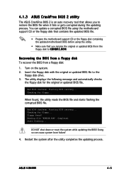
...original or updated BIOS file. Doing so can update a corrupted BIOS file using the motherboard support CD or the floppy disk that contains the updated BIOS file. • Prepare the motherboard support CD or the floppy disk containing the updated motherboard BIOS before using ... utility reads the BIOS file and starts flashing the corrupted BIOS file. Starting BIOS recovery... Completed. ASUS K8NDRE 4-5 Reading file "K8NDRE.ROM". Start flashing... 4.1.3 ASUS CrashFree BIOS 2 utility The ASUS CrashFree BIOS 2 is an auto recovery tool that you to restore the BIOS file when it ...
...original or updated BIOS file. Doing so can update a corrupted BIOS file using the motherboard support CD or the floppy disk that contains the updated BIOS file. • Prepare the motherboard support CD or the floppy disk containing the updated motherboard BIOS before using ... utility reads the BIOS file and starts flashing the corrupted BIOS file. Starting BIOS recovery... Completed. ASUS K8NDRE 4-5 Reading file "K8NDRE.ROM". Start flashing... 4.1.3 ASUS CrashFree BIOS 2 utility The ASUS CrashFree BIOS 2 is an auto recovery tool that you to restore the BIOS file when it ...


