User Manual
Page 1
R HX97 Pentium® Motherboard USER'S MANUAL
R HX97 Pentium® Motherboard USER'S MANUAL

User Manual
Page 4
...SOFTWARE 32 Support Software 32 Flash Memory Writer Utility 32 Main Menu 32 Advanced Features Menu 33 Managing & Updating your Motherboard's BIOS 34 6. FEATURES 8 Features of the ASUS HX97 Motherboard 8 Parts of the ASUS HX97 Motherboard 10 Installation Steps 12 1. System Memory (SIMM 17 SIMM Memory Installation 18 3. Expansion Cards 20 Expansion Card Installation...50 Supervisor Password and User Password 51 IDE HDD Auto Detection 52 Save and Exit Setup 53 Exit Without Saving 53 4 ASUS HX97 User's Manual External Connectors 22 Power Connection Procedures 31 IV.
...SOFTWARE 32 Support Software 32 Flash Memory Writer Utility 32 Main Menu 32 Advanced Features Menu 33 Managing & Updating your Motherboard's BIOS 34 6. FEATURES 8 Features of the ASUS HX97 Motherboard 8 Parts of the ASUS HX97 Motherboard 10 Installation Steps 12 1. System Memory (SIMM 17 SIMM Memory Installation 18 3. Expansion Cards 20 Expansion Card Installation...50 Supervisor Password and User Password 51 IDE HDD Auto Detection 52 Save and Exit Setup 53 Exit Without Saving 53 4 ASUS HX97 User's Manual External Connectors 22 Power Connection Procedures 31 IV.

User Manual
Page 7
... This manual is complete. Introduction: Manual information and checklist II. IV. VI. ASUS PCI-SC200: Installation of software drivers and utilities. DOS/Win3.1x: Audio Software Manual (ASUS I-A16C Audio bundle) Item Checklist Please check that your retailer. √ The ASUS HX97 motherboard √ 2 serial port ribbon cables attached to a mounting bracket √ 1 parallel ribbon...
... This manual is complete. Introduction: Manual information and checklist II. IV. VI. ASUS PCI-SC200: Installation of software drivers and utilities. DOS/Win3.1x: Audio Software Manual (ASUS I-A16C Audio bundle) Item Checklist Please check that your retailer. √ The ASUS HX97 motherboard √ 2 serial port ribbon cables attached to a mounting bracket √ 1 parallel ribbon...

User Manual
Page 8
... Module for the demanding PC user who wants a simple design with two connectors that supports auto detection of the ASUS HX97 Motherboard The ASUS HX97 is carefully designed for wireless connections. Two floppy drives of compatibility. (Requires DMI-enabled components.) (See section ... FEATURES (Specifications) II. FEATURES Features of hard drives, PS/2 mouse, and Plug and Play devices to support optional ASUS SCSI controller cards. 8 ASUS HX97 User's Manual Supports Japanese standard "Floppy 3 mode" (3.5" 1.2MB). • Desktop Management Interface (DMI): Supports DMI ...
... Module for the demanding PC user who wants a simple design with two connectors that supports auto detection of the ASUS HX97 Motherboard The ASUS HX97 is carefully designed for wireless connections. Two floppy drives of compatibility. (Requires DMI-enabled components.) (See section ... FEATURES (Specifications) II. FEATURES Features of hard drives, PS/2 mouse, and Plug and Play devices to support optional ASUS SCSI controller cards. 8 ASUS HX97 User's Manual Supports Japanese standard "Floppy 3 mode" (3.5" 1.2MB). • Desktop Management Interface (DMI): Supports DMI ...
User Manual
Page 9
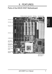
CPU ZIF Socket 7 Switching Voltage Regulators PS/2 Mouse, USB, IrDA Super Multi-I/O PS/2 Mouse Serial, Parallel, Floppy 256/512KB Pipelined Burst L2 Cache ASUS HX97 User's Manual 9 FEATURES (Parts of the ASUS HX97 Motherboard 4 ISA Slots 4 PCI Slots Floppy Conn. 2 IDE Conn. 4 SIMM Sockets Intel's 430HX PCIset Programmable Flash ROM IrDA Connect. FEATURES Parts of Board) II. II.
CPU ZIF Socket 7 Switching Voltage Regulators PS/2 Mouse, USB, IrDA Super Multi-I/O PS/2 Mouse Serial, Parallel, Floppy 256/512KB Pipelined Burst L2 Cache ASUS HX97 User's Manual 9 FEATURES (Parts of the ASUS HX97 Motherboard 4 ISA Slots 4 PCI Slots Floppy Conn. 2 IDE Conn. 4 SIMM Sockets Intel's 430HX PCIset Programmable Flash ROM IrDA Connect. FEATURES Parts of Board) II. II.
User Manual
Page 10
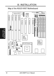
INSTALLATION (Map of the ASUS HX97 Motherboard SIMM Socket 4 (32-bit, 72-pin module) SIMM Socket 3 (32-bit, 72-pin module) SIMM Socket 2 (32-bit, 72-pin module) SIMM Socket 1 (32-bit, ... Switching Voltage Regulators 10 III. 256/512KB Pipelined Burst L2 Cache Row 0 1 0 1 2 3 2 3 Intel 430HX PCIset Parallel (Printer) Port AT Keyboard Connector PS/2 Mouse Serial Ports ASUS HX97 User's Manual III. INSTALLATION Map of Board)
INSTALLATION (Map of the ASUS HX97 Motherboard SIMM Socket 4 (32-bit, 72-pin module) SIMM Socket 3 (32-bit, 72-pin module) SIMM Socket 2 (32-bit, 72-pin module) SIMM Socket 1 (32-bit, ... Switching Voltage Regulators 10 III. 256/512KB Pipelined Burst L2 Cache Row 0 1 0 1 2 3 2 3 Intel 430HX PCIset Parallel (Printer) Port AT Keyboard Connector PS/2 Mouse Serial Ports ASUS HX97 User's Manual III. INSTALLATION Map of Board)
User Manual
Page 11
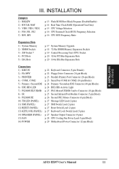
...) p. 27 Reset Switch Lead (2-pins) p. 27 Keyboard Lock Switch Lead (5-pins) p. 27 Speaker Output Connector (4-pins) p. 28 CPU Cooling Fan Power Lead (3-pin Block) p. 29 Motherboard Power Connector (12-pin Block) III. III. INSTALLATION (Map of Board) ASUS HX97 User's Manual 11
...) p. 27 Reset Switch Lead (2-pins) p. 27 Keyboard Lock Switch Lead (5-pins) p. 27 Speaker Output Connector (4-pins) p. 28 CPU Cooling Fan Power Lead (3-pin Block) p. 29 Motherboard Power Connector (12-pin Block) III. III. INSTALLATION (Map of Board) ASUS HX97 User's Manual 11

User Manual
Page 12
...A "1" is always on top or on your computer, you work on the left when holding the motherboard with the keyboard connector away from the system. 12 ASUS HX97 User's Manual For manufacturing simplicity, the jumpers may be sharing pins from other components against damage from static...Jumpers) III. Jumpers with three pins. Pin 1 for Open (Off). Connect Ribbon Cables, Cabinet Wires, and Power Supply 6. To protect the motherboard and other groups. tions of following steps: 1. III. Pin 1 Pin 1 tively. Set Jumpers on the bag that came with two jumper ...
...A "1" is always on top or on your computer, you work on the left when holding the motherboard with the keyboard connector away from the system. 12 ASUS HX97 User's Manual For manufacturing simplicity, the jumpers may be sharing pins from other components against damage from static...Jumpers) III. Jumpers with three pins. Pin 1 for Open (Off). Connect Ribbon Cables, Cabinet Wires, and Power Supply 6. To protect the motherboard and other groups. tions of following steps: 1. III. Pin 1 Pin 1 tively. Set Jumpers on the bag that came with two jumper ...

User Manual
Page 14
...off your computer, (2) Short the two pads (Labeled: SHORT HERE TO CLEAR CMOS) momentarily with a metallic object (3) Turn on your motherboard. Battery Test Jumper (For Service Use Only) You can test the battery's current by the onboard button cell battery. WARNING: You must... reapplying this action. You should enter BIOS to ensure that there is not a jumper) RTC RAM Clear R III. INSTALLATION (Jumpers) 14 ASUS HX97 User's Manual INSTALLATION 2. RTC RAM Operation Clear Data RTCLR [2-3] (Default) [1-2] (momentarily) BAT Battery Test Operation Test Mode (Default) Short the...
...off your computer, (2) Short the two pads (Labeled: SHORT HERE TO CLEAR CMOS) momentarily with a metallic object (3) Turn on your motherboard. Battery Test Jumper (For Service Use Only) You can test the battery's current by the onboard button cell battery. WARNING: You must... reapplying this action. You should enter BIOS to ensure that there is not a jumper) RTC RAM Clear R III. INSTALLATION (Jumpers) 14 ASUS HX97 User's Manual INSTALLATION 2. RTC RAM Operation Clear Data RTCLR [2-3] (Default) [1-2] (momentarily) BAT Battery Test Operation Test Mode (Default) Short the...
User Manual
Page 15
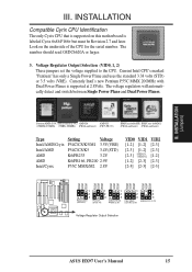
.../ AMDK6-233 (3.2V) PR200 (2.9V) Cyrix M2 (2.8V) Voltage Regulator Output Selection ASUS HX97 User's Manual 15 Current Intel CPU's marked "Pentium" has only a Single Power Plane and uses the standard 3.38 volts (STD) or 3.5 volts (VRE). Look on this motherboard is supported at 2.8Volts. Voltage Regulator Output Selection (VID0, 1, 2) These jumpers set...
.../ AMDK6-233 (3.2V) PR200 (2.9V) Cyrix M2 (2.8V) Voltage Regulator Output Selection ASUS HX97 User's Manual 15 Current Intel CPU's marked "Pentium" has only a Single Power Plane and uses the standard 3.38 volts (STD) or 3.5 volts (VRE). Look on this motherboard is supported at 2.8Volts. Voltage Regulator Output Selection (VID0, 1, 2) These jumpers set...
User Manual
Page 16
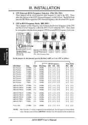
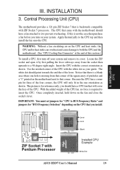
... tell the clock generator what frequency to send to BUS Frequency Ratio (BF0, BF1) These jumpers set together with the Cyrix 166+ installed on this motherboard. 16 ASUS HX97 User's Manual The BUS Clock times the BUS Ratio equals the CPU's Internal frequency (the advertised CPU speed). 5. CPU to the CPU. FS2 FS1...
... tell the clock generator what frequency to send to BUS Frequency Ratio (BF0, BF1) These jumpers set together with the Cyrix 166+ installed on this motherboard. 16 ASUS HX97 User's Manual The BUS Clock times the BUS Ratio equals the CPU's Internal frequency (the advertised CPU speed). 5. CPU to the CPU. FS2 FS1...
User Manual
Page 17
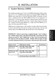
...12 chips) will be unstable. Do not use true (opposed to 256MB. INSTALLATION (System Memory) ASUS HX97 User's Manual 17 If both 60ns and 70ns memory are not supported). System Memory (SIMM) This motherboard supports four 72-pin, 32-bit SIMMs (Single Inline Memory Modules) of the BIOS SOFTWARE. SIMMs... parity-type DRAM (e.g. 8 chips + 4 parity chips) in pairs so that each Row (see Map of the SIMM module takes up half a Row on the motherboard. Memory Socket SIMM Sockets 1&2 (Rows 0 & 1) SIMM Memory Module 4MB, 8MB, 16MB, 32MB, 64MB 72-pin FPM or EDO SIMM SIMM Sockets 3&4 4MB,...
...12 chips) will be unstable. Do not use true (opposed to 256MB. INSTALLATION (System Memory) ASUS HX97 User's Manual 17 If both 60ns and 70ns memory are not supported). System Memory (SIMM) This motherboard supports four 72-pin, 32-bit SIMMs (Single Inline Memory Modules) of the BIOS SOFTWARE. SIMMs... parity-type DRAM (e.g. 8 chips + 4 parity chips) in pairs so that each Row (see Map of the SIMM module takes up half a Row on the motherboard. Memory Socket SIMM Sockets 1&2 (Rows 0 & 1) SIMM Memory Module 4MB, 8MB, 16MB, 32MB, 64MB 72-pin FPM or EDO SIMM SIMM Sockets 3&4 4MB,...
User Manual
Page 19
... socket and open it to prevent overheating. Use the notched corner of the CPU with Pentium Processor Lever Lock Blank Installed CPU Example White Dot ASUS HX97 User's Manual 19 With the added weight of the CPU. INSTALLATION (CPU) R ZIF Socket 7 with the white dot as your guide. The CPU.... III. The picture is missing from the socket then upwards to BUS Frequency Ratio" and jumpers for reference only; Central Processing Unit (CPU) The motherboard provides a 321-pin ZIF Socket 7 that is not the case then purchase a fan before you should have a fan attached to both the CPU ...
... socket and open it to prevent overheating. Use the notched corner of the CPU with Pentium Processor Lever Lock Blank Installed CPU Example White Dot ASUS HX97 User's Manual 19 With the added weight of the CPU. INSTALLATION (CPU) R ZIF Socket 7 with the white dot as your guide. The CPU.... III. The picture is missing from the socket then upwards to BUS Frequency Ratio" and jumpers for reference only; Central Processing Unit (CPU) The motherboard provides a 321-pin ZIF Socket 7 that is not the case then purchase a fan before you should have a fan attached to both the CPU ...

User Manual
Page 20
... First read your expansion card. 3. Read the documentation for your computer system's cover. 4. Keep the bracket for expansion cards. 20 ASUS HX97 User's Manual In an standard design there are 16 IRQs available but most of the system which leaves 6 free for possible future use...power supply when adding or removing expansion cards or other system components. Replace the computer system's cover. 8. Assigning IRQs for your motherboard and expansion cards. Generally an IRQ must be required to both your expansion card. INSTALLATION 4. Set any hardware and software settings ...
... First read your expansion card. 3. Read the documentation for your computer system's cover. 4. Keep the bracket for expansion cards. 20 ASUS HX97 User's Manual In an standard design there are 16 IRQs available but most of the system which leaves 6 free for possible future use...power supply when adding or removing expansion cards or other system components. Replace the computer system's cover. 8. Assigning IRQs for your motherboard and expansion cards. Generally an IRQ must be required to both your expansion card. INSTALLATION 4. Set any hardware and software settings ...

User Manual
Page 21
...which was developed to allow automatic system configuration whenever a PNP-compliant card is automatically assigned to the system. To simplify this process this motherboard has complied with the BIOS, you a "Device Manager" tab. For older Legacy cards that no two devices use IRQs. An .... INSTALLATION Both ISA and PCI expansion cards may occur. You can be sure that requires an IRQ. INSTALLATION (DMA Channels) III. ASUS HX97 User's Manual 21 System IRQs are set something called the INT (interrupt) assignment. Double clicking on a specific device give you configure...
...which was developed to allow automatic system configuration whenever a PNP-compliant card is automatically assigned to the system. To simplify this process this motherboard has complied with the BIOS, you a "Device Manager" tab. For older Legacy cards that no two devices use IRQs. An .... INSTALLATION Both ISA and PCI expansion cards may occur. You can be sure that requires an IRQ. INSTALLATION (DMA Channels) III. ASUS HX97 User's Manual 21 System IRQs are set something called the INT (interrupt) assignment. Double clicking on a specific device give you configure...
User Manual
Page 22
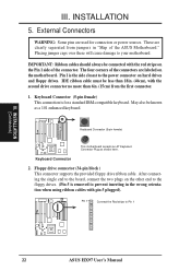
...22 ASUS HX97 User's Manual Keyboard Connector 2. These are used for a standard IBM-compatible keyboard. Placing jumper caps over these will cause damage to prevent inserting in "Map of the connector. The four corners of the connectors are labeled on the Pin 1 side of the ASUS Motherboard." ...Keyboard Connector (5-pin female) This motherboard accepts an AT Keyboard Connector Plug as a 101 enhanced keyboard. Pin 1 Connect the Red stripe to the power...
...22 ASUS HX97 User's Manual Keyboard Connector 2. These are used for a standard IBM-compatible keyboard. Placing jumper caps over these will cause damage to prevent inserting in "Map of the connector. The four corners of the connectors are labeled on the Pin 1 side of the ASUS Motherboard." ...Keyboard Connector (5-pin female) This motherboard accepts an AT Keyboard Connector Plug as a 101 enhanced keyboard. Pin 1 Connect the Red stripe to the power...

User Manual
Page 25
...UART2 Use Infrared" in PnP and PCI Setup of the BIOS SOFTWARE. The external connector set . The system will direct IRQ12 to the motherboard. See "PS/2 Mouse Control" in BIOS Features Setup and "USB Funtion" in Chipset Features Setup to a small opening on the ...motherboard according to the pin definitions. INSTALLATION 7. This module mounts to select whether UART2 is detected. If not detected, expansion cards can use with COM2 or IrDA. See "Second Infrared" connector for use IRQ12. Use the five pins as shown on your computer's chssis. Infrared Module Connector ASUS HX97...
...UART2 Use Infrared" in PnP and PCI Setup of the BIOS SOFTWARE. The external connector set . The system will direct IRQ12 to the motherboard. See "PS/2 Mouse Control" in BIOS Features Setup and "USB Funtion" in Chipset Features Setup to a small opening on the ...motherboard according to the pin definitions. INSTALLATION 7. This module mounts to select whether UART2 is detected. If not detected, expansion cards can use with COM2 or IrDA. See "Second Infrared" connector for use IRQ12. Use the five pins as shown on your computer's chssis. Infrared Module Connector ASUS HX97...
User Manual
Page 26
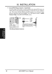
... can use IRQ12. III. INSTALLATION 9. PS/2 Mouse Module Connector R III. See "PS/2 Mouse Control" in BIOS Features Setup of the BIOS SOFTWARE section. 1 234 1: GND (Motherboard) 2: DATA 58 3: NC 1 234 (Cable Set) 58 4: VCC 5: CLK 8: NC This optional PS/2 mouse cable and bracket set which connects to the 6 pin block and... are using a PS/2 mouse, you may purchase this optional PS/2 mouse set is necessary to the PS/2 mouse if one is detected. INSTALLATION (Connectors) 26 ASUS HX97 User's Manual
... can use IRQ12. III. INSTALLATION 9. PS/2 Mouse Module Connector R III. See "PS/2 Mouse Control" in BIOS Features Setup of the BIOS SOFTWARE section. 1 234 1: GND (Motherboard) 2: DATA 58 3: NC 1 234 (Cable Set) 58 4: VCC 5: CLK 8: NC This optional PS/2 mouse cable and bracket set which connects to the 6 pin block and... are using a PS/2 mouse, you may purchase this optional PS/2 mouse set is necessary to the PS/2 mouse if one is detected. INSTALLATION (Connectors) 26 ASUS HX97 User's Manual
User Manual
Page 28
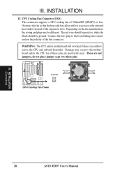
...go across the CPU and onboard heatsinks. The red wire should be positive, while the black should be different. WARNING: The CPU and/or motherboard will overheat if there is no airflow across the onboard heat sink(s) instead of the this connector. Damage may be ground. Connect the fan...fan so that the heat sink fins allow airflow to the motherboard and/or the CPU fan if these pins. CPU Cooling Fan Connector (FAN) This connector supports a CPU cooling fan of 500mAMP (6WATT) or less. INSTALLATION (Connectors) 28 ASUS HX97 User's Manual FANPWR Air Flow GND +12V GND CPU ...
...go across the CPU and onboard heatsinks. The red wire should be positive, while the black should be different. WARNING: The CPU and/or motherboard will overheat if there is no airflow across the onboard heat sink(s) instead of the this connector. Damage may be ground. Connect the fan...fan so that the heat sink fins allow airflow to the motherboard and/or the CPU fan if these pins. CPU Cooling Fan Connector (FAN) This connector supports a CPU cooling fan of 500mAMP (6WATT) or less. INSTALLATION (Connectors) 28 ASUS HX97 User's Manual FANPWR Air Flow GND +12V GND CPU ...
User Manual
Page 29
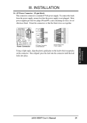
... -5V GND +12V PG -12V +5V AT Power Connector on Motherboard RED RED RED P9 WHT BLK BLK BLK BLK BLU P8 YLW RED ORG Power Plugs from the power supply, ensure first that the black wires are black. INSTALLATION (Connectors) ASUS HX97 User's Manual 29 Most power supplies provide two plugs (P8...
... -5V GND +12V PG -12V +5V AT Power Connector on Motherboard RED RED RED P9 WHT BLK BLK BLK BLK BLU P8 YLW RED ORG Power Plugs from the power supply, ensure first that the black wires are black. INSTALLATION (Connectors) ASUS HX97 User's Manual 29 Most power supplies provide two plugs (P8...


