
CUWE-RM User Manual
Page 4
... Checklist 7 2. CONTENTS 1. BIOS SETUP 45 4.1 Managing and Updating Your BIOS 45 4.1.1 Upon First Use of the Computer System 45 4.1.2 Updating BIOS Procedures 46 4.2 BIOS Setup Program 49 4.2.1 BIOS Menu Bar 50 4.2.2 Legend Bar 50 4.3 Main Menu 52 4.3.1 Primary & Secondary Master/Slave 53 4.4 Advanced Menu 58 4.4.1 Chip Configuration 62 4.4.2 I/O Device Configuration 65 4.4.3 PCI Configuration 67 4.4.4 Shadow Configuration 70 4 ASUS CUWE-RM User's Manual FEATURES 8 2.1 The ASUS CUWE-RM Motherboard 8 2.1.1 Specifications 8 2.1.2 Optional Components 9 2.1.3 Performance 10...
... Checklist 7 2. CONTENTS 1. BIOS SETUP 45 4.1 Managing and Updating Your BIOS 45 4.1.1 Upon First Use of the Computer System 45 4.1.2 Updating BIOS Procedures 46 4.2 BIOS Setup Program 49 4.2.1 BIOS Menu Bar 50 4.2.2 Legend Bar 50 4.3 Main Menu 52 4.3.1 Primary & Secondary Master/Slave 53 4.4 Advanced Menu 58 4.4.1 Chip Configuration 62 4.4.2 I/O Device Configuration 65 4.4.3 PCI Configuration 67 4.4.4 Shadow Configuration 70 4 ASUS CUWE-RM User's Manual FEATURES 8 2.1 The ASUS CUWE-RM Motherboard 8 2.1.1 Specifications 8 2.1.2 Optional Components 9 2.1.3 Performance 10...

CUWE-RM User Manual
Page 8
... motion video acceleration. Each PCI slot can gain about 12% performance over that of frequency and Vcore voltage all through BIOS setup when JumperFree™ mode is carefully designed for 2D graphics. • ASUS Graphics Driver! Allows processor settings and easy overclocking of the standard graphics driver (2D high-end graphics WinMark) using ASUS' custom graphics driver. Supports processors with EPP and ECP capabilities. • Integrated IDE! Supports Wake-On-LAN, Wake-On-Ring, Keyboard Wake-Up, and BIOS Wake-Up. • AMR Slot! Controller supports...
... motion video acceleration. Each PCI slot can gain about 12% performance over that of frequency and Vcore voltage all through BIOS setup when JumperFree™ mode is carefully designed for 2D graphics. • ASUS Graphics Driver! Allows processor settings and easy overclocking of the standard graphics driver (2D high-end graphics WinMark) using ASUS' custom graphics driver. Supports processors with EPP and ECP capabilities. • Integrated IDE! Supports Wake-On-LAN, Wake-On-Ring, Keyboard Wake-Up, and BIOS Wake-Up. • AMR Slot! Controller supports...
CUWE-RM User Manual
Page 9
...; Firmware Hub! ASUS CUWE-RM User's Manual 9 Provides Vcore and CPU/ SDRAM frequency adjustments, boot block write protection, and HD/SCSI/MO/ ZIP/CD/Floppy boot selection. Includes complete online help to guide you through a new design, battery drain is removed and through the audio software. • Space Savings! Supports chassis intrusion monitoring through the ASUS ASIC. Integrated Consumer IR and Standard IR supports an optional remote control package for virtually automatic setup. • Smart BIOS! 4Mbit firmware...
...; Firmware Hub! ASUS CUWE-RM User's Manual 9 Provides Vcore and CPU/ SDRAM frequency adjustments, boot block write protection, and HD/SCSI/MO/ ZIP/CD/Floppy boot selection. Includes complete online help to guide you through a new design, battery drain is removed and through the audio software. • Space Savings! Supports chassis intrusion monitoring through the ASUS ASIC. Integrated Consumer IR and Standard IR supports an optional remote control package for virtually automatic setup. • Smart BIOS! 4Mbit firmware...
CUWE-RM User Manual
Page 10
.../ 33 (IDE DMA Mode 2), PIO Modes 3 & 4, and supports Enhanced IDE devices, such as required by PC'99. • HighestAudio Quality! ASUS smart series motherboards support the new generation memory, Synchronous Dynamic Random Access Memory (SDRAM), which increases the data transfer rate to noise ratio) of ACPI, an ACPI-supported OS, such as an alternative to upgrade current IDE devices or cables. • Concurrent PCI! With these new technology is compatible with two connectors that you...
.../ 33 (IDE DMA Mode 2), PIO Modes 3 & 4, and supports Enhanced IDE devices, such as required by PC'99. • HighestAudio Quality! ASUS smart series motherboards support the new generation memory, Synchronous Dynamic Random Access Memory (SDRAM), which increases the data transfer rate to noise ratio) of ACPI, an ACPI-supported OS, such as an alternative to upgrade current IDE devices or cables. • Concurrent PCI! With these new technology is compatible with two connectors that you...
CUWE-RM User Manual
Page 11
... the BIOS, the power button can determine the stage the computer is necessary to present enormous user interfaces and run large applications. This allows a computer to critical motherboard components. Chassis LEDs now act as the Soft-Off (see ATX Power Switch Lead in . Today's operating systems such as the "Standby" (a.k.a. With this motherboard supports processor thermal sensing and auto-protection. • Voltage Monitoring and Alert! ASUS CUWE-RM User's Manual 11...
... the BIOS, the power button can determine the stage the computer is necessary to present enormous user interfaces and run large applications. This allows a computer to critical motherboard components. Chassis LEDs now act as the Soft-Off (see ATX Power Switch Lead in . Today's operating systems such as the "Standby" (a.k.a. With this motherboard supports processor thermal sensing and auto-protection. • Voltage Monitoring and Alert! ASUS CUWE-RM User's Manual 11...
CUWE-RM User Manual
Page 12
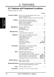
...-I/O Chipset 13 Main Memory Maximum 512MB support 3 DIMM Sockets 5 PC100 SDRAM support Expansion Slots 3 PCI Slots 16 1 Audio Modem Riser (AMR) Slot 20 System I/O 2 IDE Connectors (UltraDMA33/66 Support 6 1 Floppy Disk Driver Connector 8 1 Serial COM1 Connector 24 1 Parallel Port Connector 23 2 USB Connectors 25 1 PS/2 Mouse Connector Top) 26 1 PS/2 Keyboard Connector Bottom) 26 1 Serial Header 1 3D Graphics Graphics Memory Controller Hub (GMCH) 1 VGA Monitor Output Connector 22 TV/Digital LCD Headers 15 4MB onboard high-speed SDRAM 12 Audio Yamaha PCI Audio (optional...
...-I/O Chipset 13 Main Memory Maximum 512MB support 3 DIMM Sockets 5 PC100 SDRAM support Expansion Slots 3 PCI Slots 16 1 Audio Modem Riser (AMR) Slot 20 System I/O 2 IDE Connectors (UltraDMA33/66 Support 6 1 Floppy Disk Driver Connector 8 1 Serial COM1 Connector 24 1 Parallel Port Connector 23 2 USB Connectors 25 1 PS/2 Mouse Connector Top) 26 1 PS/2 Keyboard Connector Bottom) 26 1 Serial Header 1 3D Graphics Graphics Memory Controller Hub (GMCH) 1 VGA Monitor Output Connector 22 TV/Digital LCD Headers 15 4MB onboard high-speed SDRAM 12 Audio Yamaha PCI Audio (optional...

CUWE-RM User Manual
Page 14
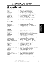
... IDELED 14 ASUS CUWE-RM User's Manual 3. H/W SETUP Motherboard Layout 3. HARDWARE SETUP 3.1 Motherboard Layout PS/2 T: Mouse B: Keyboard VIO USB T: Port1 B: Port2 COM1 CPU_FAN DIMM Socket 1 (64/72-bit, 168-pin module) DIMM Socket 2 (64/72-bit, 168-pin module) DIMM Socket 3 (64/72-bit, 168-pin module) Secondary IDE Primary IDE FLOPPY ATX Power Connector PARALLEL PORT GAME_AUDIO DIP Switches DSW Socket 370 PWR_FAN CHA_FAN VGA Line Out COM2 LCDTV0 IR_CON Line In Mic In MIC2 VIDEO AUX Super I/O CD LCDTV1 TAD Audio Modem...
... IDELED 14 ASUS CUWE-RM User's Manual 3. H/W SETUP Motherboard Layout 3. HARDWARE SETUP 3.1 Motherboard Layout PS/2 T: Mouse B: Keyboard VIO USB T: Port1 B: Port2 COM1 CPU_FAN DIMM Socket 1 (64/72-bit, 168-pin module) DIMM Socket 2 (64/72-bit, 168-pin module) DIMM Socket 3 (64/72-bit, 168-pin module) Secondary IDE Primary IDE FLOPPY ATX Power Connector PARALLEL PORT GAME_AUDIO DIP Switches DSW Socket 370 PWR_FAN CHA_FAN VGA Line Out COM2 LCDTV0 IR_CON Line In Mic In MIC2 VIDEO AUX Super I/O CD LCDTV1 TAD Audio Modem...
CUWE-RM User Manual
Page 15
... p.36 IDE Activity LED Lead (2 pins) 14) CHA_, CPU_, PWR_FAN p.36 Chassis, CPU, Power Supply Fan Connectors (Three 3-pin) 15) IR_CON p.37 Infrared Module Connectors (10-1 pins) 16) COM2 p.37 Serial Port COM2 Header (10-1 pins) 17) SMB p.38 SMBus Connector (5-1 pins) 18) LCDTV0/LCDTV1 p.38 LCD-TV Headers (Two 14 pins) (optional) 19) TAD, AUX, VIDEO, CD p.39 Internal Audio Connectors (Four 4-pins) 20) MIC2 p.39 Internal Microphone Connector (3 pins) 21) SPD0/SPD1 p.40 Digital Audio Interface Headers (Two 2-pins) ASUS CUWE-RM User's Manual 15
... p.36 IDE Activity LED Lead (2 pins) 14) CHA_, CPU_, PWR_FAN p.36 Chassis, CPU, Power Supply Fan Connectors (Three 3-pin) 15) IR_CON p.37 Infrared Module Connectors (10-1 pins) 16) COM2 p.37 Serial Port COM2 Header (10-1 pins) 17) SMB p.38 SMBus Connector (5-1 pins) 18) LCDTV0/LCDTV1 p.38 LCD-TV Headers (Two 14 pins) (optional) 19) TAD, AUX, VIDEO, CD p.39 Internal Audio Connectors (Four 4-pins) 20) MIC2 p.39 Internal Microphone Connector (3 pins) 21) SPD0/SPD1 p.40 Digital Audio Interface Headers (Two 2-pins) ASUS CUWE-RM User's Manual 15

CUWE-RM User Manual
Page 19
... be disabled. H/W SETUP Motherboard Settings SPK AUD_EN1 SPK AUD_EN1 ADN# AUD_EN2 CUWE-RM ® CUWE-RM Audio Codec Setting 3 2 1 Enable ADN# AUD_EN2 3 2 1 Disable ASUS CUWE-RM User's Manual 19 If using all of these jumpers. Disable the onboard audio codec if you are using a PCI audio card on any of the expansion slots or a primary AMR on audio model only The onboard 32-bit PCI audio may be enabled or disabled using a PCI audio expansion card, Onboard AC'97 Audio Controller in 4.4.2 I /O Device Configuration must also be disabled. 3. Disable the onboard audio if...
... be disabled. H/W SETUP Motherboard Settings SPK AUD_EN1 SPK AUD_EN1 ADN# AUD_EN2 CUWE-RM ® CUWE-RM Audio Codec Setting 3 2 1 Enable ADN# AUD_EN2 3 2 1 Disable ASUS CUWE-RM User's Manual 19 If using all of these jumpers. Disable the onboard audio codec if you are using a PCI audio card on any of the expansion slots or a primary AMR on audio model only The onboard 32-bit PCI audio may be enabled or disabled using a PCI audio expansion card, Onboard AC'97 Audio Controller in 4.4.2 I /O Device Configuration must also be disabled. 3. Disable the onboard audio if...

CUWE-RM User Manual
Page 20
... to enter BIOS setup to correct the problem. If this case, there is possible through motherboard settings or BIOS setup. HARDWARE SETUP 5) PCI 3 Volt Setting (PCI3VSEL) This jumper allows you have locked frequency multiples. Setting PCI3VSEL Enable 3VSB [1-2] (default) Disable 3VSB [2-3] 3. Setting Normal Safe Mode SAFE_MD [1-2] (default) [2-3] CUWE-RM ® CUWE-RM Safe Mode Setting SAFE_MD 3 2 1 Normal (Default) 3 2 1 Safe Mode 20 ASUS CUWE-RM User's Manual In this occurs, enable Safe Mode to Enable 3 VSB. 3. If you to select the voltage supplied to...
... to enter BIOS setup to correct the problem. If this case, there is possible through motherboard settings or BIOS setup. HARDWARE SETUP 5) PCI 3 Volt Setting (PCI3VSEL) This jumper allows you have locked frequency multiples. Setting PCI3VSEL Enable 3VSB [1-2] (default) Disable 3VSB [2-3] 3. Setting Normal Safe Mode SAFE_MD [1-2] (default) [2-3] CUWE-RM ® CUWE-RM Safe Mode Setting SAFE_MD 3 2 1 Normal (Default) 3 2 1 Safe Mode 20 ASUS CUWE-RM User's Manual In this occurs, enable Safe Mode to Enable 3 VSB. 3. If you to select the voltage supplied to...

CUWE-RM User Manual
Page 42
...'s power supply. 29) ATX Power Switch Lead (2-pin PWR) The system power is not in the inbox. The LED will remain lit when there is no signal and blink when there is in Windows 98, reinstall Windows 98 using the command line setup /p j. To enable ACPI support in sleep mode. 26) Keyboard Lock Switch Lead (2-pin KEYLOCK) This 2-pin connector connects to the case-mounted key switch to allow keyboard locking. 27) System Warning Speaker Connector (4-pin SPEAKER) This 4-pin connector connects to the case...
...'s power supply. 29) ATX Power Switch Lead (2-pin PWR) The system power is not in the inbox. The LED will remain lit when there is no signal and blink when there is in Windows 98, reinstall Windows 98 using the command line setup /p j. To enable ACPI support in sleep mode. 26) Keyboard Lock Switch Lead (2-pin KEYLOCK) This 2-pin connector connects to the case-mounted key switch to allow keyboard locking. 27) System Warning Speaker Connector (4-pin SPEAKER) This 4-pin connector connects to the case...

CUWE-RM User Manual
Page 43
... jumper settings and connections or call your system user's manual. 4. 3. The LED on tests. You may have failed a power-on your devices in an endless loop One long beep followed by three short beeps High frequency beeps when system is working Meaning No error during POST No DRAM installed or detected Video card not found or video card memory bad CPU overheated System running , the BIOS will alarm beeps or additional messages will light when the ATX power switch is equipped with ). 3. Award BIOS Beep Codes Beep...
... jumper settings and connections or call your system user's manual. 4. 3. The LED on tests. You may have failed a power-on your devices in an endless loop One long beep followed by three short beeps High frequency beeps when system is working Meaning No error during POST No DRAM installed or detected Video card not found or video card memory bad CPU overheated System running , the BIOS will alarm beeps or additional messages will light when the ATX power switch is equipped with ). 3. Award BIOS Beep Codes Beep...

CUWE-RM User Manual
Page 45
... work with DOS prompt in Windows and will not work with a Flash Memory Writer utility (AFLASH.EXE) to a bootable floppy disk in DOS mode. Type COPY D:\AFLASH\AFLASH.EXE A:\ (assuming D is your hard drive. NOTE: BIOS setup must specify "Floppy" as the first item in DOS mode. Type FORMAT A:/S at the DOS prompt to the just created boot disk. ASUS CUWE-RM User's Manual 45 Larger numbers represent a newer BIOS file. 1. BIOS SETUP 4.1 Managing and Updating Your BIOS 4.1.1 Upon First Use...
... work with DOS prompt in Windows and will not work with a Flash Memory Writer utility (AFLASH.EXE) to a bootable floppy disk in DOS mode. Type COPY D:\AFLASH\AFLASH.EXE A:\ (assuming D is your hard drive. NOTE: BIOS setup must specify "Floppy" as the first item in DOS mode. Type FORMAT A:/S at the DOS prompt to the just created boot disk. ASUS CUWE-RM User's Manual 45 Larger numbers represent a newer BIOS file. 1. BIOS SETUP 4.1 Managing and Updating Your BIOS 4.1.1 Upon First Use...
CUWE-RM User Manual
Page 59
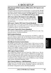
... This function controls the ECC capability in cache. Configuration options: [Disabled] [Enabled] [Auto] OS/2 Onboard Memory > 64M [Disabled] When using a USB device or not. CPU Vcore (when CPU Speed is set it manually, always refer to detect a USB device on startup a PS/2 mouse is set this on startup. If detected, the USB controller will be enabled. BIOS SETUP Advanced Menu ASUS CUWE-RM User's Manual 59 4. The bus frequency (external frequency) multiplied by the bus multiple equals the CPU's internal frequency (the CPU speed). The configuration options vary depending...
... This function controls the ECC capability in cache. Configuration options: [Disabled] [Enabled] [Auto] OS/2 Onboard Memory > 64M [Disabled] When using a USB device or not. CPU Vcore (when CPU Speed is set it manually, always refer to detect a USB device on startup a PS/2 mouse is set this on startup. If detected, the USB controller will be enabled. BIOS SETUP Advanced Menu ASUS CUWE-RM User's Manual 59 4. The bus frequency (external frequency) multiplied by the bus multiple equals the CPU's internal frequency (the CPU speed). The configuration options vary depending...
CUWE-RM User Manual
Page 65
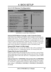
... Modem Controller, Audio Controller [Auto] [Auto] allows the motherboard's BIOS to reverse the hardware drive letter assignments of your floppy disk drives. BIOS SETUP I /O Device Configuration 4. if no modem/audio device is detected, the onboard modem/audio controller will be enabled; Serial Port 1 and Serial Port 2 must have conflicts with the onboard modem/audio controller, you may set the addresses for the onboard serial connectors. Configuration options: [3F8H/IRQ4] [2F8H/IRQ3] [3E8H/IRQ4] [2E8H/IRQ10] [Disabled] ASUS CUWE-RM User's Manual 65 If a modem/audio device is...
... Modem Controller, Audio Controller [Auto] [Auto] allows the motherboard's BIOS to reverse the hardware drive letter assignments of your floppy disk drives. BIOS SETUP I /O Device Configuration 4. if no modem/audio device is detected, the onboard modem/audio controller will be enabled; Serial Port 1 and Serial Port 2 must have conflicts with the onboard modem/audio controller, you may set the addresses for the onboard serial connectors. Configuration options: [3F8H/IRQ4] [2F8H/IRQ3] [3E8H/IRQ4] [2E8H/IRQ10] [Disabled] ASUS CUWE-RM User's Manual 65 If a modem/audio device is...

CUWE-RM User Manual
Page 67
... BIOS SETUP 4.4.3 PCI Configuration 4. Configuration options: [Auto] [Disabled] ASUS CUWE-RM User's Manual 67 Configuration options: [Auto] [NA] [3] [4] [5] [7] [9] [10] [11] [12] [14] [15] PCI/VGA Palette Snoop [Disabled] Some nonstandard VGA cards, such as graphics accelerators or MPEG video cards, may not show colors properly. The setting [Enabled] should correct this on Symbios SCSI card can be enabled; If the Symbios SCSI card is detected, the onboard Symbios SCSI BIOS will be disabled. [Disabled] will disable the motherboard's Symbios SCSI BIOS so that the BIOS...
... BIOS SETUP 4.4.3 PCI Configuration 4. Configuration options: [Auto] [Disabled] ASUS CUWE-RM User's Manual 67 Configuration options: [Auto] [NA] [3] [4] [5] [7] [9] [10] [11] [12] [14] [15] PCI/VGA Palette Snoop [Disabled] Some nonstandard VGA cards, such as graphics accelerators or MPEG video cards, may not show colors properly. The setting [Enabled] should correct this on Symbios SCSI card can be enabled; If the Symbios SCSI card is detected, the onboard Symbios SCSI BIOS will be disabled. [Disabled] will disable the motherboard's Symbios SCSI BIOS so that the BIOS...
CUWE-RM User Manual
Page 68
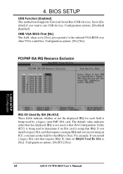
... ISA card is being used by a legacy (non-PnP) ISA card. Configuration options: [Disabled] [Enabled] ONB VGA BIOS First [No] This field, when set IRQ10 Used By ISA to the onboard VGA BIOS over other VGA controllers. BIOS SETUP PCI Configuration IRQ XX Used By ISA [No/ICU] These fields indicate whether or not the displayed IRQ for that requires IRQ 10, then set to [Yes], gives priority to [Yes]. Configuration options: [No/ICU] [Yes] 68 ASUS CUWE-RM User's Manual...
... ISA card is being used by a legacy (non-PnP) ISA card. Configuration options: [Disabled] [Enabled] ONB VGA BIOS First [No] This field, when set IRQ10 Used By ISA to the onboard VGA BIOS over other VGA controllers. BIOS SETUP PCI Configuration IRQ XX Used By ISA [No/ICU] These fields indicate whether or not the displayed IRQ for that requires IRQ 10, then set to [Yes], gives priority to [Yes]. Configuration options: [No/ICU] [Yes] 68 ASUS CUWE-RM User's Manual...

CUWE-RM User Manual
Page 118
... at the bottom-right corner of the window. 7. APPENDIX Modem Riser 7. APPENDIX 7.2.4 Software Setup in Windows 98 The Modem Riser supports the Plug and Play feature. It allows your CD-ROM drive. After the driver is located, click Next and then click Finish. 6. Select your CD-ROM drive is completed. 2. Follow the procedure below to Settings, click Control Panel, double click Modems, click the General...
... at the bottom-right corner of the window. 7. APPENDIX Modem Riser 7. APPENDIX 7.2.4 Software Setup in Windows 98 The Modem Riser supports the Plug and Play feature. It allows your CD-ROM drive. After the driver is located, click Next and then click Finish. 6. Select your CD-ROM drive is completed. 2. Follow the procedure below to Settings, click Control Panel, double click Modems, click the General...
CUWE-RM User Manual
Page 126
... 114 Hardware Setup 17 CPU Installation 26 Memory Installation 25 HDD Power Down 72 Head 55 Headers Digital Audio Interface 40 Digital LCD 38 Serial Port COM 2 37 High Priority PCI Mode 64 I I/O Voltage Setting 18 IDE Activity LED Lead 36 IDE Connectors 34 IDE Hard Drive 76 INF Update Utility for 810 Chipset 84 Installation CPU 26 Expansion Card 27 Memory 25 Installed Memory 57 Intel Security Driver 87 Internal Audio Connectors 39 Internal Microphone Connector 39 Interrupts Request Table 29 Standard Assignments 28 IRQ XX Used By...
... 114 Hardware Setup 17 CPU Installation 26 Memory Installation 25 HDD Power Down 72 Head 55 Headers Digital Audio Interface 40 Digital LCD 38 Serial Port COM 2 37 High Priority PCI Mode 64 I I/O Voltage Setting 18 IDE Activity LED Lead 36 IDE Connectors 34 IDE Hard Drive 76 INF Update Utility for 810 Chipset 84 Installation CPU 26 Expansion Card 27 Memory 25 Installed Memory 57 Intel Security Driver 87 Internal Audio Connectors 39 Internal Microphone Connector 39 Interrupts Request Table 29 Standard Assignments 28 IRQ XX Used By...
CUWE-RM User Manual
Page 127
... Onboard Parallel Port 66 Onboard PCI IDE Enable 64 Onboard Serial Port 1 65 Onboard Serial Port 2 65 Onboard VGA 63 Operating Systems 81 OS/2 Onboard Memory > 64M 59 Other Boot Device Select 76 P Parallel Port Connector 32 Parallel Port Mode 66 PC Probe Setup 93 Using 105 PC-cillin 98 Setup 96 PCI 3 Volt Setting 20 PCI Latency Timer 67 PCI/VGA Palette Snoop 67 PIO Mode 55 Plug & Play O/S 77 Power Fan Speed 75 Power Management 71 Procedure CPU Installation 26 Hardware Setup 17 Procedures Modem Riser Installation 117 Updating BIOS...
... Onboard Parallel Port 66 Onboard PCI IDE Enable 64 Onboard Serial Port 1 65 Onboard Serial Port 2 65 Onboard VGA 63 Operating Systems 81 OS/2 Onboard Memory > 64M 59 Other Boot Device Select 76 P Parallel Port Connector 32 Parallel Port Mode 66 PC Probe Setup 93 Using 105 PC-cillin 98 Setup 96 PCI 3 Volt Setting 20 PCI Latency Timer 67 PCI/VGA Palette Snoop 67 PIO Mode 55 Plug & Play O/S 77 Power Fan Speed 75 Power Management 71 Procedure CPU Installation 26 Hardware Setup 17 Procedures Modem Riser Installation 117 Updating BIOS...


