C8HM70-I User's Manual
Page 8
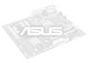
... or the user manual for Memory QVL (Qualify Vendor List) Integrated Graphics Processor- C8HM70-I SERIES specifications summary CPU Chipset Memory Graphics Expansion slots Storage LAN Audio USB ASUS unique features Back Panel I/O ports Internal I /HDMI only) 1 x LAN (RJ-45) port 4 x USB 2.0/1.1 ports 2 ... audio connector(s) (AAFP) 1 x Internal speaker connector(s) (continued on the next page) viii ASUS MyLogo 2 - Ai Suite II 1 x PS/2 keyboard/mouse combo port 1 x VGA port 1 x HDMI port (C8HM70-I /O connectors Intel® Celeron® 847 (BGA1023) Intel® HM70 chipset 2 x SODIMM...
... or the user manual for Memory QVL (Qualify Vendor List) Integrated Graphics Processor- C8HM70-I SERIES specifications summary CPU Chipset Memory Graphics Expansion slots Storage LAN Audio USB ASUS unique features Back Panel I/O ports Internal I /HDMI only) 1 x LAN (RJ-45) port 4 x USB 2.0/1.1 ports 2 ... audio connector(s) (AAFP) 1 x Internal speaker connector(s) (continued on the next page) viii ASUS MyLogo 2 - Ai Suite II 1 x PS/2 keyboard/mouse combo port 1 x VGA port 1 x HDMI port (C8HM70-I /O connectors Intel® Celeron® 847 (BGA1023) Intel® HM70 chipset 2 x SODIMM...
C8HM70-I User's Manual
Page 10
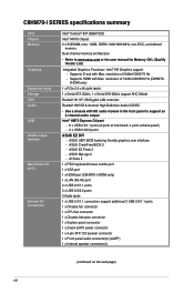
... module) VGA Super I/O LAN_USB34 RTL 8111F AUDIO AAFP ALC 887 Intel® HM70 64Mb BIOS SATA6G_1 SATA3G_1 EATXPWR Lithium Cell CMOS Power USB1112 CLRTC F_PANEL C8HM70-I/HDMI SPEAKER CHASSIS PCIEX16_1 SB_PWR ASUS C8HM70-I/HDMI motherboard User Manual 1 x Serial ATA 3.0 Gb/s cable 1 x Serial ATA 6.0 Gb/s cable 1 x I/O-Shield User Guide Support DVD •...
... module) VGA Super I/O LAN_USB34 RTL 8111F AUDIO AAFP ALC 887 Intel® HM70 64Mb BIOS SATA6G_1 SATA3G_1 EATXPWR Lithium Cell CMOS Power USB1112 CLRTC F_PANEL C8HM70-I/HDMI SPEAKER CHASSIS PCIEX16_1 SB_PWR ASUS C8HM70-I/HDMI motherboard User Manual 1 x Serial ATA 3.0 Gb/s cable 1 x Serial ATA 6.0 Gb/s cable 1 x I/O-Shield User Guide Support DVD •...
C8HM70-I User's Manual
Page 11
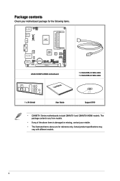
... location of the following precautions before you install motherboard components or change any motherboard settings. • Unplug the power cord from the power supply. SB_PWR C8HM70-I/HDMI ON OFF Standby Power Powered Off C8HM70-I/HDMI Onboard LED ASUS C8HM70-I Series 1-1 Product introduction 1 1.1 Before you proceed Take note of the onboard LED.
... location of the following precautions before you install motherboard components or change any motherboard settings. • Unplug the power cord from the power supply. SB_PWR C8HM70-I/HDMI ON OFF Standby Power Powered Off C8HM70-I/HDMI Onboard LED ASUS C8HM70-I Series 1-1 Product introduction 1 1.1 Before you proceed Take note of the onboard LED.
C8HM70-I User's Manual
Page 13
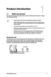
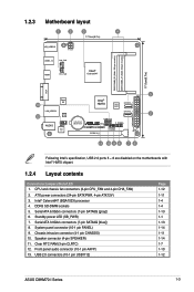
... LED (SB_PWR) 7. USB 2.0 connectors (10-1 pin USB1112) Page 1-12 1-11 1-4 1-4 1-13 1-1 1-13 1-14 1-11 1-14 1-7 1-10 1-12 ASUS C8HM70-I /HDMI PCIEX16_1 F_PANEL SPEAKER CHASSIS SB_PWR 11 10 9 8 7 6 Following Intel's specification, USB 2.0 ports 5 ~ 8 are disabled on the motherboards with Intel® HM70...ATX power connectors (24-pin EATXPWR, 4-pin ATX12V) 3. 1.2.3 Motherboard layout 1 2 3 4 17.0cm(6.7in) KB_USB910 ATX12V USB3_12 CHA_FAN HDMI CPU_FAN Intel® Celeron847 DDR3 DIMM_B1 (64bit, 204-pin module) DDR3 DIMM_A1 (64bit, 204-pin module) 17.0cm(6.7in) VGA 5 Super...
... LED (SB_PWR) 7. USB 2.0 connectors (10-1 pin USB1112) Page 1-12 1-11 1-4 1-4 1-13 1-1 1-13 1-14 1-11 1-14 1-7 1-10 1-12 ASUS C8HM70-I /HDMI PCIEX16_1 F_PANEL SPEAKER CHASSIS SB_PWR 11 10 9 8 7 6 Following Intel's specification, USB 2.0 ports 5 ~ 8 are disabled on the motherboards with Intel® HM70...ATX power connectors (24-pin EATXPWR, 4-pin ATX12V) 3. 1.2.3 Motherboard layout 1 2 3 4 17.0cm(6.7in) KB_USB910 ATX12V USB3_12 CHA_FAN HDMI CPU_FAN Intel® Celeron847 DDR3 DIMM_B1 (64bit, 204-pin module) DDR3 DIMM_A1 (64bit, 204-pin module) 17.0cm(6.7in) VGA 5 Super...

C8HM70-I User's Manual
Page 17
...You do not help, remove the onboard battery and move the cap back to clear the CMOS RTC RAM data. CLRTC 12 23 C8HM70-I/HDMI Normal (Default) Clear RTC C8HM70-I Series 1-7 Removing the cap will cause system boot failure! • If the steps above do not need to clear the RTC... the power cord. 2. Plug the power cord and turn ON the computer. 4. Move the jumper cap from pins 1-2 (default) to default values. ASUS C8HM70-I /HDMI Clear RTC RAM To erase the RTC RAM: 1. Shut down the key during the boot process and enter BIOS setup to overclocking. The onboard button...
...You do not help, remove the onboard battery and move the cap back to clear the CMOS RTC RAM data. CLRTC 12 23 C8HM70-I/HDMI Normal (Default) Clear RTC C8HM70-I Series 1-7 Removing the cap will cause system boot failure! • If the steps above do not need to clear the RTC... the power cord. 2. Plug the power cord and turn ON the computer. 4. Move the jumper cap from pins 1-2 (default) to default values. ASUS C8HM70-I /HDMI Clear RTC RAM To erase the RTC RAM: 1. Shut down the key during the boot process and enter BIOS setup to overclocking. The onboard button...
C8HM70-I User's Manual
Page 19
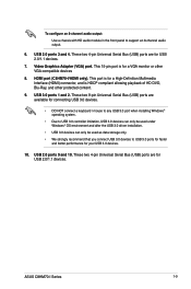
... for a VGA monitor or other protected content. 9. Video Graphics Adapter (VGA) port. USB 3.0 ports 1 and 2. USB 2.0 ports 3 and 4. HDMI port (C8HM70-I Series 1-9 These two 4-pin Universal Serial Bus (USB) ports are for USB 2.0/1.1 devices. ASUS C8HM70-I /HDMI only). This 15-pin port is HDCP compliant allowing playback of HD DVD, Blu-Ray, and other VGA...
... for a VGA monitor or other protected content. 9. Video Graphics Adapter (VGA) port. USB 3.0 ports 1 and 2. USB 2.0 ports 3 and 4. HDMI port (C8HM70-I Series 1-9 These two 4-pin Universal Serial Bus (USB) ports are for USB 2.0/1.1 devices. ASUS C8HM70-I /HDMI only). This 15-pin port is HDCP compliant allowing playback of HD DVD, Blu-Ray, and other VGA...
C8HM70-I User's Manual
Page 21
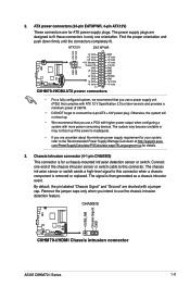
... or switch sends a high-level signal to this connector when a chassis component is then generated as a chassis intrusion event. CHASSIS +5VSB_MB Chassis Signal GND C8HM70-I/HDMI C8HM70-I/HDMI Chassis intrusion connector ASUS C8HM70-I /HDMI ATX power connectors • For a fully configured system, we recommend that you use a power supply unit (PSU) that you use the chassis intrusion...
... or switch sends a high-level signal to this connector when a chassis component is then generated as a chassis intrusion event. CHASSIS +5VSB_MB Chassis Signal GND C8HM70-I/HDMI C8HM70-I/HDMI Chassis intrusion connector ASUS C8HM70-I /HDMI ATX power connectors • For a fully configured system, we recommend that you use a power supply unit (PSU) that you use the chassis intrusion...

C8HM70-I User's Manual
Page 23
See section 2.5.3 SATA Configuration for details. 7. GND RSATA_TXP1 RSATA_TXN1 GND RSATA_RXN1 RSATA_RXP1 GND ASUS C8HM70-I /HDMI SATA 3.0Gb/s connector • You must install Windows® XP Service Pack 3 or later version before...See section 2.5.3 SATA Configuration for details. Serial ATA 6.0Gb/s connectors (7-pin SATA6G [gray]) This connector connects to [AHCI]. SATA3G_1 C8HM70-I/HDMI C8HM70-I Series 1-13 SATA6G_1 C8HM70-I/HDMI C8HM70-I/HDMI SATA 6.0Gb/s connector • You must install Windows® XP Service Pack 3 or later version before using Serial ATA hard ...
See section 2.5.3 SATA Configuration for details. 7. GND RSATA_TXP1 RSATA_TXN1 GND RSATA_RXN1 RSATA_RXP1 GND ASUS C8HM70-I /HDMI SATA 3.0Gb/s connector • You must install Windows® XP Service Pack 3 or later version before...See section 2.5.3 SATA Configuration for details. Serial ATA 6.0Gb/s connectors (7-pin SATA6G [gray]) This connector connects to [AHCI]. SATA3G_1 C8HM70-I/HDMI C8HM70-I Series 1-13 SATA6G_1 C8HM70-I/HDMI C8HM70-I/HDMI SATA 6.0Gb/s connector • You must install Windows® XP Service Pack 3 or later version before using Serial ATA hard ...
C8HM70-I User's Manual
Page 29
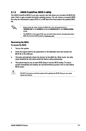
... using this utility, rename the BIOS file in the support DVD may not be the latest version. ASUS C8HM70-I /HDMI model. • The BIOS file in the removable device to C8HM70I.CAP for the C8HM70-I model and HM70IH.CAP for the BIOS file. When found, the utility reads the BIOS file and... enters ASUS EZ Flash 2 utility automatically. 4. Recovering the BIOS To recover the BIOS: 1. You can cause system boot ...
... using this utility, rename the BIOS file in the support DVD may not be the latest version. ASUS C8HM70-I /HDMI model. • The BIOS file in the removable device to C8HM70I.CAP for the C8HM70-I model and HM70IH.CAP for the BIOS file. When found, the utility reads the BIOS file and... enters ASUS EZ Flash 2 utility automatically. 4. Recovering the BIOS To recover the BIOS: 1. You can cause system boot ...
C8HM70-I User's Manual
Page 31
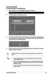
... SATA hard disk drives after updating BIOS. • Ensure to load the BIOS default settings to ensure system compatibility and stability. Select Yes and press . ASUS C8HM70-I .CAP 8390656 2012-02-09 17:30:48 Note [Enter] Select or Load [Up/Down/Home/End] Move [Tab] Switch [B] Backup [V] Drive Info [Esc] Exit... utility automatically exits to the DOS prompt after updating the BIOS file if you to section 2.9 Exit menu for DOS V1.30 Current ROM BOARD: C8HM70-I/HDMI VER: 0202 DATE: 08/29/2012 Update ROM BOARD: Unknown VER: Unknown DATE: Unknown PATH...
... SATA hard disk drives after updating BIOS. • Ensure to load the BIOS default settings to ensure system compatibility and stability. Select Yes and press . ASUS C8HM70-I .CAP 8390656 2012-02-09 17:30:48 Note [Enter] Select or Load [Up/Down/Home/End] Move [Tab] Switch [B] Backup [V] Drive Info [Esc] Exit... utility automatically exits to the DOS prompt after updating the BIOS file if you to section 2.9 Exit menu for DOS V1.30 Current ROM BOARD: C8HM70-I/HDMI VER: 0202 DATE: 08/29/2012 Update ROM BOARD: Unknown VER: Unknown DATE: Unknown PATH...


