C8HM70-I User's Manual
Page 5
... your local power company. • If the power supply is set to fix it , carefully read all the manuals that all cables are correctly connected and the power cables are not damaged. If you detect any area where it may become wet. • Place the product on it by yourself. ...Safety information Electrical safety • To prevent electrical shock hazard, disconnect the power cable from the electrical outlet before relocating the system. • When adding or removing devices to or from the system, ensure that the power...
... your local power company. • If the power supply is set to fix it , carefully read all the manuals that all cables are correctly connected and the power cables are not damaged. If you detect any area where it may become wet. • Place the product on it by yourself. ...Safety information Electrical safety • To prevent electrical shock hazard, disconnect the power cable from the electrical outlet before relocating the system. • When adding or removing devices to or from the system, ensure that the power...
C8HM70-I User's Manual
Page 10
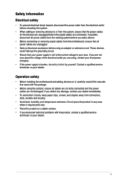
... module) VGA Super I/O LAN_USB34 RTL 8111F AUDIO AAFP ALC 887 Intel® HM70 64Mb BIOS SATA6G_1 SATA3G_1 EATXPWR Lithium Cell CMOS Power USB1112 CLRTC F_PANEL C8HM70-I/HDMI SPEAKER CHASSIS PCIEX16_1 SB_PWR ASUS C8HM70-I/HDMI motherboard User Manual 1 x Serial ATA 3.0 Gb/s cable 1 x Serial ATA 6.0 Gb/s cable 1 x I/O-Shield User Guide Support DVD • C8HM70-I Series motherboards include C8HM70-I and C8HM70-I/HDMI models.
... module) VGA Super I/O LAN_USB34 RTL 8111F AUDIO AAFP ALC 887 Intel® HM70 64Mb BIOS SATA6G_1 SATA3G_1 EATXPWR Lithium Cell CMOS Power USB1112 CLRTC F_PANEL C8HM70-I/HDMI SPEAKER CHASSIS PCIEX16_1 SB_PWR ASUS C8HM70-I/HDMI motherboard User Manual 1 x Serial ATA 3.0 Gb/s cable 1 x Serial ATA 6.0 Gb/s cable 1 x I/O-Shield User Guide Support DVD • C8HM70-I Series motherboards include C8HM70-I and C8HM70-I/HDMI models.
C8HM70-I User's Manual
Page 11
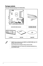
...to static electricity. • Hold components by the edges to indicate that you should shut down the system and unplug the power cable before touching any component. • Before handling components, use a grounded wrist strap or touch a safely grounded object or a ...it on a grounded antistatic pad or in any motherboard component. This is switched off mode. SB_PWR C8HM70-I/HDMI ON OFF Standby Power Powered Off C8HM70-I/HDMI Onboard LED ASUS C8HM70-I Series 1-1 The illustration below shows the location of the following precautions before you install motherboard components or...
...to static electricity. • Hold components by the edges to indicate that you should shut down the system and unplug the power cable before touching any component. • Before handling components, use a grounded wrist strap or touch a safely grounded object or a ...it on a grounded antistatic pad or in any motherboard component. This is switched off mode. SB_PWR C8HM70-I/HDMI ON OFF Standby Power Powered Off C8HM70-I/HDMI Onboard LED ASUS C8HM70-I Series 1-1 The illustration below shows the location of the following precautions before you install motherboard components or...

C8HM70-I User's Manual
Page 20
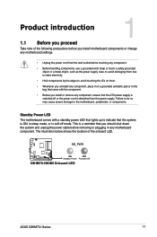
... SENSE2_RETUR AGND NC NC NC AAFP PIN 1 PIN 1 MIC2 MICPWR Line out_R NC Line out_L PORT1 L PORT1 R PORT2 R SENSE_SEND PORT2 L C8HM70-I/HDMI HD-audio-compliant Legacy AC'97 pin definition compliant definition C8HM70-I/HDMI Front panel audio connector • We recommend that supports either HD Audio or legacy AC`97 audio standard. By default... audio connector (10-1 pin AAFP) This connector is set the item to [HD]. See section 2.5.6 Onboard Devices Configuration for a chassis-mounted front panel audio I /O module cable to this connector, set to [AC97].
... SENSE2_RETUR AGND NC NC NC AAFP PIN 1 PIN 1 MIC2 MICPWR Line out_R NC Line out_L PORT1 L PORT1 R PORT2 R SENSE_SEND PORT2 L C8HM70-I/HDMI HD-audio-compliant Legacy AC'97 pin definition compliant definition C8HM70-I/HDMI Front panel audio connector • We recommend that supports either HD Audio or legacy AC`97 audio standard. By default... audio connector (10-1 pin AAFP) This connector is set the item to [HD]. See section 2.5.6 Onboard Devices Configuration for a chassis-mounted front panel audio I /O module cable to this connector, set to [AC97].
C8HM70-I User's Manual
Page 21
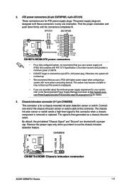
...push down firmly until the connectors completely fit. CHASSIS +5VSB_MB Chassis Signal GND C8HM70-I/HDMI C8HM70-I/HDMI Chassis intrusion connector ASUS C8HM70-I /HDMI ATX power connectors • For a fully configured system, we recommend that ...cable to use a power supply unit (PSU) that you use the chassis intrusion detection feature. 2. Chassis intrusion connector (4-1 pin CHASSIS) This connector is inadequate. • If you intend to this connector when a chassis component is then generated as a chassis intrusion event. ATX12V EATXPWR +12V DC +12V DC C8HM70-I/HDMI...
...push down firmly until the connectors completely fit. CHASSIS +5VSB_MB Chassis Signal GND C8HM70-I/HDMI C8HM70-I/HDMI Chassis intrusion connector ASUS C8HM70-I /HDMI ATX power connectors • For a fully configured system, we recommend that ...cable to use a power supply unit (PSU) that you use the chassis intrusion detection feature. 2. Chassis intrusion connector (4-1 pin CHASSIS) This connector is inadequate. • If you intend to this connector when a chassis component is then generated as a chassis intrusion event. ATX12V EATXPWR +12V DC +12V DC C8HM70-I/HDMI...
C8HM70-I User's Manual
Page 22
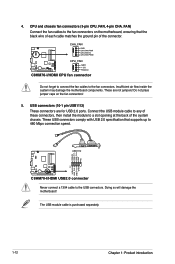
... FAN PWM C8HM70-I/HDMI CPU_FAN GND +12V Rotation C8HM70-I /HDMI USB2.0 connector Never connect a 1394 cable to the fan connectors. USB+5V USB_P11USB_P11+ GND NC PIN 1 USB+5V USB_P12USB_P12+ GND USB1112 C8HM70-I/HDMI C8HM70-I /HDMI CPU fan connector Do not forget to connect the fan cables to the ...USB connectors. These USB connectors comply with USB 2.0 specification that the black wire of each cable matches the ground pin of these connectors...
... FAN PWM C8HM70-I/HDMI CPU_FAN GND +12V Rotation C8HM70-I /HDMI USB2.0 connector Never connect a 1394 cable to the fan connectors. USB+5V USB_P11USB_P11+ GND NC PIN 1 USB+5V USB_P12USB_P12+ GND USB1112 C8HM70-I/HDMI C8HM70-I /HDMI CPU fan connector Do not forget to connect the fan cables to the ...USB connectors. These USB connectors comply with USB 2.0 specification that the black wire of each cable matches the ground pin of these connectors...

C8HM70-I User's Manual
Page 23
See section 2.5.3 SATA Configuration for details. GND RSATA_TXP1 RSATA_TXN1 GND RSATA_RXN1 RSATA_RXP1 GND ASUS C8HM70-I /HDMI SATA 6.0Gb/s connector • You must install Windows® XP Service Pack 3 or later version before using Serial ATA hard ...Serial ATA 3.0Gb/s connectors (7-pin SATA3G [blue]) This connector connects to Serial ATA 6.0 Gb/s hard disk drives via Serial ATA 3.0 Gb/s signal cables. SATA3G_1 C8HM70-I/HDMI C8HM70-I/HDMI SATA 3.0Gb/s connector • You must install Windows® XP Service Pack 3 or later version before using Serial ATA hard disk drives. •...
See section 2.5.3 SATA Configuration for details. GND RSATA_TXP1 RSATA_TXN1 GND RSATA_RXN1 RSATA_RXP1 GND ASUS C8HM70-I /HDMI SATA 6.0Gb/s connector • You must install Windows® XP Service Pack 3 or later version before using Serial ATA hard ...Serial ATA 3.0Gb/s connectors (7-pin SATA3G [blue]) This connector connects to Serial ATA 6.0 Gb/s hard disk drives via Serial ATA 3.0 Gb/s signal cables. SATA3G_1 C8HM70-I/HDMI C8HM70-I/HDMI SATA 3.0Gb/s connector • You must install Windows® XP Service Pack 3 or later version before using Serial ATA hard disk drives. •...
C8HM70-I User's Manual
Page 24
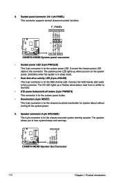
SPEAKER +5V GND GND Speaker Out CC88HM H7M0-I/7H0DM-II PIN 1 C8HM70-I /HDMI System panel connector • System power LED (2-pin PWRLED) This 2-pin connector is for the HDD Activity LED. The system power LED lights up ...button. • Reset button (2-pin RESET) This 2-pin connector is for the system power LED. 8. Ground HWRST# (NC) C8HM70-I/HDMI +HD_LED RESET C8HM70-I /HDMI Speaker Out Connector 1-14 Chapter 1: Product introduction Connect the HDD Activity LED cable to this connector. The speaker allows you turn on the system power, and blinks when the system is...
SPEAKER +5V GND GND Speaker Out CC88HM H7M0-I/7H0DM-II PIN 1 C8HM70-I /HDMI System panel connector • System power LED (2-pin PWRLED) This 2-pin connector is for the HDD Activity LED. The system power LED lights up ...button. • Reset button (2-pin RESET) This 2-pin connector is for the system power LED. 8. Ground HWRST# (NC) C8HM70-I/HDMI +HD_LED RESET C8HM70-I /HDMI Speaker Out Connector 1-14 Chapter 1: Product introduction Connect the HDD Activity LED cable to this connector. The speaker allows you turn on the system power, and blinks when the system is...
C8HM70-I User's Manual
Page 57
The use of shielded cables for connection of the FCC Rules. Operation is required to assure compliance with Part 15 of the monitor to the graphics card is subject to ... to an outlet on a circuit different from that interference will not occur in a particular installation. This equipment has been tested and found to this equipment. C8HM70-I Series A-1 Appendices Notices Federal Communications Commission Statement This device complies with FCC regulations. Changes or modifications to comply with manufacturer's instructions, may cause undesired operation...
The use of shielded cables for connection of the FCC Rules. Operation is required to assure compliance with Part 15 of the monitor to the graphics card is subject to ... to an outlet on a circuit different from that interference will not occur in a particular installation. This equipment has been tested and found to this equipment. C8HM70-I Series A-1 Appendices Notices Federal Communications Commission Statement This device complies with FCC regulations. Changes or modifications to comply with manufacturer's instructions, may cause undesired operation...


