
User Manual
Page 1
AT4NM10-I Motherboard
AT4NM10-I Motherboard
User Manual
Page 3
Contents Notices...v Safety information vi About this guide vi AT4NM10-I specifications summary viii Chapter 1: Product introduction 1.1 Before you proceed 1-1 1.2 Motherboard overview 1-2 1.2.1 Motherboard layout 1-2 1.2.2 Layout contents 1-2 1.3 Central Processing Unit (CPU 1-3 1.4 System memory 1-3 1.4.1 Overview 1-3 1.4.2 Memory configurations 1-4 1.5 Expansion slot 1-8 ...DVD information 1-18 Chapter 2: BIOS information 2.1 Managing and updating your BIOS 2-1 2.1.1 ASUS Update utility 2-1 2.1.2 ASUS EZ Flash 2 2-2 2.1.3 ASUS CrashFree BIOS 2-3 2.2 BIOS setup program 2-4 iii
Contents Notices...v Safety information vi About this guide vi AT4NM10-I specifications summary viii Chapter 1: Product introduction 1.1 Before you proceed 1-1 1.2 Motherboard overview 1-2 1.2.1 Motherboard layout 1-2 1.2.2 Layout contents 1-2 1.3 Central Processing Unit (CPU 1-3 1.4 System memory 1-3 1.4.1 Overview 1-3 1.4.2 Memory configurations 1-4 1.5 Expansion slot 1-8 ...DVD information 1-18 Chapter 2: BIOS information 2.1 Managing and updating your BIOS 2-1 2.1.1 ASUS Update utility 2-1 2.1.2 ASUS EZ Flash 2 2-2 2.1.3 ASUS CrashFree BIOS 2-3 2.2 BIOS setup program 2-4 iii

User Manual
Page 5
... radio noise emissions from that to comply with the limits for connection of electronic products. If this equipment. DO NOT throw the motherboard in a particular installation. This symbol of the FCC Rules. Notices Federal Communications Commission Statement This device complies with Part 15 of ...crossed out wheeled bin indicates that the product (electrical and electronic equipment) should not be placed in our products at ASUS REACH website at http://green.asus.com/english/REACH.htm. DO NOT throw the mercury-containing button cell battery in a residential installation. This symbol ...
... radio noise emissions from that to comply with the limits for connection of electronic products. If this equipment. DO NOT throw the motherboard in a particular installation. This symbol of the FCC Rules. Notices Federal Communications Commission Statement This device complies with Part 15 of ...crossed out wheeled bin indicates that the product (electrical and electronic equipment) should not be placed in our products at ASUS REACH website at http://green.asus.com/english/REACH.htm. DO NOT throw the mercury-containing button cell battery in a residential installation. This symbol ...

User Manual
Page 6
...an adapter or extension cord. If you are not sure about the voltage of the electrical outlet you need when installing and configuring the motherboard. vi Contact a qualified service technician or your dealer immediately. • To avoid short circuits, keep paper clips, screws, and staples... power cables are not damaged. How this guide This user guide contains the information you are also provided. Detailed descriptions of the motherboard and the new technology it supports. • Chapter 2: BIOS information This chapter tells how to change system settings through the BIOS...
...an adapter or extension cord. If you are not sure about the voltage of the electrical outlet you need when installing and configuring the motherboard. vi Contact a qualified service technician or your dealer immediately. • To avoid short circuits, keep paper clips, screws, and staples... power cables are not damaged. How this guide This user guide contains the information you are also provided. Detailed descriptions of the motherboard and the new technology it supports. • Chapter 2: BIOS information This chapter tells how to change system settings through the BIOS...
User Manual
Page 10
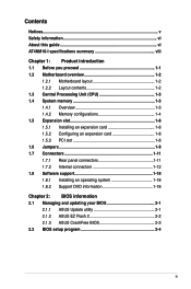
... power cord is a reminder that you for the list of the following precautions before touching any motherboard settings. • Unplug the power cord from the power supply. Refer to page ix for buying an ASUS® AT4NM10-I Onboard LED 1-1 Chapter 1: Product introduction If any component, place it , check the items in your retailer...
... power cord is a reminder that you for the list of the following precautions before touching any motherboard settings. • Unplug the power cord from the power supply. Refer to page ix for buying an ASUS® AT4NM10-I Onboard LED 1-1 Chapter 1: Product introduction If any component, place it , check the items in your retailer...
User Manual
Page 11
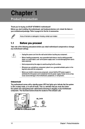
...of the chassis. Place this side towards the rear of the chassis. Onboard LED 1-1 5. Doing so can damage the motherboard. 1.2.2 Layout contents Connectors/Jumpers/Slots/LED Page Connectors/Jumpers/Slots/LED Page Keyboard/mouse power and USB device 1. Serial ...pin PS2_USBPW1-4, 3-pin USBPW5- 1-10 9. 8) Chassis intrusion connector (4-1 pin CHASSIS) 1-14 2. Front panel audio connector (10-1 pin AAFP) 1-15 ASUS AT4NM10-I Place four screws into the chassis in the correct orientation. Clear RTC RAM (3-pin CLRTC) 1-9 4. The edge with external ports goes to the ...
...of the chassis. Place this side towards the rear of the chassis. Onboard LED 1-1 5. Doing so can damage the motherboard. 1.2.2 Layout contents Connectors/Jumpers/Slots/LED Page Connectors/Jumpers/Slots/LED Page Keyboard/mouse power and USB device 1. Serial ...pin PS2_USBPW1-4, 3-pin USBPW5- 1-10 9. 8) Chassis intrusion connector (4-1 pin CHASSIS) 1-14 2. Front panel audio connector (10-1 pin AAFP) 1-15 ASUS AT4NM10-I Place four screws into the chassis in the correct orientation. Clear RTC RAM (3-pin CLRTC) 1-9 4. The edge with external ports goes to the ...
User Manual
Page 12
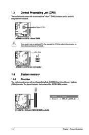
...: Channel Channel A Sockets DIMM_A1 and DIMM_A2 AT4NM10-I AT4NM10-I CPU - D410 AT4NM10-I 240-pin DDR2 DIMM sockets 1-3 Chapter 1: Product introduction Atom D410 If you need to use an additional CPU fan, connect the CPU fan cable to the connector on the motherboard labeled CPU_FAN. AT4NM10-I 1.3 Central Processing Unit (CPU) The motherboard comes with two Double Data Rate...
...: Channel Channel A Sockets DIMM_A1 and DIMM_A2 AT4NM10-I AT4NM10-I CPU - D410 AT4NM10-I 240-pin DDR2 DIMM sockets 1-3 Chapter 1: Product introduction Atom D410 If you need to use an additional CPU fan, connect the CPU fan cable to the connector on the motherboard labeled CPU_FAN. AT4NM10-I 1.3 Central Processing Unit (CPU) The motherboard comes with two Double Data Rate...
User Manual
Page 13
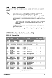
..., it is less than 4GB. • This motherboard does not support DIMMs made up of memory, we recommend that you are using a 32-bit Windows® OS. - AT4NM10-I 1-4 A-Data Corsair G.SKILL G.SKILL M2OAD5H3J4170I1C53 2048MB... - • - • - • - • - • - • - • - • - • - • - • - • (continued on the next page) ASUS AT4NM10-I Motherboard Qualified Vendors Lists (QVL) DDR2-667 MHz capability Vendor Part No. 1.4.2 Memory configurations You may install 512MB, 1GB, and 2GB unbuffered non‑ECC DDR2...
..., it is less than 4GB. • This motherboard does not support DIMMs made up of memory, we recommend that you are using a 32-bit Windows® OS. - AT4NM10-I 1-4 A-Data Corsair G.SKILL G.SKILL M2OAD5H3J4170I1C53 2048MB... - • - • - • - • - • - • - • - • - • - • - • - • (continued on the next page) ASUS AT4NM10-I Motherboard Qualified Vendors Lists (QVL) DDR2-667 MHz capability Vendor Part No. 1.4.2 Memory configurations You may install 512MB, 1GB, and 2GB unbuffered non‑ECC DDR2...
User Manual
Page 17
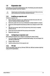
...and make the necessary hardware settings for later use . Remove the system unit cover (if your motherboard is completely seated on the slot. 5. Secure the card to use . 4. ASUS AT4NM10-I 1-8 Before installing the expansion card, read the documentation that you removed earlier. 6. Keep the ..., and other cards that it by adjusting the software settings. 1. 1.5 Expansion slot In the future, you physical injury and damage motherboard components. 1.5.1 Installing an expansion card To install an expansion card: 1. Unplug the power cord before adding or removing expansion cards....
...and make the necessary hardware settings for later use . Remove the system unit cover (if your motherboard is completely seated on the slot. 5. Secure the card to use . 4. ASUS AT4NM10-I 1-8 Before installing the expansion card, read the documentation that you removed earlier. 6. Keep the ..., and other cards that it by adjusting the software settings. 1. 1.5 Expansion slot In the future, you physical injury and damage motherboard components. 1.5.1 Installing an expansion card To install an expansion card: 1. Unplug the power cord before adding or removing expansion cards....
User Manual
Page 21
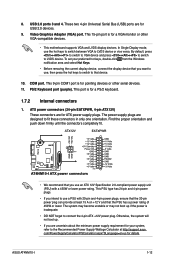
...power rating of 450W or lower. COM port. The power supply plugs are for ATX power supply plugs. 8. Video Graphics Adapter (VGA) port. ASUS AT4NM10-I ATX power connectors • We recommend that you want to use the hot keys to switch between VGA to LVDS device. Otherwise, the system ...PSU type has 24-pin and 4-pin power plugs. • If you are for pointing devices or other VGA-compatible devices. • This motherboard supports VGA and LVDS display devices. In Single Display mode, use , then press the hot keys to switch to the Recommended Power Supply Wattage...
...power rating of 450W or lower. COM port. The power supply plugs are for ATX power supply plugs. 8. Video Graphics Adapter (VGA) port. ASUS AT4NM10-I ATX power connectors • We recommend that you want to use the hot keys to switch between VGA to LVDS device. Otherwise, the system ...PSU type has 24-pin and 4-pin power plugs. • If you are for pointing devices or other VGA-compatible devices. • This motherboard supports VGA and LVDS display devices. In Single Display mode, use , then press the hot keys to switch to the Recommended Power Supply Wattage...
User Manual
Page 22
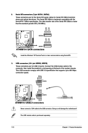
... the standard parallel ATA (133 MB/s). The USB module cable is backward compatible with USB 2.0 specification that supports up to the USB connector. AT4NM10-I 2. Doing so will damage the motherboard! AT4NM10-I SATA connectors Install the Windows® XP Service Pack 2 or later versions before using Serial ATA. 3. The Serial ATA 3Gb/s is purchased...
... the standard parallel ATA (133 MB/s). The USB module cable is backward compatible with USB 2.0 specification that supports up to the USB connector. AT4NM10-I 2. Doing so will damage the motherboard! AT4NM10-I SATA connectors Install the Windows® XP Service Pack 2 or later versions before using Serial ATA. 3. The Serial ATA 3Gb/s is purchased...
User Manual
Page 24
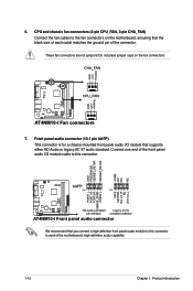
AT4NM10-I AT4NM10-I /O module cable to avail of the motherboard's high-definition audio capability. 1-15 Chapter 1: Product introduction 6. These fan connectors are not jumpers! Connect one end of the connector. CPU and chassis fan connectors (3-...) Connect the fan cables to the fan connectors on the fan connectors! Do not place jumper caps on the motherboard, ensuring that supports either HD Audio or legacy AC`97 audio standard. AT4NM10-I AT4NM10-I /O module that the black wire of each cable matches the ground pin of the front panel audio I Front panel...
AT4NM10-I AT4NM10-I /O module cable to avail of the motherboard's high-definition audio capability. 1-15 Chapter 1: Product introduction 6. These fan connectors are not jumpers! Connect one end of the connector. CPU and chassis fan connectors (3-...) Connect the fan cables to the fan connectors on the fan connectors! Do not place jumper caps on the motherboard, ensuring that supports either HD Audio or legacy AC`97 audio standard. AT4NM10-I AT4NM10-I /O module that the black wire of each cable matches the ground pin of the front panel audio I Front panel...
User Manual
Page 27
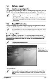
...DVD to avail all motherboard features. ASUS AT4NM10-I 1-18 Refer to your OS documentation for detailed information. • Ensure that you can install to locate the file ASSETUP.EXE from the BIN folder. Double-click the ASSETUP.EXE to change at www.asus.com for better compatibility ...DVD Place the Support DVD to display their respective menus. Click an icon to display Support DVD/ motherboard information Click an item to maximize the features of ASUS motherboard. Always install the latest OS version and corresponding updates to install If Autorun is enabled in your hardware...
...DVD to avail all motherboard features. ASUS AT4NM10-I 1-18 Refer to your OS documentation for detailed information. • Ensure that you can install to locate the file ASSETUP.EXE from the BIN folder. Double-click the ASSETUP.EXE to change at www.asus.com for better compatibility ...DVD Place the Support DVD to display their respective menus. Click an icon to display Support DVD/ motherboard information Click an item to maximize the features of ASUS motherboard. Always install the latest OS version and corresponding updates to install If Autorun is enabled in your hardware...

User Manual
Page 28
.... Updating the BIOS To update the BIOS: 1. Select the ASUS FTP site nearest you update the BIOS using the ASUS Update utility. 2.1.1 ASUS Update utility The ASUS Update is a utility that allows you to manage, save, and update the motherboard BIOS in Windows® environment. • ASUS Update requires an Internet connection either through a network or...
.... Updating the BIOS To update the BIOS: 1. Select the ASUS FTP site nearest you update the BIOS using the ASUS Update utility. 2.1.1 ASUS Update utility The ASUS Update is a utility that allows you to manage, save, and update the motherboard BIOS in Windows® environment. • ASUS Update requires an Internet connection either through a network or...

User Manual
Page 30
...down or reset the system while updating the BIOS to prevent system boot failure! 2.1.3 ASUS CrashFree BIOS The ASUS CrashFree BIOS is an auto recovery tool that contains the updated BIOS file. • Before using the motherboard support DVD or a removable device that allows you to restore the BIOS file when ... off the system after the utility completes the updating process and turn on the system. 2. Download the latest BIOS file from the ASUS website at www.asus.com. • The removable device that contains the BIOS file to the USB port or to the optical drive or the removable device...
...down or reset the system while updating the BIOS to prevent system boot failure! 2.1.3 ASUS CrashFree BIOS The ASUS CrashFree BIOS is an auto recovery tool that contains the updated BIOS file. • Before using the motherboard support DVD or a removable device that allows you to restore the BIOS file when ... off the system after the utility completes the updating process and turn on the system. 2. Download the latest BIOS file from the ASUS website at www.asus.com. • The removable device that contains the BIOS file to the USB port or to the optical drive or the removable device...

User Manual
Page 31
...the BIOS Setup program. Do this motherboard. 2.3 Main menu When you enter the BIOS Setup program, the Main menu screen appears, giving you an overview of the basic system information. Select the Load Setups Default item under the Exit Menu. ASUS AT4NM10-I 2-4 We recommend to always shut... down the system properly from a running operating system can cause damage to your screen. • Visit the ASUS website at startup: • Press during the Power-On Self Test...
...the BIOS Setup program. Do this motherboard. 2.3 Main menu When you enter the BIOS Setup program, the Main menu screen appears, giving you an overview of the basic system information. Select the Load Setups Default item under the Exit Menu. ASUS AT4NM10-I 2-4 We recommend to always shut... down the system properly from a running operating system can cause damage to your screen. • Visit the ASUS website at startup: • Press during the Power-On Self Test...
User Manual
Page 38
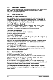
... turn on state, whatever the system state was before the AC power loss. Configuration options: [Disabled] [Enabled] 2.5.5 APM Configuration Restore on the keyboard to the motherboard, the field shows N/A. Configuration options: [Disabled] [Enabled] Power On By Ring [Disabled] Allows you to use specific keys on AC Power Loss [Power Off]... options: [Disabled] [Enabled] 2.5.6 Hardware Monitor CPU/MB Temperature [xxxºC/xxxºF] or [Ignored] The onboard hardware monitor automatically detects and displays the CPU/motherboard temperature. If the fan is set values.
... turn on state, whatever the system state was before the AC power loss. Configuration options: [Disabled] [Enabled] 2.5.5 APM Configuration Restore on the keyboard to the motherboard, the field shows N/A. Configuration options: [Disabled] [Enabled] Power On By Ring [Disabled] Allows you to use specific keys on AC Power Loss [Power Off]... options: [Disabled] [Enabled] 2.5.6 Hardware Monitor CPU/MB Temperature [xxxºC/xxxºF] or [Ignored] The onboard hardware monitor automatically detects and displays the CPU/motherboard temperature. If the fan is set values.

User Manual
Page 44
Country: TAIWAN Authorized representative in Europe: ASUS COMPUTER GmbH Address, City: HARKORT STR. 21-23, 40880 RATINGEN Country: GERMANY declare the following apparatus: Product name : Motherboard Model name : AT4NM10-I Conforms to begin affixing CE marking:2010 Signature Phone/... harmful interference, and (2) this device must accept any interference received, including interference that the product Product Name : Motherboard Model Number : AT4NM10-I conform with part 15 of Conformity We, the undersigned, Manufacturer: Address, City: ASUSTek COMPUTER INC. No. 150...
Country: TAIWAN Authorized representative in Europe: ASUS COMPUTER GmbH Address, City: HARKORT STR. 21-23, 40880 RATINGEN Country: GERMANY declare the following apparatus: Product name : Motherboard Model name : AT4NM10-I Conforms to begin affixing CE marking:2010 Signature Phone/... harmful interference, and (2) this device must accept any interference received, including interference that the product Product Name : Motherboard Model Number : AT4NM10-I conform with part 15 of Conformity We, the undersigned, Manufacturer: Address, City: ASUSTek COMPUTER INC. No. 150...


