
User Manual
Page 2
... infringe. SPECIFICATIONS AND INFORMATION CONTAINED IN THIS MANUAL ARE FURNISHED FOR INFORMATIONAL USE ONLY, AND ARE SUBJECT TO CHANGE AT ANY TIME WITHOUT NOTICE, AND SHOULD NOT BE CONSTRUED AS A COMMITMENT BY ASUS. Offer to have it from http://support.asus.com/download; The GPL and LGPL licensed code in receipt of this manual, including the products and software described in...
... infringe. SPECIFICATIONS AND INFORMATION CONTAINED IN THIS MANUAL ARE FURNISHED FOR INFORMATIONAL USE ONLY, AND ARE SUBJECT TO CHANGE AT ANY TIME WITHOUT NOTICE, AND SHOULD NOT BE CONSTRUED AS A COMMITMENT BY ASUS. Offer to have it from http://support.asus.com/download; The GPL and LGPL licensed code in receipt of this manual, including the products and software described in...
User Manual
Page 3
... Unit (CPU 1-3 1.4 System memory 1-3 1.4.1 Overview 1-3 1.4.2 Memory configurations 1-4 1.5 Expansion slot 1-8 1.5.1 Installing an expansion card 1-8 1.5.2 Configuring an expansion card 1-8 1.5.3 PCI slot 1-8 1.6 Jumpers 1-9 1.7 Connectors 1-11 1.7.1 Rear panel connectors 1-11 1.7.2 Internal connectors 1-12 1.8 Software support 1-18 1.8.1 Installing an operating system 1-18 1.8.2 Support DVD information 1-18 Chapter 2: BIOS information 2.1 Managing and updating your BIOS 2-1 2.1.1 ASUS Update utility 2-1 2.1.2 ASUS EZ Flash 2 2-2 2.1.3 ASUS CrashFree BIOS 2-3 2.2 BIOS setup...
... Unit (CPU 1-3 1.4 System memory 1-3 1.4.1 Overview 1-3 1.4.2 Memory configurations 1-4 1.5 Expansion slot 1-8 1.5.1 Installing an expansion card 1-8 1.5.2 Configuring an expansion card 1-8 1.5.3 PCI slot 1-8 1.6 Jumpers 1-9 1.7 Connectors 1-11 1.7.1 Rear panel connectors 1-11 1.7.2 Internal connectors 1-12 1.8 Software support 1-18 1.8.1 Installing an operating system 1-18 1.8.2 Support DVD information 1-18 Chapter 2: BIOS information 2.1 Managing and updating your BIOS 2-1 2.1.1 ASUS Update utility 2-1 2.1.2 ASUS EZ Flash 2 2-2 2.1.3 ASUS CrashFree BIOS 2-3 2.2 BIOS setup...
User Manual
Page 8
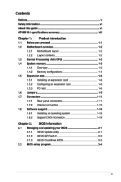
...x PCI slot 2 x Serial ATA 3Gb/s ports support AHCI mode IDT 92HD73C 6-channel High Definition Audio CODEC Realtek® RTL8112L PCIe Gigabit LAN controller Supports up to 8 USB 2.0/1.1 ports (4 ports at mid-board, 4 ports at back panel) ASUS CrashFree BIOS 3 ASUS EZ Flash 2 ASUS MyLogo 2™ ASUS AI NET 2 ASUS Express Gate 1 x PS/2 Keyboard port 1 x PS/2 Mouse port 1 x COM port 1 x VGA port 1 x LPT port 1 x LAN (RJ-45) port 4 x USB 2.0/1.1 ports 6-channel audio I specifications summary CPU Chipset Memory Graphics Expansion slot Storage Audio LAN USB ASUS special features Rear panel ports...
...x PCI slot 2 x Serial ATA 3Gb/s ports support AHCI mode IDT 92HD73C 6-channel High Definition Audio CODEC Realtek® RTL8112L PCIe Gigabit LAN controller Supports up to 8 USB 2.0/1.1 ports (4 ports at mid-board, 4 ports at back panel) ASUS CrashFree BIOS 3 ASUS EZ Flash 2 ASUS MyLogo 2™ ASUS AI NET 2 ASUS Express Gate 1 x PS/2 Keyboard port 1 x PS/2 Mouse port 1 x COM port 1 x VGA port 1 x LPT port 1 x LAN (RJ-45) port 4 x USB 2.0/1.1 ports 6-channel audio I specifications summary CPU Chipset Memory Graphics Expansion slot Storage Audio LAN USB ASUS special features Rear panel ports...
User Manual
Page 11
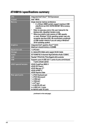
... the chassis. Onboard LED 1-1 5. Atom D410 AT4NM10-I 1-2 Intel® Atom™ D410 processor 1-15 14. USB connectors (10-1 pin USB56, USB78) 1-13 7. System panel connector (10-1 pin F_PANEL) 1-16 16. DO NOT overtighten the screws! Clear RTC RAM (3-pin CLRTC) 1-9 4. Digital audio connector (4-1 pin SPDIF_OUT) 1-17 8. ATX power connectors (24-pin EATXPWR, 4-pin ATX12V) 1-12 11. LVDS connector (30-pin CON1) 1-16 13. Serial ATA connectors (7-pin SATA1, SATA2) 1-13 6. Doing so can damage the motherboard. 1.2.2 Layout contents Connectors/Jumpers/Slots/LED...
... the chassis. Onboard LED 1-1 5. Atom D410 AT4NM10-I 1-2 Intel® Atom™ D410 processor 1-15 14. USB connectors (10-1 pin USB56, USB78) 1-13 7. System panel connector (10-1 pin F_PANEL) 1-16 16. DO NOT overtighten the screws! Clear RTC RAM (3-pin CLRTC) 1-9 4. Digital audio connector (4-1 pin SPDIF_OUT) 1-17 8. ATX power connectors (24-pin EATXPWR, 4-pin ATX12V) 1-12 11. LVDS connector (30-pin CON1) 1-16 13. Serial ATA connectors (7-pin SATA1, SATA2) 1-13 6. Doing so can damage the motherboard. 1.2.2 Layout contents Connectors/Jumpers/Slots/LED...
User Manual
Page 17
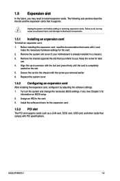
... software drivers for the card. 2. ASUS AT4NM10-I 1-8 Assign an IRQ to the chassis with the slot and press firmly until the card is already installed in a chassis). 3. 1.5 Expansion slot In the future, you may cause you physical injury and damage motherboard components. 1.5.1 Installing an expansion card To install an expansion card: 1. Replace the system cover. 1.5.2 Configuring an expansion card After installing the expansion card, configure it supports. See Chapter 2 for later use . Align the card connector...
... software drivers for the card. 2. ASUS AT4NM10-I 1-8 Assign an IRQ to the chassis with the slot and press firmly until the card is already installed in a chassis). 3. 1.5 Expansion slot In the future, you may cause you physical injury and damage motherboard components. 1.5.1 Installing an expansion card To install an expansion card: 1. Replace the system cover. 1.5.2 Configuring an expansion card After installing the expansion card, configure it supports. See Chapter 2 for later use . Align the card connector...
User Manual
Page 19
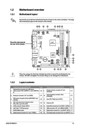
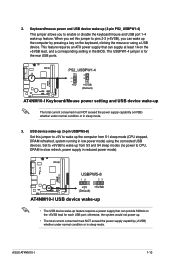
... each USB port; Set to +5VSB to enable or disable the keyboard/mouse and USB port 1-4 wake-up from S1 sleep mode (CPU stopped, DRAM refreshed, system running in the BIOS. This feature requires an ATX power supply that can supply at least 1A on the +5VSB lead, and a corresponding setting in low power mode) using a USB device. Keyboard/mouse power and USB device wake-up (3-pin PS2_USBPW1-4) This jumper allows you to wake up feature. PS2_USBPW1-4 +5V +5VSB (Default) AT4NM10-I USB device wake-up • The USB device wake...
... each USB port; Set to +5VSB to enable or disable the keyboard/mouse and USB port 1-4 wake-up from S1 sleep mode (CPU stopped, DRAM refreshed, system running in the BIOS. This feature requires an ATX power supply that can supply at least 1A on the +5VSB lead, and a corresponding setting in low power mode) using a USB device. Keyboard/mouse power and USB device wake-up (3-pin PS2_USBPW1-4) This jumper allows you to wake up feature. PS2_USBPW1-4 +5V +5VSB (Default) AT4NM10-I USB device wake-up • The USB device wake...
User Manual
Page 21
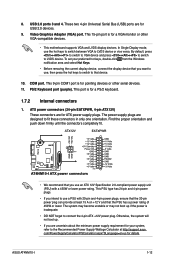
...keyboard. 1.7.2 Internal connectors 1. PS/2 Keyboard port (purple). ASUS AT4NM10-I ATX power connectors • We recommend that device. 10. By default, press ++ to switch to VGA device and press ++ to switch to fit these connectors in only one orientation. This port is for a VGA monitor or other serial devices. 11. ATX power connectors (24-pin EATXPWR, 4-pin ATX12V) These connectors are for ATX power supply plugs. The power supply plugs are uncertain about the minimum power supply requirement for details. This PSU type has 24-pin and 4-pin power plugs. • If you use...
...keyboard. 1.7.2 Internal connectors 1. PS/2 Keyboard port (purple). ASUS AT4NM10-I ATX power connectors • We recommend that device. 10. By default, press ++ to switch to VGA device and press ++ to switch to fit these connectors in only one orientation. This port is for a VGA monitor or other serial devices. 11. ATX power connectors (24-pin EATXPWR, 4-pin ATX12V) These connectors are for ATX power supply plugs. The power supply plugs are uncertain about the minimum power supply requirement for details. This PSU type has 24-pin and 4-pin power plugs. • If you use...
User Manual
Page 27
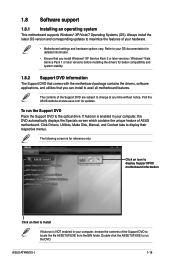
... Support DVD to display their respective menus. Always install the latest OS version and corresponding updates to avail all motherboard features. Visit the ASUS website at any time without notice. ASUS AT4NM10-I 1-18 Click Drivers, Utilities, Make Disk, Manual, and Contact tabs to the optical drive. Click an icon to display Support DVD/ motherboard information Click an item to install If Autorun is enabled in your computer, the DVD automatically displays the Specials screen...
... Support DVD to display their respective menus. Always install the latest OS version and corresponding updates to avail all motherboard features. Visit the ASUS website at any time without notice. ASUS AT4NM10-I 1-18 Click Drivers, Utilities, Make Disk, Manual, and Contact tabs to the optical drive. Click an icon to display Support DVD/ motherboard information Click an item to install If Autorun is enabled in your computer, the DVD automatically displays the Specials screen...

User Manual
Page 28
... motherboard BIOS file to a USB flash disk in case you need to restore the BIOS in the support DVD that allows you to manage, save, and update the motherboard BIOS in Windows® environment. • ASUS Update requires an Internet connection either through a network or an Internet Service Provider (ISP). • This utility is available in the future. b. Quit all Windows® applications before you wish to launch the ASUS Update utility. 2. Place the support DVD...
... motherboard BIOS file to a USB flash disk in case you need to restore the BIOS in the support DVD that allows you to manage, save, and update the motherboard BIOS in Windows® environment. • ASUS Update requires an Internet connection either through a network or an Internet Service Provider (ISP). • This utility is available in the future. b. Quit all Windows® applications before you wish to launch the ASUS Update utility. 2. Place the support DVD...
User Manual
Page 29
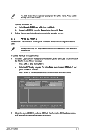
... USB port, then launch EZ Flash 2 in any of updating itself through the Internet. When the correct BIOS file is capable of these two ways: • Press + during POST. • Enter the BIOS setup program. ASUSTek EZ Flash 2 BIOS ROM Utility V3.38 FLASH TYPE: MXIC 25L8005 Current ROM BOARD: AT4NM10-I 2-2 Updating from a file, then click Next. Follow the onscreen instructions to complete the updating process. 2.1.2 ASUS EZ Flash 2 The ASUS EZ Flash 2 feature allows you start using EZ Flash...
... USB port, then launch EZ Flash 2 in any of updating itself through the Internet. When the correct BIOS file is capable of these two ways: • Press + during POST. • Enter the BIOS setup program. ASUSTek EZ Flash 2 BIOS ROM Utility V3.38 FLASH TYPE: MXIC 25L8005 Current ROM BOARD: AT4NM10-I 2-2 Updating from a file, then click Next. Follow the onscreen instructions to complete the updating process. 2.1.2 ASUS EZ Flash 2 The ASUS EZ Flash 2 feature allows you start using EZ Flash...

User Manual
Page 30
... cause system boot failure! Turn off the system after the utility completes the updating process and turn on the system. 2. Select the Load Setup Defaults item under the Exit menu. • This function supports USB flash disks with motherboard models. Ensure to load the BIOS default settings to section 2.8 Exit menu for the BIOS file. Refer to ensure system compatibility and stability. For motherboards without the floppy connector, prepare a USB flash disk before using this utility. The utility automatically checks the devices for details...
... cause system boot failure! Turn off the system after the utility completes the updating process and turn on the system. 2. Select the Load Setup Defaults item under the Exit menu. • This function supports USB flash disks with motherboard models. Ensure to load the BIOS default settings to section 2.8 Exit menu for the BIOS file. Refer to ensure system compatibility and stability. For motherboards without the floppy connector, prepare a USB flash disk before using this utility. The utility automatically checks the devices for details...
User Manual
Page 32
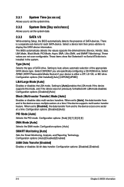
... Technology. These items show Not Detected if no Serial ATA device is a separate sub-menu for each SATA device. These values are specifically configuring a CD-ROM drive. Setting to display the SATA device information. Configuration options: [Disabled] [Auto] PIO Mode [Auto] Selects the PIO mode. Configuration options: [Auto] [0] [1] [2] [3] [4] DMA Mode [Auto] Selects the DMA mode. The BIOS automatically detects the values opposite the dimmed items (Device, Vendor, Size, LBA Mode, Block Mode, PIO Mode, Async DMA, Ultra DMA, and SMART Monitoring). Select ARMD (ATAPI Removable...
... Technology. These items show Not Detected if no Serial ATA device is a separate sub-menu for each SATA device. These values are specifically configuring a CD-ROM drive. Setting to display the SATA device information. Configuration options: [Disabled] [Auto] PIO Mode [Auto] Selects the PIO mode. Configuration options: [Auto] [0] [1] [2] [3] [4] DMA Mode [Auto] Selects the DMA mode. The BIOS automatically detects the values opposite the dimmed items (Device, Vendor, Size, LBA Mode, Block Mode, PIO Mode, Async DMA, Ultra DMA, and SMART Monitoring). Select ARMD (ATAPI Removable...
User Manual
Page 33
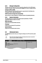
... this menu allow you to malfunction. ASUS AT4NM10-I 2-6 Select an item then press if you an overview of the Advanced menu items. Incorrect field values can cause the system to set or change the settings for the Serial ATA connectors supported by the Southbridge chip. 2.3.4 Storage Configuration The items in this menu. Take caution when changing the settings of the general system specifications. Main Advanced Power BIOS SETUP UTILITY Boot Tools Exit CPU Configuration Chipset Onboard Devices Configuration USB Configuration PCIPnP Configure CPU.
... this menu allow you to malfunction. ASUS AT4NM10-I 2-6 Select an item then press if you an overview of the Advanced menu items. Incorrect field values can cause the system to set or change the settings for the Serial ATA connectors supported by the Southbridge chip. 2.3.4 Storage Configuration The items in this menu. Take caution when changing the settings of the general system specifications. Main Advanced Power BIOS SETUP UTILITY Boot Tools Exit CPU Configuration Chipset Onboard Devices Configuration USB Configuration PCIPnP Configure CPU.
User Manual
Page 34
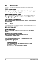
... options: [Disabled] [Enabled] Execute-Disable Bit Capability [Enabled] Allows you to enable or disable the No-Execution Page Protection Technology. Configuration options: [Enabled] [Disabled] Initiate Graphic Adapter [IGD] Allows you to use as the primary boot device. Configuration options: [DVMT Mode] DVMT/FIXED Memory [256MB] Configuration options: [128MB] [256MB] [Maximum DVMT] 2-7 Chapter 2: BIOS information North Bridge Configuration DRAM Frequency [Auto] Allows you to decide which graphics controller to set the DDR2 operating frequency. Configuration options: [Auto...
... options: [Disabled] [Enabled] Execute-Disable Bit Capability [Enabled] Allows you to enable or disable the No-Execution Page Protection Technology. Configuration options: [Enabled] [Disabled] Initiate Graphic Adapter [IGD] Allows you to use as the primary boot device. Configuration options: [DVMT Mode] DVMT/FIXED Memory [256MB] Configuration options: [128MB] [256MB] [Maximum DVMT] 2-7 Chapter 2: BIOS information North Bridge Configuration DRAM Frequency [Auto] Allows you to decide which graphics controller to set the DDR2 operating frequency. Configuration options: [Auto...
User Manual
Page 35
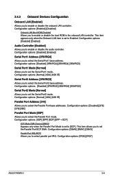
... or disable the onboard LAN controller. 2.4.3 Onboard Devices Configuration Onboard LAN [Enabled] Allows you to select parallel port IRQ. Configuration options: [Enabled] [Disabled] Onboard LAN Boot ROM [Disabled] Allows you to select the Serial Port2 base address. Configuration options: [Normal] [IrDA] [ASK IR] Serial Port2 Address [2F8/IRQ3] Allows you to Enabled. This item allows you to enable or disable the boot ROM in the onboard LAN controller. This item appears only when the Onboard LAN item is set the Serial Port1 mode. Configuration options: [IRQ5] [IRQ7] ASUS AT4NM10...
... or disable the onboard LAN controller. 2.4.3 Onboard Devices Configuration Onboard LAN [Enabled] Allows you to select parallel port IRQ. Configuration options: [Enabled] [Disabled] Onboard LAN Boot ROM [Disabled] Allows you to select the Serial Port2 base address. Configuration options: [Normal] [IrDA] [ASK IR] Serial Port2 Address [2F8/IRQ3] Allows you to Enabled. This item allows you to enable or disable the boot ROM in the onboard LAN controller. This item appears only when the Onboard LAN item is set the Serial Port1 mode. Configuration options: [IRQ5] [IRQ7] ASUS AT4NM10...
User Manual
Page 36
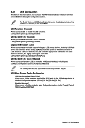
...no USB device is plugged. Configuration options: [Auto] [Floppy] [Forced FDD] [Hard Disk] [CDROM] 2-9 Chapter 2: BIOS information Configuration options: [Enabled] [Disabled] Legacy USB Support [Auto] Allows you to enable or disable support for the USB storage device to change the USB-related features. If detected, the USB controller legacy mode is disabled. Configuration options: [FullSpeed] [HiSpeed] The following items may only appear when a USB storage device is detected, the item shows None. USB Functions [Enabled] Allows you to disable or enable the USB functions...
...no USB device is plugged. Configuration options: [Auto] [Floppy] [Forced FDD] [Hard Disk] [CDROM] 2-9 Chapter 2: BIOS information Configuration options: [Enabled] [Disabled] Legacy USB Support [Auto] Allows you to enable or disable support for the USB storage device to change the USB-related features. If detected, the USB controller legacy mode is disabled. Configuration options: [FullSpeed] [HiSpeed] The following items may only appear when a USB storage device is detected, the item shows None. USB Functions [Enabled] Allows you to disable or enable the USB functions...
User Manual
Page 37
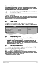
Take caution when changing the settings of the PCI PnP menu items. Incorrect field values can cause the system to RAM) sleep state (default). Plug and Play O/S [No] When set to Enabled, the ACPI APIC table pointer is included in the RSDT pointer list. Main Advanced Power BIOS SETUP UTILITY Boot Tools Exit Suspend Mode ACPI 2.0 Support ACPI APIC Support Control EuP [S3 only] [Disabled] [Enabled] [Disabled] APM Configuration Hardware Monitor Select the ACPI state used for system suspend. In S3 sleep state...
Take caution when changing the settings of the PCI PnP menu items. Incorrect field values can cause the system to RAM) sleep state (default). Plug and Play O/S [No] When set to Enabled, the ACPI APIC table pointer is included in the RSDT pointer list. Main Advanced Power BIOS SETUP UTILITY Boot Tools Exit Suspend Mode ACPI 2.0 Support ACPI APIC Support Control EuP [S3 only] [Disabled] [Enabled] [Disabled] APM Configuration Hardware Monitor Select the ACPI state used for system suspend. In S3 sleep state...
User Manual
Page 38
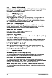
... keys on the keyboard to the motherboard, the field shows N/A. Configuration options: [Disabled] [Enabled] 2.5.6 Hardware Monitor CPU/MB Temperature [xxxºC/xxxºF] or [Ignored] The onboard hardware monitor automatically detects and displays the CPU/motherboard temperature. Configuration options: [Disabled] [Enabled] 2.5.5 APM Configuration Restore on the system. 2.5.4 Control EuP [Disabled] Enables or disables the Energy Using Products (EuP) Ready function. Configuration options: [Disabled] [Enabled] Power On By PME [Disabled] Enables or disables PME wake from sleep...
... keys on the keyboard to the motherboard, the field shows N/A. Configuration options: [Disabled] [Enabled] 2.5.6 Hardware Monitor CPU/MB Temperature [xxxºC/xxxºF] or [Ignored] The onboard hardware monitor automatically detects and displays the CPU/motherboard temperature. Configuration options: [Disabled] [Enabled] 2.5.5 APM Configuration Restore on the system. 2.5.4 Control EuP [Disabled] Enables or disables the Energy Using Products (EuP) Ready function. Configuration options: [Disabled] [Enabled] Power On By PME [Disabled] Enables or disables PME wake from sleep...
User Manual
Page 39
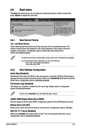
... AddOn ROM Display Mode [Force BIOS] Sets the display mode for the F1 key to display the sub-menu. Configuration options: [Disabled] [Enabled] ASUS AT4NM10-I 2-12 Select an item then press to be pressed when error occurs. Configuration options: [Removable Dev.] [Hard Drive] [ATAPI CD-ROM] [Disabled] • To select the boot device during system startup, press when ASUS Logo appears. • To access Windows® OS in Safe Mode, do any of devices installed in the system. Main Advanced Power BIOS SETUP UTILITY Boot Tools Exit Boot Settings Boot Device Priority Boot Settings...
... AddOn ROM Display Mode [Force BIOS] Sets the display mode for the F1 key to display the sub-menu. Configuration options: [Disabled] [Enabled] ASUS AT4NM10-I 2-12 Select an item then press to be pressed when error occurs. Configuration options: [Removable Dev.] [Hard Drive] [ATAPI CD-ROM] [Disabled] • To select the boot device during system startup, press when ASUS Logo appears. • To access Windows® OS in Safe Mode, do any of devices installed in the system. Main Advanced Power BIOS SETUP UTILITY Boot Tools Exit Boot Settings Boot Device Priority Boot Settings...
User Manual
Page 41
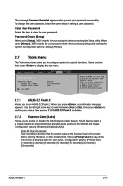
... Timer Reset User Data AI NET2 [Auto] [10 Seconds] [No] Press ENTER to run ASUS EZ Flash 2. See section 2.1.2 ASUS EZ Flash 2 for details. 2.7.2 Express Gate [Auto] Allows you press , a confirmation message appears. Choose [Prompt User] to [Always], BIOS checks for user password when accessing the Setup utility. To change the user password, follow the same steps in setting a user password. Password Check [Setup] When set to stay at the Express Gate's first screen before starting Windows or other installed OS. Configuration options: [Enabled] [Disabled] [Auto] Enter...
... Timer Reset User Data AI NET2 [Auto] [10 Seconds] [No] Press ENTER to run ASUS EZ Flash 2. See section 2.1.2 ASUS EZ Flash 2 for details. 2.7.2 Express Gate [Auto] Allows you press , a confirmation message appears. Choose [Prompt User] to [Always], BIOS checks for user password when accessing the Setup utility. To change the user password, follow the same steps in setting a user password. Password Check [Setup] When set to stay at the Express Gate's first screen before starting Windows or other installed OS. Configuration options: [Enabled] [Disabled] [Auto] Enter...


