
User Manual
Page 1
AT4NM10-I Motherboard
AT4NM10-I Motherboard

User Manual
Page 2
...translated into any language in the GPL) for the GPL Software, and/or the complete corresponding source code of ASUSTeK Computer Inc. ("ASUS"). ASUS ASSUMES NO RESPONSIBILITY OR LIABILITY FOR ANY ERRORS OR INACCURACIES THAT MAY APPEAR IN THIS MANUAL, INCLUDING THE PRODUCTS AND SOFTWARE DESCRIBED IN... is licensed under the General Public License ("GPL") and under the Lesser General Public License Version ("LGPL"). ii IN NO EVENT SHALL ASUS, ITS DIRECTORS, OFFICERS, EMPLOYEES OR AGENTS BE LIABLE FOR ANY INDIRECT, SPECIAL, INCIDENTAL, OR CONSEQUENTIAL DAMAGES (INCLUDING DAMAGES FOR LOSS OF...
...translated into any language in the GPL) for the GPL Software, and/or the complete corresponding source code of ASUSTeK Computer Inc. ("ASUS"). ASUS ASSUMES NO RESPONSIBILITY OR LIABILITY FOR ANY ERRORS OR INACCURACIES THAT MAY APPEAR IN THIS MANUAL, INCLUDING THE PRODUCTS AND SOFTWARE DESCRIBED IN... is licensed under the General Public License ("GPL") and under the Lesser General Public License Version ("LGPL"). ii IN NO EVENT SHALL ASUS, ITS DIRECTORS, OFFICERS, EMPLOYEES OR AGENTS BE LIABLE FOR ANY INDIRECT, SPECIAL, INCIDENTAL, OR CONSEQUENTIAL DAMAGES (INCLUDING DAMAGES FOR LOSS OF...
User Manual
Page 3
Contents Notices...v Safety information vi About this guide vi AT4NM10-I specifications summary viii Chapter 1: Product introduction 1.1 Before you proceed 1-1 1.2 Motherboard overview 1-2 1.2.1 Motherboard layout 1-2 1.2.2 Layout contents 1-2 1.3 Central Processing Unit (CPU 1-3 1.4 System memory 1-3 1.4.1... support 1-18 1.8.1 Installing an operating system 1-18 1.8.2 Support DVD information 1-18 Chapter 2: BIOS information 2.1 Managing and updating your BIOS 2-1 2.1.1 ASUS Update utility 2-1 2.1.2 ASUS EZ Flash 2 2-2 2.1.3 ASUS CrashFree BIOS 2-3 2.2 BIOS setup program 2-4 iii
Contents Notices...v Safety information vi About this guide vi AT4NM10-I specifications summary viii Chapter 1: Product introduction 1.1 Before you proceed 1-1 1.2 Motherboard overview 1-2 1.2.1 Motherboard layout 1-2 1.2.2 Layout contents 1-2 1.3 Central Processing Unit (CPU 1-3 1.4 System memory 1-3 1.4.1... support 1-18 1.8.1 Installing an operating system 1-18 1.8.2 Support DVD information 1-18 Chapter 2: BIOS information 2.1 Managing and updating your BIOS 2-1 2.1.1 ASUS Update utility 2-1 2.1.2 ASUS EZ Flash 2 2-2 2.1.3 ASUS CrashFree BIOS 2-3 2.2 BIOS setup program 2-4 iii

User Manual
Page 4
... 2.5.4 Control EuP 2-11 2.5.5 APM Configuration 2-11 2.5.6 Hardware Monitor 2-11 2.6 Boot menu 2-12 2.6.1 Boot Device Priority 2-12 2.6.2 Boot Settings Configuration 2-12 2.6.3 Security 2-13 2.7 Tools menu 2-14 2.7.1 ASUS EZ Flash 2 2-14 2.7.2 Express Gate 2-14 2.7.3 AI NET 2 2-15 2.8 Exit menu 2-15 iv
... 2.5.4 Control EuP 2-11 2.5.5 APM Configuration 2-11 2.5.6 Hardware Monitor 2-11 2.6 Boot menu 2-12 2.6.1 Boot Device Priority 2-12 2.6.2 Boot Settings Configuration 2-12 2.6.3 Security 2-13 2.7 Tools menu 2-14 2.7.1 ASUS EZ Flash 2 2-14 2.7.2 Express Gate 2-14 2.7.3 AI NET 2 2-15 2.8 Exit menu 2-15 iv

User Manual
Page 5
... used in the Radio Interference Regulations of the Canadian Department of Chemicals) regulatory framework, we published the chemical substances in our products at ASUS REACH website at http://green.asus.com/english/REACH.htm. These limits are designed to this equipment. This class B digital apparatus complies with Part 15 of the FCC...
... used in the Radio Interference Regulations of the Canadian Department of Chemicals) regulatory framework, we published the chemical substances in our products at ASUS REACH website at http://green.asus.com/english/REACH.htm. These limits are designed to this equipment. This class B digital apparatus complies with Part 15 of the FCC...

User Manual
Page 6
Operation safety • Before installing the motherboard and adding devices on a stable surface. • If you encounter technical problems with the package. • Before using the product, ensure that all cables are correctly connected and the power cables are using, contact your retailer. vi Safety information Electrical safety • To prevent electric shock hazard, disconnect the power cable from the electric outlet before relocating the system. • When adding or removing devices to or from the motherboard, ensure that all power cables are unplugged. • ...
Operation safety • Before installing the motherboard and adding devices on a stable surface. • If you encounter technical problems with the package. • Before using the product, ensure that all cables are correctly connected and the power cables are using, contact your retailer. vi Safety information Electrical safety • To prevent electric shock hazard, disconnect the power cable from the electric outlet before relocating the system. • When adding or removing devices to or from the motherboard, ensure that all power cables are unplugged. • ...

User Manual
Page 7
... provides updated information on ASUS hardware and software products. These documents are linked with a plus sign (+). Keys enclosed in this manual. IMPORTANT: Instructions that you MUST follow to the following ... more keys simultaneously, the key names are not part of the following sources for additional information and for product and software updates. 1. Used to the ASUS contact information. 2. Example: ++ vii If you must press the Enter or Return key. Refer to emphasize a word or a phrase. Typography Bold text Italics ++ Indicates a menu...
... provides updated information on ASUS hardware and software products. These documents are linked with a plus sign (+). Keys enclosed in this manual. IMPORTANT: Instructions that you MUST follow to the following ... more keys simultaneously, the key names are not part of the following sources for additional information and for product and software updates. 1. Used to the ASUS contact information. 2. Example: ++ vii If you must press the Enter or Return key. Refer to emphasize a word or a phrase. Typography Bold text Italics ++ Indicates a menu...
User Manual
Page 8
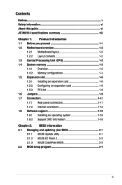
...Supports up to 8 USB 2.0/1.1 ports (4 ports at mid-board, 4 ports at back panel) ASUS CrashFree BIOS 3 ASUS EZ Flash 2 ASUS MyLogo 2™ ASUS AI NET 2 ASUS Express Gate 1 x PS/2 Keyboard port 1 x PS/2 Mouse port 1 x COM port ... 2.0/1.1 ports 6-channel audio I specifications summary CPU Chipset Memory Graphics Expansion slot Storage Audio LAN USB ASUS special features Rear panel ports Integrated Intel® Atom™ D410 processor Intel® NM10 Single ...ECC DDR2 800/667 MHz memory modules * Refer to www.asus.com or this user manual for the Memory QVL (Qualified Vendors Lists). **...
...Supports up to 8 USB 2.0/1.1 ports (4 ports at mid-board, 4 ports at back panel) ASUS CrashFree BIOS 3 ASUS EZ Flash 2 ASUS MyLogo 2™ ASUS AI NET 2 ASUS Express Gate 1 x PS/2 Keyboard port 1 x PS/2 Mouse port 1 x COM port ... 2.0/1.1 ports 6-channel audio I specifications summary CPU Chipset Memory Graphics Expansion slot Storage Audio LAN USB ASUS special features Rear panel ports Integrated Intel® Atom™ D410 processor Intel® NM10 Single ...ECC DDR2 800/667 MHz memory modules * Refer to www.asus.com or this user manual for the Memory QVL (Qualified Vendors Lists). **...
User Manual
Page 9
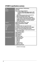
AT4NM10-I specifications summary Internal connectors BIOS features Accessories Support DVD contents Form Factor 2 x USB 2.0/1.1 connector supports additional 4 USB 2.0/1.1 ports 1 x CPU fan connector 1 x Chassis fan connector 1 x Chassis ... power connector 1 x 4-pin ATX 12V power connector 8 Mb Flash ROM, AMI BIOS, PnP, DMI2.0, WfM2.0, SMBIOS 2.5 1 x Serial ATA cable 1 x I/O shield 1 x User Manual Drivers ASUS PC Probe II ASUS Update Anti-virus software (OEM version) Mini ITX form factor: 6.75 in x 6.75 in (17.1cm x 17.1cm) * Specifications are subject to change without...
AT4NM10-I specifications summary Internal connectors BIOS features Accessories Support DVD contents Form Factor 2 x USB 2.0/1.1 connector supports additional 4 USB 2.0/1.1 ports 1 x CPU fan connector 1 x Chassis fan connector 1 x Chassis ... power connector 1 x 4-pin ATX 12V power connector 8 Mb Flash ROM, AMI BIOS, PnP, DMI2.0, WfM2.0, SMBIOS 2.5 1 x Serial ATA cable 1 x I/O shield 1 x User Manual Drivers ASUS PC Probe II ASUS Update Anti-virus software (OEM version) Mini ITX form factor: 6.75 in x 6.75 in (17.1cm x 17.1cm) * Specifications are subject to change without...
User Manual
Page 10
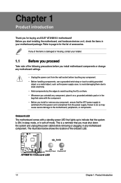
...supply case, to avoid damaging them due to static electricity. • Hold components by the edges to page ix for buying an ASUS® AT4NM10-I Onboard LED 1-1 Chapter 1: Product introduction Refer to avoid touching the ICs on them. • Whenever you uninstall any component, ...ensure that the ATX power supply is a reminder that lights up to the motherboard, peripherals, or components. This is switched off mode. AT4NM10-I AT4NM10-I motherboard! Chapter 1 Product introduction Thank you for the list of the onboard LED. Onboard LED The motherboard comes with the component. &#...
...supply case, to avoid damaging them due to static electricity. • Hold components by the edges to page ix for buying an ASUS® AT4NM10-I Onboard LED 1-1 Chapter 1: Product introduction Refer to avoid touching the ICs on them. • Whenever you uninstall any component, ...ensure that the ATX power supply is a reminder that lights up to the motherboard, peripherals, or components. This is switched off mode. AT4NM10-I AT4NM10-I motherboard! Chapter 1 Product introduction Thank you for the list of the onboard LED. Onboard LED The motherboard comes with the component. &#...
User Manual
Page 11
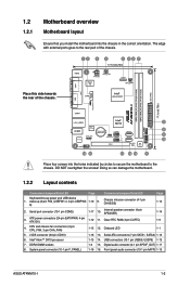
...17 10. Onboard LED 1-1 5. Digital audio connector (4-1 pin SPDIF_OUT) 1-17 8. Front panel audio connector (10-1 pin AAFP) 1-15 ASUS AT4NM10-I Place four screws into the chassis in the correct orientation. Internal speaker connector (4-pin SPEAKER) 1-14 3. ATX power connectors (24-pin EATXPWR.... 1.2.2 Layout contents Connectors/Jumpers/Slots/LED Page Connectors/Jumpers/Slots/LED Page Keyboard/mouse power and USB device 1. Atom D410 AT4NM10-I 1-2 CPU and chassis fan connectors (3-pin CPU_FAN, 3-pin CHA_FAN) 1-15 12. The edge with external ports goes to ...
...17 10. Onboard LED 1-1 5. Digital audio connector (4-1 pin SPDIF_OUT) 1-17 8. Front panel audio connector (10-1 pin AAFP) 1-15 ASUS AT4NM10-I Place four screws into the chassis in the correct orientation. Internal speaker connector (4-pin SPEAKER) 1-14 3. ATX power connectors (24-pin EATXPWR.... 1.2.2 Layout contents Connectors/Jumpers/Slots/LED Page Connectors/Jumpers/Slots/LED Page Keyboard/mouse power and USB device 1. Atom D410 AT4NM10-I 1-2 CPU and chassis fan connectors (3-pin CPU_FAN, 3-pin CHA_FAN) 1-15 12. The edge with external ports goes to ...
User Manual
Page 12
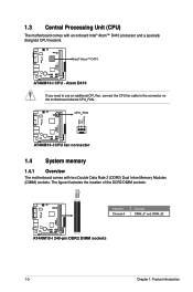
...DDR2 DIMM sockets 1-3 Chapter 1: Product introduction The figure illustrates the location of the DDR2 DIMM sockets: Channel Channel A Sockets DIMM_A1 and DIMM_A2 AT4NM10-I AT4NM10-I CPU fan connector 1.4 System memory 1.4.1 Overview The motherboard comes with an onboard Intel® Atom™ D410 processor and a specially ...to use an additional CPU fan, connect the CPU fan cable to the connector on the motherboard labeled CPU_FAN. D410 AT4NM10-I 1.3 Central Processing Unit (CPU) The motherboard comes with two Double Data Rate 2 (DDR2) Dual Inline Memory Modules (DIMM) sockets...
...DDR2 DIMM sockets 1-3 Chapter 1: Product introduction The figure illustrates the location of the DDR2 DIMM sockets: Channel Channel A Sockets DIMM_A1 and DIMM_A2 AT4NM10-I AT4NM10-I CPU fan connector 1.4 System memory 1.4.1 Overview The motherboard comes with an onboard Intel® Atom™ D410 processor and a specially ...to use an additional CPU fan, connect the CPU fan cable to the connector on the motherboard labeled CPU_FAN. D410 AT4NM10-I 1.3 Central Processing Unit (CPU) The motherboard comes with two Double Data Rate 2 (DDR2) Dual Inline Memory Modules (DIMM) sockets...
User Manual
Page 13
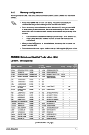
... DS Brand Chip NO. Use a maximum of 3GB system memory if you install 4GB memory on the next page) ASUS AT4NM10-I Motherboard Qualified Vendors Lists (QVL) DDR2-667 MHz capability Vendor Part No. AT4NM10-I 1-4 Install a 64-bit Windows® OS when you want to the memory address limitation on 32-bit Windows®...
... DS Brand Chip NO. Use a maximum of 3GB system memory if you install 4GB memory on the next page) ASUS AT4NM10-I Motherboard Qualified Vendors Lists (QVL) DDR2-667 MHz capability Vendor Part No. AT4NM10-I 1-4 Install a 64-bit Windows® OS when you want to the memory address limitation on 32-bit Windows®...

User Manual
Page 15
...;• 5 - •• - - •• 6 - •• 6 - •• - - •• 6 - •• 6 - •• - - •• 4 1.8V • • (continued on the next page) ASUS AT4NM10-I 1-6 GEIL GEIL GEIL GEIL GEIL GEIL GEIL GEIL GEIL GEIL GEIL GEIL GEIL GEIL GEIL GEIL Kingmax Kingmax Kingston Kingston Kingston Kingston Kingston Kingston OCZ...
...;• 5 - •• - - •• 6 - •• 6 - •• - - •• 6 - •• 6 - •• - - •• 4 1.8V • • (continued on the next page) ASUS AT4NM10-I 1-6 GEIL GEIL GEIL GEIL GEIL GEIL GEIL GEIL GEIL GEIL GEIL GEIL GEIL GEIL GEIL GEIL Kingmax Kingmax Kingston Kingston Kingston Kingston Kingston Kingston OCZ...

User Manual
Page 16
... U2S12D30TP-8E - - 2048MB DS UMAX U2S24D30TP-8E 5 - 512MB SS V-Data VD29608A8A-25EG20813 - - 1024MB DS Samsung K4T51083QE - - 2048MB DS Hynix H5PS1G83EFRS6C 852AK - - Visit the ASUS website at www.asus.com for the latest QVL. 1-7 Chapter 1: Product introduction SS ELPIDA E1108ACBG-8E-E SS Micron 7HD22 D9GMH DS Transced TQ123PJF8F0801 DS Transcend TQ123YBF8 T0747 DS...
... U2S12D30TP-8E - - 2048MB DS UMAX U2S24D30TP-8E 5 - 512MB SS V-Data VD29608A8A-25EG20813 - - 1024MB DS Samsung K4T51083QE - - 2048MB DS Hynix H5PS1G83EFRS6C 852AK - - Visit the ASUS website at www.asus.com for the latest QVL. 1-7 Chapter 1: Product introduction SS ELPIDA E1108ACBG-8E-E SS Micron 7HD22 D9GMH DS Transced TQ123PJF8F0801 DS Transcend TQ123YBF8 T0747 DS...
User Manual
Page 17
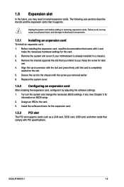
... card is already installed in a chassis). 3. Remove the bracket opposite the slot that came with the screw you removed earlier. 6. See Chapter 2 for later use . ASUS AT4NM10-I 1-8 Unplug the power cord before adding or removing expansion cards. Replace the system cover. 1.5.2 Configuring an expansion card After installing the expansion card, configure it...
... card is already installed in a chassis). 3. Remove the bracket opposite the slot that came with the screw you removed earlier. 6. See Chapter 2 for later use . ASUS AT4NM10-I 1-8 Unplug the power cord before adding or removing expansion cards. Replace the system cover. 1.5.2 Configuring an expansion card After installing the expansion card, configure it...
User Manual
Page 18
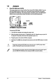
... CMOS memory of date, time, and system setup parameters by erasing the CMOS RTC RAM data. Turn OFF the computer and unplug the power cord. 2. AT4NM10-I Clear RTC RAM To erase the RTC RAM: 1. Removing the cap will cause system boot failure! Keep the cap on CLRTC jumper default position. After... (3-pin CLRTC) This jumper allows you to clear the Real Time Clock (RTC) RAM in CMOS, which include system setup information such as system passwords. AT4NM10-I 1.6 Jumpers 1. Plug the power cord and turn ON the computer. 4.
... CMOS memory of date, time, and system setup parameters by erasing the CMOS RTC RAM data. Turn OFF the computer and unplug the power cord. 2. AT4NM10-I Clear RTC RAM To erase the RTC RAM: 1. Removing the cap will cause system boot failure! Keep the cap on CLRTC jumper default position. After... (3-pin CLRTC) This jumper allows you to clear the Real Time Clock (RTC) RAM in CMOS, which include system setup information such as system passwords. AT4NM10-I 1.6 Jumpers 1. Plug the power cord and turn ON the computer. 4.
User Manual
Page 19
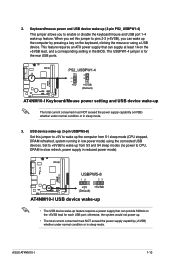
The USBPW1-4 jumper is for each USB port; AT4NM10-I AT4NM10-I 1-10 ASUS AT4NM10-I USB device wake-up • The USB device wake-up ... to enable or disable the keyboard/mouse and USB port 1-4 wake-up feature. PS2_USBPW1-4 +5V +5VSB (Default) AT4NM10-I 12 23 2. otherwise, the system would not power up. • The total current consumed must NOT exceed the... power supply capability (+5VSB) whether under normal condition or in sleep mode. AT4NM10-I Keyboard/Mouse power setting and USB device wake-up The total current consumed must NOT exceed the power ...
The USBPW1-4 jumper is for each USB port; AT4NM10-I AT4NM10-I 1-10 ASUS AT4NM10-I USB device wake-up • The USB device wake-up ... to enable or disable the keyboard/mouse and USB port 1-4 wake-up feature. PS2_USBPW1-4 +5V +5VSB (Default) AT4NM10-I 12 23 2. otherwise, the system would not power up. • The total current consumed must NOT exceed the... power supply capability (+5VSB) whether under normal condition or in sleep mode. AT4NM10-I Keyboard/Mouse power setting and USB device wake-up The total current consumed must NOT exceed the power ...

User Manual
Page 20
Line In port (light blue). This port connects to the audio configuration table below for the function of this port becomes Front Speaker Out. 6. USB 2.0 ports 1 and 2. These two 4-pin Universal Serial Bus (USB) ports are for a PS/2 mouse. 2. This 25-pin port connects a parallel printer, a scanner, or other audio sources. 5. LAN (RJ-45) port. Refer to a headphone or a speaker. In the 4-channel and 6-channel configurations, the function of the audio ports in 2, 4, or 6-channel configuration. Audio 2, 4, or 6-channel configuration Port Light Blue Lime Pink Headset 2-...
Line In port (light blue). This port connects to the audio configuration table below for the function of this port becomes Front Speaker Out. 6. USB 2.0 ports 1 and 2. These two 4-pin Universal Serial Bus (USB) ports are for a PS/2 mouse. 2. This 25-pin port connects a parallel printer, a scanner, or other audio sources. 5. LAN (RJ-45) port. Refer to a headphone or a speaker. In the 4-channel and 6-channel configurations, the function of the audio ports in 2, 4, or 6-channel configuration. Audio 2, 4, or 6-channel configuration Port Light Blue Lime Pink Headset 2-...
User Manual
Page 21
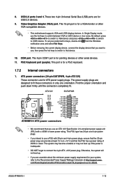
...-pin port is for a VGA monitor or other serial devices. 11. This port is for a PS/2 keyboard. 1.7.2 Internal connectors 1. ASUS AT4NM10-I ATX power connectors • We recommend that you are for pointing devices or other VGA-compatible devices. • This motherboard supports VGA ... By default, press ++ to switch to VGA device and press ++ to switch to that the 20-pin power plug can provide at http://support.asus. COM port. PS/2 Keyboard port (purple). 8. Find the proper orientation and push down firmly until the connectors completely fit. Otherwise, the system ...
...-pin port is for a VGA monitor or other serial devices. 11. This port is for a PS/2 keyboard. 1.7.2 Internal connectors 1. ASUS AT4NM10-I ATX power connectors • We recommend that you are for pointing devices or other VGA-compatible devices. • This motherboard supports VGA ... By default, press ++ to switch to VGA device and press ++ to switch to that the 20-pin power plug can provide at http://support.asus. COM port. PS/2 Keyboard port (purple). 8. Find the proper orientation and push down firmly until the connectors completely fit. Otherwise, the system ...