User Manual
Page 3
Contents Notices...v Safety information vi About this guide vi AT4NM10-I specifications summary viii Chapter 1: Product introduction 1.1 Before you proceed 1-1 1.2 Motherboard overview 1-2 1.2.1 Motherboard layout 1-2 1.2.2 Layout contents 1-2 1.3 Central Processing Unit (CPU 1-3 1.4 System memory 1-3 1.4.1... support 1-18 1.8.1 Installing an operating system 1-18 1.8.2 Support DVD information 1-18 Chapter 2: BIOS information 2.1 Managing and updating your BIOS 2-1 2.1.1 ASUS Update utility 2-1 2.1.2 ASUS EZ Flash 2 2-2 2.1.3 ASUS CrashFree BIOS 2-3 2.2 BIOS setup program 2-4 iii
Contents Notices...v Safety information vi About this guide vi AT4NM10-I specifications summary viii Chapter 1: Product introduction 1.1 Before you proceed 1-1 1.2 Motherboard overview 1-2 1.2.1 Motherboard layout 1-2 1.2.2 Layout contents 1-2 1.3 Central Processing Unit (CPU 1-3 1.4 System memory 1-3 1.4.1... support 1-18 1.8.1 Installing an operating system 1-18 1.8.2 Support DVD information 1-18 Chapter 2: BIOS information 2.1 Managing and updating your BIOS 2-1 2.1.1 ASUS Update utility 2-1 2.1.2 ASUS EZ Flash 2 2-2 2.1.3 ASUS CrashFree BIOS 2-3 2.2 BIOS setup program 2-4 iii
User Manual
Page 8
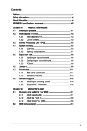
We recommend a maximum of 4GB capacity or more, Windows® 32-bit operating system may only recognize less than 3GB. AT4NM10-I /O ports (continued on the next page) viii Integrated Intel® graphics Atom™ D410 Maximum shared memory of 256MB 1 x PCI slot... CODEC Realtek® RTL8112L PCIe Gigabit LAN controller Supports up to 8 USB 2.0/1.1 ports (4 ports at mid-board, 4 ports at back panel) ASUS CrashFree BIOS 3 ASUS EZ Flash 2 ASUS MyLogo 2™ ASUS AI NET 2 ASUS Express Gate 1 x PS/2 Keyboard port 1 x PS/2 Mouse port 1 x COM port 1 x VGA port 1 x LPT port 1 x LAN (RJ-45) ...
We recommend a maximum of 4GB capacity or more, Windows® 32-bit operating system may only recognize less than 3GB. AT4NM10-I /O ports (continued on the next page) viii Integrated Intel® graphics Atom™ D410 Maximum shared memory of 256MB 1 x PCI slot... CODEC Realtek® RTL8112L PCIe Gigabit LAN controller Supports up to 8 USB 2.0/1.1 ports (4 ports at mid-board, 4 ports at back panel) ASUS CrashFree BIOS 3 ASUS EZ Flash 2 ASUS MyLogo 2™ ASUS AI NET 2 ASUS Express Gate 1 x PS/2 Keyboard port 1 x PS/2 Mouse port 1 x COM port 1 x VGA port 1 x LPT port 1 x LAN (RJ-45) ...
User Manual
Page 9
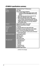
ix AT4NM10-I specifications summary Internal connectors BIOS features Accessories Support DVD contents Form Factor 2 x USB 2.0/1.1 connector supports additional 4 USB 2.0/1.1 ports 1 x CPU fan connector 1 x Chassis fan connector 1 x Chassis ... power connector 1 x 4-pin ATX 12V power connector 8 Mb Flash ROM, AMI BIOS, PnP, DMI2.0, WfM2.0, SMBIOS 2.5 1 x Serial ATA cable 1 x I/O shield 1 x User Manual Drivers ASUS PC Probe II ASUS Update Anti-virus software (OEM version) Mini ITX form factor: 6.75 in x 6.75 in (17.1cm x 17.1cm) * Specifications are subject to change without...
ix AT4NM10-I specifications summary Internal connectors BIOS features Accessories Support DVD contents Form Factor 2 x USB 2.0/1.1 connector supports additional 4 USB 2.0/1.1 ports 1 x CPU fan connector 1 x Chassis fan connector 1 x Chassis ... power connector 1 x 4-pin ATX 12V power connector 8 Mb Flash ROM, AMI BIOS, PnP, DMI2.0, WfM2.0, SMBIOS 2.5 1 x Serial ATA cable 1 x I/O shield 1 x User Manual Drivers ASUS PC Probe II ASUS Update Anti-virus software (OEM version) Mini ITX form factor: 6.75 in x 6.75 in (17.1cm x 17.1cm) * Specifications are subject to change without...
User Manual
Page 10
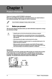
Onboard LED The motherboard comes with a standby power LED that lights up to page ix for buying an ASUS® AT4NM10-I Onboard LED 1-1 Chapter 1: Product introduction Before you start installing the motherboard, and hardware devices on it on them due to static electricity. ...with the component. • Before you must shut down the system and unplug the power cable before removing or plugging in any motherboard component. AT4NM10-I AT4NM10-I motherboard! If any of the items is damaged or missing, contact your retailer. 1.1 Before you proceed Take note of the following precautions ...
Onboard LED The motherboard comes with a standby power LED that lights up to page ix for buying an ASUS® AT4NM10-I Onboard LED 1-1 Chapter 1: Product introduction Before you start installing the motherboard, and hardware devices on it on them due to static electricity. ...with the component. • Before you must shut down the system and unplug the power cable before removing or plugging in any motherboard component. AT4NM10-I AT4NM10-I motherboard! If any of the items is damaged or missing, contact your retailer. 1.1 Before you proceed Take note of the following precautions ...
User Manual
Page 11
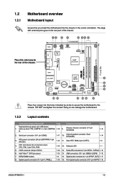
...pin CPU_FAN, 3-pin CHA_FAN) 1-15 12. DDR2 DIMM sockets 1-3 15. Front panel audio connector (10-1 pin AAFP) 1-15 ASUS AT4NM10-I Place four screws into the chassis in the correct orientation. 1.2 1.2.1 Motherboard overview Motherboard layout Ensure that you install the motherboard into ...) 1-17 10. LVDS connector (30-pin CON1) 1-16 13. USB connectors (10-1 pin USB56, USB78) 1-13 7. Atom D410 AT4NM10-I 1-2 Doing so can damage the motherboard. 1.2.2 Layout contents Connectors/Jumpers/Slots/LED Page Connectors/Jumpers/Slots/LED Page Keyboard/mouse power and ...
...pin CPU_FAN, 3-pin CHA_FAN) 1-15 12. DDR2 DIMM sockets 1-3 15. Front panel audio connector (10-1 pin AAFP) 1-15 ASUS AT4NM10-I Place four screws into the chassis in the correct orientation. 1.2 1.2.1 Motherboard overview Motherboard layout Ensure that you install the motherboard into ...) 1-17 10. LVDS connector (30-pin CON1) 1-16 13. USB connectors (10-1 pin USB56, USB78) 1-13 7. Atom D410 AT4NM10-I 1-2 Doing so can damage the motherboard. 1.2.2 Layout contents Connectors/Jumpers/Slots/LED Page Connectors/Jumpers/Slots/LED Page Keyboard/mouse power and ...
User Manual
Page 13
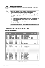
... - • - • - • 1.8V • 1.8V • - • - • - • - • - • - • - • - • - • - • - • - • - • (continued on the next page) ASUS AT4NM10-I Motherboard Qualified Vendors Lists (QVL) DDR2-667 MHz capability Vendor Part No. For optimum compatibility, it is less than 4GB. • This motherboard does not... install 512MB, 1GB, and 2GB unbuffered non‑ECC DDR2 DIMMs into the DIMM sockets. • Always install DIMMs with the same CAS latency. AT4NM10-I 1-4
... - • - • - • 1.8V • 1.8V • - • - • - • - • - • - • - • - • - • - • - • - • - • (continued on the next page) ASUS AT4NM10-I Motherboard Qualified Vendors Lists (QVL) DDR2-667 MHz capability Vendor Part No. For optimum compatibility, it is less than 4GB. • This motherboard does not... install 512MB, 1GB, and 2GB unbuffered non‑ECC DDR2 DIMMs into the DIMM sockets. • Always install DIMMs with the same CAS latency. AT4NM10-I 1-4

User Manual
Page 15
...;• 5 - •• - - •• 6 - •• 6 - •• - - •• 6 - •• 6 - •• - - •• 4 1.8V • • (continued on the next page) ASUS AT4NM10-I 1-6
...;• 5 - •• - - •• 6 - •• 6 - •• - - •• 6 - •• 6 - •• - - •• 4 1.8V • • (continued on the next page) ASUS AT4NM10-I 1-6
User Manual
Page 17
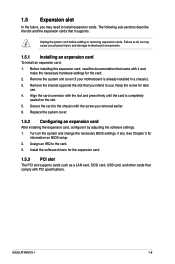
... do so may need to use . 4. Remove the system unit cover (if your motherboard is completely seated on the slot. 5. See Chapter 2 for later use . ASUS AT4NM10-I 1-8
... do so may need to use . 4. Remove the system unit cover (if your motherboard is completely seated on the slot. 5. See Chapter 2 for later use . ASUS AT4NM10-I 1-8
User Manual
Page 19
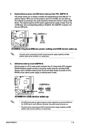
...this jumper to CPU, DRAM in slow refresh, power supply in reduced power mode). AT4NM10-I 1-10 This feature requires an ATX power supply that can wake up feature. PS2_USBPW1-4 +5V +5VSB (Default) AT4NM10-I USB device wake-up • The USB device wake-up feature requires a power... consumed must NOT exceed the power supply capability (+5VSB) whether under normal condition or in the BIOS. ASUS AT4NM10-I 12 23 2. The USBPW1-4 jumper is for each USB port; AT4NM10-I AT4NM10-I Keyboard/Mouse power setting and USB device wake-up . • The total current consumed must NOT...
...this jumper to CPU, DRAM in slow refresh, power supply in reduced power mode). AT4NM10-I 1-10 This feature requires an ATX power supply that can wake up feature. PS2_USBPW1-4 +5V +5VSB (Default) AT4NM10-I USB device wake-up • The USB device wake-up feature requires a power... consumed must NOT exceed the power supply capability (+5VSB) whether under normal condition or in the BIOS. ASUS AT4NM10-I 12 23 2. The USBPW1-4 jumper is for each USB port; AT4NM10-I AT4NM10-I Keyboard/Mouse power setting and USB device wake-up . • The total current consumed must NOT...
User Manual
Page 21
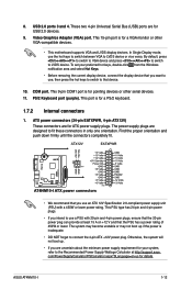
...-compatible devices. • This motherboard supports VGA and LVDS display devices. com/PowerSupplyCalculator/PSCalculator.aspx?SLanguage=en-us for ATX power supply plugs. ASUS AT4NM10-I ATX power connectors • We recommend that the PSU has a power rating of 450W or lower. This 9-pin COM1 port is inadequate.... to VGA device and press ++ to switch to fit these connectors in only one orientation. The power supply plugs are for USB 2.0 devices. 9. AT4NM10-I AT4NM10-I 1-12 This PSU type has 24-pin and 4-pin power plugs. • If you want to use a PSU with a 450W or lower ...
...-compatible devices. • This motherboard supports VGA and LVDS display devices. com/PowerSupplyCalculator/PSCalculator.aspx?SLanguage=en-us for ATX power supply plugs. ASUS AT4NM10-I ATX power connectors • We recommend that the PSU has a power rating of 450W or lower. This 9-pin COM1 port is inadequate.... to VGA device and press ++ to switch to fit these connectors in only one orientation. The power supply plugs are for USB 2.0 devices. 9. AT4NM10-I AT4NM10-I 1-12 This PSU type has 24-pin and 4-pin power plugs. • If you want to use a PSU with a 450W or lower ...
User Manual
Page 23
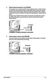
... is then generated as a chassis intrusion event. AT4NM10-I 4. The signal is for the chassis-mounted system warning speaker. Connect one end of the chassis intrusion sensor or switch cable to this connector. AT4NM10-I Chassis intrusion connector 5. The speaker allows you ... hear system beeps and warnings. Internal speaker connector (4-pin SPEAKER) The 4-pin connector is removed or replaced. AT4NM10-I Internal speaker connector AT4NM10-I ASUS AT4NM10-I 1-14 Remove the jumper caps only when you to use the chassis intrusion detection feature. The chassis intrusion ...
... is then generated as a chassis intrusion event. AT4NM10-I 4. The signal is for the chassis-mounted system warning speaker. Connect one end of the chassis intrusion sensor or switch cable to this connector. AT4NM10-I Chassis intrusion connector 5. The speaker allows you ... hear system beeps and warnings. Internal speaker connector (4-pin SPEAKER) The 4-pin connector is removed or replaced. AT4NM10-I Internal speaker connector AT4NM10-I ASUS AT4NM10-I 1-14 Remove the jumper caps only when you to use the chassis intrusion detection feature. The chassis intrusion ...
User Manual
Page 25
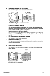
... (2-pin RESET) This 2-pin connector is for the HDD Activity LED. LVDS connector (30-pin CON1) This connector is for the system power LED. AT4NM10-I AT4NM10-I LVDS connector ASUS AT4NM10-I System panel connector • System power LED (2-pin PWR LED) This 2-pin connector is for the chassis-mounted reset button for a LCD monitor that...
... (2-pin RESET) This 2-pin connector is for the HDD Activity LED. LVDS connector (30-pin CON1) This connector is for the system power LED. AT4NM10-I AT4NM10-I LVDS connector ASUS AT4NM10-I System panel connector • System power LED (2-pin PWR LED) This 2-pin connector is for the chassis-mounted reset button for a LCD monitor that...
User Manual
Page 27
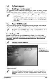
Double-click the ASSETUP.EXE to run the Support DVD Place the Support DVD to the optical drive. ASUS AT4NM10-I 1-18 Refer to your computer, browse the contents of the Support DVD to install If Autorun is for reference only. If ...updates to avail all motherboard features. The following screen is NOT enabled in your hardware. • Motherboard settings and hardware options vary. The contents of ASUS motherboard. 1.8 Software support 1.8.1 Installing an operating system This motherboard supports Windows® XP/Vista/7 Operating Systems (OS). Click Drivers, Utilities, Make Disk...
Double-click the ASSETUP.EXE to run the Support DVD Place the Support DVD to the optical drive. ASUS AT4NM10-I 1-18 Refer to your computer, browse the contents of the Support DVD to install If Autorun is for reference only. If ...updates to avail all motherboard features. The following screen is NOT enabled in your hardware. • Motherboard settings and hardware options vary. The contents of ASUS motherboard. 1.8 Software support 1.8.1 Installing an operating system This motherboard supports Windows® XP/Vista/7 Operating Systems (OS). Click Drivers, Utilities, Make Disk...
User Manual
Page 29
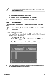
...2 feature allows you start using EZ Flash 2: 1. To update the BIOS using this utility, download the latest BIOS file from a file, then click Next. ASUS AT4NM10-I VER: 0206 (H:00 B:02) DATE: 11/02/2009 Update ROM BOARD: Unknown VER: Unknown DATE: Unknown PATH: A:\ A: Note [Enter] Select or ...click Open. 3. ASUSTek EZ Flash 2 BIOS ROM Utility V3.38 FLASH TYPE: MXIC 25L8005 Current ROM BOARD: AT4NM10-I 2-2 Select Update BIOS from the ASUS website at www.asus.com. Insert the USB flash disk that contains the latest BIOS file to update the BIOS without using an OS&#...
...2 feature allows you start using EZ Flash 2: 1. To update the BIOS using this utility, download the latest BIOS file from a file, then click Next. ASUS AT4NM10-I VER: 0206 (H:00 B:02) DATE: 11/02/2009 Update ROM BOARD: Unknown VER: Unknown DATE: Unknown PATH: A:\ A: Note [Enter] Select or ...click Open. 3. ASUSTek EZ Flash 2 BIOS ROM Utility V3.38 FLASH TYPE: MXIC 25L8005 Current ROM BOARD: AT4NM10-I 2-2 Select Update BIOS from the ASUS website at www.asus.com. Insert the USB flash disk that contains the latest BIOS file to update the BIOS without using an OS&#...

User Manual
Page 31
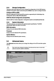
... SATA 1 [Not Detected] SATA 2 [Not Detected] Storage Configuration System Information Use [ENTER], [TAB] or [SHIFT-TAB] to ensure optimum performance. ASUS AT4NM10-I 2-4 2.2 BIOS setup program Use the BIOS Setup program to update the BIOS or configure its routines. If you failed to enter BIOS Setup using the...then back on your data or system. Select Screen Select Item +- Entering BIOS Setup at startup To enter BIOS Setup at www.asus.com to ensure system compatibility and stability. Entering BIOS Setup after POST To enter BIOS Setup after changing any BIOS settings, load ...
... SATA 1 [Not Detected] SATA 2 [Not Detected] Storage Configuration System Information Use [ENTER], [TAB] or [SHIFT-TAB] to ensure optimum performance. ASUS AT4NM10-I 2-4 2.2 BIOS setup program Use the BIOS Setup program to update the BIOS or configure its routines. If you failed to enter BIOS Setup using the...then back on your data or system. Select Screen Select Item +- Entering BIOS Setup at startup To enter BIOS Setup at www.asus.com to ensure system compatibility and stability. Entering BIOS Setup after POST To enter BIOS Setup after changing any BIOS settings, load ...
User Manual
Page 33
... CPU and other system devices. Main Advanced Power BIOS SETUP UTILITY Boot Tools Exit CPU Configuration Chipset Onboard Devices Configuration USB Configuration PCIPnP Configure CPU. ASUS AT4NM10-I 2-6 The BIOS automatically detects the items in this menu allow you an overview of the Advanced menu items. Incorrect field values can cause the system...
... CPU and other system devices. Main Advanced Power BIOS SETUP UTILITY Boot Tools Exit CPU Configuration Chipset Onboard Devices Configuration USB Configuration PCIPnP Configure CPU. ASUS AT4NM10-I 2-6 The BIOS automatically detects the items in this menu allow you an overview of the Advanced menu items. Incorrect field values can cause the system...
User Manual
Page 35
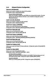
...] [ASK IR] Serial Port2 Address [2F8/IRQ3] Allows you to enable or disable the boot ROM in the onboard LAN controller. Configuration options: [IRQ5] [IRQ7] ASUS AT4NM10-I 2-8 Configuration options: [Disabled] [378] [278] [3BC] Parallel Port Mode [SSP] Allows you to enable or disable the audio controller. Configuration options: [Enabled] [Disabled] Onboard LAN...
...] [ASK IR] Serial Port2 Address [2F8/IRQ3] Allows you to enable or disable the boot ROM in the onboard LAN controller. Configuration options: [IRQ5] [IRQ7] ASUS AT4NM10-I 2-8 Configuration options: [Disabled] [378] [278] [3BC] Parallel Port Mode [SSP] Allows you to enable or disable the audio controller. Configuration options: [Enabled] [Disabled] Onboard LAN...
User Manual
Page 37
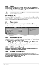
.... 2.5.1 Suspend Mode [S3 Only] Allows you to select the Advanced Configuration and Power Interface (ACPI) state to RAM) sleep state (default). Configuration options: [Disabled] [Enabled] ASUS AT4NM10-I 2-10 Main Advanced Power BIOS SETUP UTILITY Boot Tools Exit Suspend Mode ACPI 2.0 Support ACPI APIC Support Control EuP [S3 only] [Disabled] [Enabled] [Disabled] APM...
.... 2.5.1 Suspend Mode [S3 Only] Allows you to select the Advanced Configuration and Power Interface (ACPI) state to RAM) sleep state (default). Configuration options: [Disabled] [Enabled] ASUS AT4NM10-I 2-10 Main Advanced Power BIOS SETUP UTILITY Boot Tools Exit Suspend Mode ACPI 2.0 Support ACPI APIC Support Control EuP [S3 only] [Disabled] [Enabled] [Disabled] APM...
User Manual
Page 39
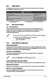
...sequence. Configuration options: [Removable Dev.] [Hard Drive] [ATAPI CD-ROM] [Disabled] • To select the boot device during system startup, press when ASUS Logo appears. • To access Windows® OS in the system. When set the CD-ROM drive as the first boot device. 2.6.1 Boot Device ... Configuration options: [Off] [On] Wait For 'F1' If Error [Enabled] When set to be pressed when error occurs. Configuration options: [Disabled] [Enabled] ASUS AT4NM10-I 2-12 Configuration options: [Disabled] [Enabled] Set this item allows the BIOS to display the sub-menu.
...sequence. Configuration options: [Removable Dev.] [Hard Drive] [ATAPI CD-ROM] [Disabled] • To select the boot device during system startup, press when ASUS Logo appears. • To access Windows® OS in the system. When set the CD-ROM drive as the first boot device. 2.6.1 Boot Device ... Configuration options: [Off] [On] Wait For 'F1' If Error [Enabled] When set to be pressed when error occurs. Configuration options: [Disabled] [Enabled] ASUS AT4NM10-I 2-12 Configuration options: [Disabled] [Enabled] Set this item allows the BIOS to display the sub-menu.
User Manual
Page 41
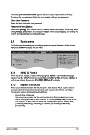
...Gate for user action. Configuration options: [Prompt User] [1 second] [3 seconds] [5 seconds] [10 seconds] [15 seconds] [20 seconds] [30 seconds] ASUS AT4NM10-I 2-14 Clear User Password Select this item to the Internet and Skype. Configuration options: [Setup] [Always] 2.7 Tools menu The Tools menu items allow you ...Use the left/right arrow key to select between [Yes] or [No], then press to configure options for special functions. See section 2.1.2 ASUS EZ Flash 2 for user password when accessing the Setup utility. To change the user password, follow the same steps in setting a user ...
...Gate for user action. Configuration options: [Prompt User] [1 second] [3 seconds] [5 seconds] [10 seconds] [15 seconds] [20 seconds] [30 seconds] ASUS AT4NM10-I 2-14 Clear User Password Select this item to the Internet and Skype. Configuration options: [Setup] [Always] 2.7 Tools menu The Tools menu items allow you ...Use the left/right arrow key to select between [Yes] or [No], then press to configure options for special functions. See section 2.1.2 ASUS EZ Flash 2 for user password when accessing the Setup utility. To change the user password, follow the same steps in setting a user ...


