AP1710-I5 English Manual
Page 2
... OR INACCURACIES THAT MAY APPEAR IN THIS MANUAL, INCLUDING THE PRODUCTS AND SOFTWARE DESCRIBED IN IT. Product Name: AP1710-I5 Manual Revision: First Edition E1304 Release Date: June 2003 ii ASUS AP1710-I5 IN NO EVENT SHALL ASUS, ITS DIRECTORS, OFFICERS, EMPLOYEES OR AGENTS BE LIABLE FOR ANY INDIRECT, SPECIAL, INCIDENTAL, OR CONSEQUENTIAL DAMAGES (INCLUDING DAMAGES...
... OR INACCURACIES THAT MAY APPEAR IN THIS MANUAL, INCLUDING THE PRODUCTS AND SOFTWARE DESCRIBED IN IT. Product Name: AP1710-I5 Manual Revision: First Edition E1304 Release Date: June 2003 ii ASUS AP1710-I5 IN NO EVENT SHALL ASUS, ITS DIRECTORS, OFFICERS, EMPLOYEES OR AGENTS BE LIABLE FOR ANY INDIRECT, SPECIAL, INCIDENTAL, OR CONSEQUENTIAL DAMAGES (INCLUDING DAMAGES...
AP1710-I5 English Manual
Page 4
... with the limits for help. Canadian Department of Communications This digital apparatus does not exceed the Class B limits for connection of the FCC Rules. iv ASUS AP1710-I5 FCC/CDC Statements Federal Communications Commission This device complies with Canadian ICES-003. The use of the following two conditions: • This device may not...
... with the limits for help. Canadian Department of Communications This digital apparatus does not exceed the Class B limits for connection of the FCC Rules. iv ASUS AP1710-I5 FCC/CDC Statements Federal Communications Commission This device complies with Canadian ICES-003. The use of the following two conditions: • This device may not...
AP1710-I5 English Manual
Page 6
2.7 Screwless Expansion Card Slot 2-23 2.8 Long Card Support Guide 2-24 2.9 RAID Card 2-25 2.10 Hard Drive Blower 2-26 2.11 Chassis Fan 2-27 2.12 Connecting Cables 2-28 2.13 SCSI Backplane 2-29 Appendix A: Optional chassis roller-wheel Chassis Roller-wheel Installation A-2 Appendix B: Power Modules Redundant Power Modules A-4 Appendix C: Troubleshooting Troubleshooting A-9 vi ASUS AP1710-I5
2.7 Screwless Expansion Card Slot 2-23 2.8 Long Card Support Guide 2-24 2.9 RAID Card 2-25 2.10 Hard Drive Blower 2-26 2.11 Chassis Fan 2-27 2.12 Connecting Cables 2-28 2.13 SCSI Backplane 2-29 Appendix A: Optional chassis roller-wheel Chassis Roller-wheel Installation A-2 Appendix B: Power Modules Redundant Power Modules A-4 Appendix C: Troubleshooting Troubleshooting A-9 vi ASUS AP1710-I5
AP1710-I5 English Manual
Page 8
CD-ROM Drive Safety Warning CLASS 1 LASER PRODUCT • Electrical hazard, do not remove chassis cover. • This equipment is incorrectly replaced. Lithium-Ion Battery Warning CAUTION: Danger of used batteries according to be serviced by the manufacturer. viii ASUS AP1710-I5 Replaced only with the same or equivalent type recommended by a trained personnel only. Dispose of explosion if battery is to the manufacturer's instructions.
CD-ROM Drive Safety Warning CLASS 1 LASER PRODUCT • Electrical hazard, do not remove chassis cover. • This equipment is incorrectly replaced. Lithium-Ion Battery Warning CAUTION: Danger of used batteries according to be serviced by the manufacturer. viii ASUS AP1710-I5 Replaced only with the same or equivalent type recommended by a trained personnel only. Dispose of explosion if battery is to the manufacturer's instructions.
AP1710-I5 English Manual
Page 10
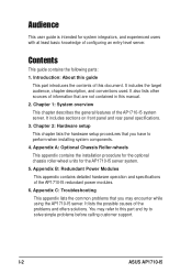
...1: System overview This chapter describes the general features of the AP1710-I5 redundant power modules. 6. Appendix B: Redundant Power Modules This appendix contains detailed hardware operation and specifications of the AP1710-I5 system server. Appendix C: Troubleshooting This appendix lists the common problems... user guide is intended for the AP1710-I5 server system. 5. It includes the target audience, chapter description, and conventions used. It also lists other sources of configuring an entry-level server. You may encounter while using the AP1710-I5 server. I-2 ASUS AP1710-I5
...1: System overview This chapter describes the general features of the AP1710-I5 redundant power modules. 6. Appendix B: Redundant Power Modules This appendix contains detailed hardware operation and specifications of the AP1710-I5 system server. Appendix C: Troubleshooting This appendix lists the common problems... user guide is intended for the AP1710-I5 server system. 5. It includes the target audience, chapter description, and conventions used. It also lists other sources of configuring an entry-level server. You may encounter while using the AP1710-I5 server. I-2 ASUS AP1710-I5
AP1710-I5 English Manual
Page 12
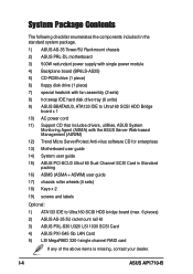
... is missing, contact your dealer. System Package Contents The following checklist enumerates the components included in the standard system package. 1) ASUS AS-35 Tower/5U Rackmount chassis 2) ASUS PRL-DL motherboard 3) 500W redundant power supply with single power module 4) Backplane board (BP6LS-AS35) 5) CD-ROM drive ... wheels (4 sets) 18) Keys x 2 19) screws and labels Optional: 1) ATA133 IDE to Ultra160 SCSI HDD bridge board (max. 6 pieces) 2) ASUS AS-35 5U rackmount rail kit 3) ASUS PXL-S30 U320 LSI 1030 SCSI Card 4) ASUS PXI-G45 Gb LAN Card 5) LSI MegaRAID 320-I -4 ASUS AP1710-I5
... is missing, contact your dealer. System Package Contents The following checklist enumerates the components included in the standard system package. 1) ASUS AS-35 Tower/5U Rackmount chassis 2) ASUS PRL-DL motherboard 3) 500W redundant power supply with single power module 4) Backplane board (BP6LS-AS35) 5) CD-ROM drive ... wheels (4 sets) 18) Keys x 2 19) screws and labels Optional: 1) ATA133 IDE to Ultra160 SCSI HDD bridge board (max. 6 pieces) 2) ASUS AS-35 5U rackmount rail kit 3) ASUS PXL-S30 U320 LSI 1030 SCSI Card 4) ASUS PXI-G45 Gb LAN Card 5) LSI MegaRAID 320-I -4 ASUS AP1710-I5
AP1710-I5 English Manual
Page 14
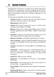
...3.06 GHz frequency with single power module. • Hardware Monitors: Voltage, temperature, Automatic System Restart (ASR), fan speed. 1-2 ASUS AP1710-I5 The following are highlights of the server's many features: • Chassis: Pedestal or rackmount 5U with removable front door bezel and ...Ethernet controller • Drive Controller: LSI 53C1010R/32-bit/33MHz Dual Ultra-160 channels. 1.1 System Features The ASUS AP1710-I5 server is a stylish server system featuring the ASUS PRL-DL motherboard. The server supports the Intel® Xeon™ processor in a 604-pin socket, and...
...3.06 GHz frequency with single power module. • Hardware Monitors: Voltage, temperature, Automatic System Restart (ASR), fan speed. 1-2 ASUS AP1710-I5 The following are highlights of the server's many features: • Chassis: Pedestal or rackmount 5U with removable front door bezel and ...Ethernet controller • Drive Controller: LSI 53C1010R/32-bit/33MHz Dual Ultra-160 channels. 1.1 System Features The ASUS AP1710-I5 server is a stylish server system featuring the ASUS PRL-DL motherboard. The server supports the Intel® Xeon™ processor in a 604-pin socket, and...
AP1710-I5 English Manual
Page 16
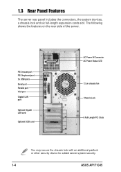
... Chassis Lock 6 Full-Length PCI Slots You may secure the chassis lock with an additional padlock or other security device for added server system security. 1-4 ASUS AP1710-I5 The following shows the features on the rear side of the server. 1.3 Rear Panel Features The server rear panel includes the connectors, the system devices...
... Chassis Lock 6 Full-Length PCI Slots You may secure the chassis lock with an additional padlock or other security device for added server system security. 1-4 ASUS AP1710-I5 The following shows the features on the rear side of the server. 1.3 Rear Panel Features The server rear panel includes the connectors, the system devices...
AP1710-I5 English Manual
Page 18
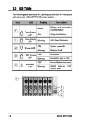
1.5 LED Table The following table describes the LED display found on the front panel and rear panel of the AP1710-I5 server system. Icon 1 1 2 3 4 LED Display Description Green Drive Status LED Red Bridge board connected to SCSI backplane Bridge board failure Drive Activity LED Blinking HDD Read/Write data ON Power LED Blinking HDD Access OFF LED Blinking Message LED OFF Blinking System power ON Suspend Mode No activity Read/Write data in HDD Normal/No incoming event ASMS indicate HW monitor event 1 2 3 4 1-6 ASUS AP1710-I5
1.5 LED Table The following table describes the LED display found on the front panel and rear panel of the AP1710-I5 server system. Icon 1 1 2 3 4 LED Display Description Green Drive Status LED Red Bridge board connected to SCSI backplane Bridge board failure Drive Activity LED Blinking HDD Read/Write data ON Power LED Blinking HDD Access OFF LED Blinking Message LED OFF Blinking System power ON Suspend Mode No activity Read/Write data in HDD Normal/No incoming event ASMS indicate HW monitor event 1 2 3 4 1-6 ASUS AP1710-I5
AP1710-I5 English Manual
Page 20
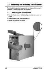
The side chassis cover is designed for about half an inch. 3. Release the cover from the chassis. 2-2 ASUS AP1710-I5 Loosen the screws. 2. Slide the chassis cover for easy assembly and disassembly, making the installation of internal components very convenient. 2.1.1 Removing the chassis cover 1. 2.1 Removing and installing chassis cover The chassis is held by two large thumb screws.
The side chassis cover is designed for about half an inch. 3. Release the cover from the chassis. 2-2 ASUS AP1710-I5 Loosen the screws. 2. Slide the chassis cover for easy assembly and disassembly, making the installation of internal components very convenient. 2.1.1 Removing the chassis cover 1. 2.1 Removing and installing chassis cover The chassis is held by two large thumb screws.
AP1710-I5 English Manual
Page 22
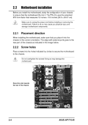
... When installing the motherboard, make sure that measures 12 inches x 10.5 inches (30.5 x 26.67 cm). Place this side towards the rear of the chassis 2-4 ASUS AP1710-I5 The PRL-DL uses the extended ATX form factor that you place it into the chassis in the image below. 2.2.2 Screw holes Place screws into...
... When installing the motherboard, make sure that measures 12 inches x 10.5 inches (30.5 x 26.67 cm). Place this side towards the rear of the chassis 2-4 ASUS AP1710-I5 The PRL-DL uses the extended ATX form factor that you place it into the chassis in the image below. 2.2.2 Screw holes Place screws into...
AP1710-I5 English Manual
Page 24
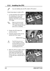
... sockets on the socket while you are installing only one correct orientation. Unlock the socket by pressing the lever sideways, then lift it is locked. 2-6 ASUS AP1710-I5 Follow these steps to at least 115° angle, otherwise the CPU does not fit in place, press it fits in CPU socket 1. Marked Corner...
... sockets on the socket while you are installing only one correct orientation. Unlock the socket by pressing the lever sideways, then lift it is locked. 2-6 ASUS AP1710-I5 Follow these steps to at least 115° angle, otherwise the CPU does not fit in place, press it fits in CPU socket 1. Marked Corner...
AP1710-I5 English Manual
Page 26
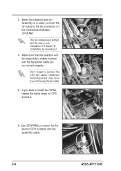
... connector on the motherboard labeled CPUFAN1. Don't forget to install two CPUs, repeat the same steps for the second CPU heatsink and fan assembly cable. 2-8 ASUS AP1710-I5 If it doesn't fit completely, try reversing it fits only in place, connect the fan cable to plug the fan cable. 5. Use CPUFAN2 connector for...
... connector on the motherboard labeled CPUFAN1. Don't forget to install two CPUs, repeat the same steps for the second CPU heatsink and fan assembly cable. 2-8 ASUS AP1710-I5 If it doesn't fit completely, try reversing it fits only in place, connect the fan cable to plug the fan cable. 5. Use CPUFAN2 connector for...
AP1710-I5 English Manual
Page 28
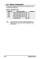
2.5.2 Memory Configurations The motherboard supports system memory of up to use only the specified DIMM types for stable system operation. 2-10 ASUS AP1710-I5 Memory configuration table DIMM Socket 184-pin ECC DDR DIMM Total Memory DDRA1 SDRAM 128MB, 256MB, 512MB, 1GB, 2GB (x1) = DDRA2 DDRB1 DDRB2 SDRAM 128MB, ...
2.5.2 Memory Configurations The motherboard supports system memory of up to use only the specified DIMM types for stable system operation. 2-10 ASUS AP1710-I5 Memory configuration table DIMM Socket 184-pin ECC DDR DIMM Total Memory DDRA1 SDRAM 128MB, 256MB, 512MB, 1GB, 2GB (x1) = DDRA2 DDRB1 DDRB2 SDRAM 128MB, ...
AP1710-I5 English Manual
Page 30
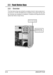
An IDE CD-ROM drive is installed on the uppermost bay and two free bays are cinched by screwless locks for installation of additional storage devices like optical disc drives or tape drives. Front door bezel Screwless fixed device bay locks 2-12 ASUS AP1710-I5 2.5 Fixed Device Bays 2.5.1 Overview The fixed device bay are available for device placement convenience.
An IDE CD-ROM drive is installed on the uppermost bay and two free bays are cinched by screwless locks for installation of additional storage devices like optical disc drives or tape drives. Front door bezel Screwless fixed device bay locks 2-12 ASUS AP1710-I5 2.5 Fixed Device Bays 2.5.1 Overview The fixed device bay are available for device placement convenience.
AP1710-I5 English Manual
Page 32
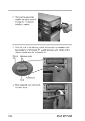
Remove the appropriate metallic bay panel cover of the drive bay, unlock and remove the screwless drive bay lock by turning the knob 45º counter-clockwise until it aside. 2-14 ASUS AP1710-I5 Unlock Reference points icon Locked icon Knob 4. From the side of the bay slot you want to install your device. 3. out the lock and set it clicks on the reference point near the "unlocked icon". When released, pull- 2.
Remove the appropriate metallic bay panel cover of the drive bay, unlock and remove the screwless drive bay lock by turning the knob 45º counter-clockwise until it aside. 2-14 ASUS AP1710-I5 Unlock Reference points icon Locked icon Knob 4. From the side of the bay slot you want to install your device. 3. out the lock and set it clicks on the reference point near the "unlocked icon". When released, pull- 2.
AP1710-I5 English Manual
Page 34
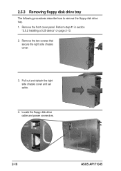
Locate the floppy disk drive cable and power connectors. 2-16 ASUS AP1710-I5 Remove the two screws that secure the right side chassis cover. 3. Pull out and detach the right side chassis cover and set aside. 4. 2.5.3 Removing floppy disk drive tray The following procedures describe how to remove the floppy disk drive tray. 1. Perform step #1 in section "2.5.2 Installing a 5.25 device" on page 2-13. 2. Remove the front cover panel.
Locate the floppy disk drive cable and power connectors. 2-16 ASUS AP1710-I5 Remove the two screws that secure the right side chassis cover. 3. Pull out and detach the right side chassis cover and set aside. 4. 2.5.3 Removing floppy disk drive tray The following procedures describe how to remove the floppy disk drive tray. 1. Perform step #1 in section "2.5.2 Installing a 5.25 device" on page 2-13. 2. Remove the front cover panel.
AP1710-I5 English Manual
Page 36
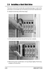
2.6 Installing a Hard Disk Drive The server comes with six externally accessible drive bays. When the tray lever is a removable tray for mounting an SCA SCSI hard disk drive. Lift the spring lock upwards, then pull the tray lever outwards. 2. To release the drive bay, follow these steps. 1. In each of the drive bays is pulled down, the tray will eject slightly. Pull the tray outwards on the tray lever. 2-18 ASUS AP1710-I5
2.6 Installing a Hard Disk Drive The server comes with six externally accessible drive bays. When the tray lever is a removable tray for mounting an SCA SCSI hard disk drive. Lift the spring lock upwards, then pull the tray lever outwards. 2. To release the drive bay, follow these steps. 1. In each of the drive bays is pulled down, the tray will eject slightly. Pull the tray outwards on the tray lever. 2-18 ASUS AP1710-I5
AP1710-I5 English Manual
Page 38
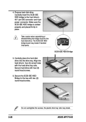
... 2-20 Do not overtighten the screws, the plastic drive tray rails may break if handled improperly. 5. Secure hard drive with the hard drive tray rails. ASUS AP1710-I5 Carefully insert the SCSI-IDE HDD bridge to the hard disk drive. Prepare hard disk drive. 4. Make sure the SCSI-IDE HDD bridge is slotted...
... 2-20 Do not overtighten the screws, the plastic drive tray rails may break if handled improperly. 5. Secure hard drive with the hard drive tray rails. ASUS AP1710-I5 Carefully insert the SCSI-IDE HDD bridge to the hard disk drive. Prepare hard disk drive. 4. Make sure the SCSI-IDE HDD bridge is slotted...
AP1710-I5 English Manual
Page 40
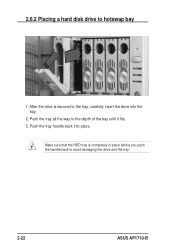
Push the tray handle back into the bay. 2. After the drive is completely in place before you push the handle back to the depth of the bay until it fits. 3. Push the tray all the way to avoid damaging the drive and the tray. 2-22 ASUS AP1710-I5 Make sure that the HDD tray is secured to hotswap bay 1. 2.6.2 Placing a hard disk drive to the tray, carefully insert the drive into place.
Push the tray handle back into the bay. 2. After the drive is completely in place before you push the handle back to the depth of the bay until it fits. 3. Push the tray all the way to avoid damaging the drive and the tray. 2-22 ASUS AP1710-I5 Make sure that the HDD tray is secured to hotswap bay 1. 2.6.2 Placing a hard disk drive to the tray, carefully insert the drive into place.


